www.ijiset.com
99
Shear Strength of High Strength Fibre Reinforced
Concrete Beam
Alphy bawa P 1
P
, Dr Sunilaa George P 2
P
1
P
P.G. Student, Department of Civil Engineering, EASA College of Engineering and Technology Navakkarai, Coimbatore, India
P
2
P
Professor and Head of Civil Engineering Department, EASA College of Engineering and Technology Navakkarai, Coimbatore, India
Abstract
This study deals with the experimental investigation to find the effect of steel fibers on the behavior and strength of reinforced high strength concrete beams under shear with or without fibre . The fiber content used in study ranged from 0.25,0.50,0.75 and 1.0%, and the aspect ratio of the fibers were taken as 40. Fibers proved to be more effective in HSC by increasing the ductility and ultimate load carrying capacity.With steel fibers improvement of first crack load and ultimate load over that of plain concrete was noted. The experimentally obtained shear stresses were compared with available equations in the literatures. The equations as per IS 456:2000 for calculating shear stress was modified by introducing a fibre factor
Keyword: steel fiber, super plasticizer, HSC :High strength concrete
1.Indroduction
Concrete is an engineering material used for constructional application. There are different types of concrete, like normal strength concrete, high strength concrete and ultra high strength etc. The shear failure in concrete is known to be brittle in nature and catastrophic. In usual structural design, shear is accounted by providing shear reinforcement such as stirrups in beams and dowel in slab. When dealing with high strength concrete, it is inherently more brittle than normal strength concrete. The low toughness characteristics of high strength concrete can result in sudden and catastrophic shear failure. This requires special consideration in critical section, where due to construction limitation; steel may or may not be utilized as shear reinforcement. For improving the shear performance of structural concrete the vertical stirrups can be replaced by introducing steel fibers with various fibre content and aspect ratioP
4
Keeping in pace with progress made in the field of science and technology, Civil Engineering construction has made speedy advances and has undergone a number of changes over the year. Engineering materials are available from natural sources whose properties cannot be easily altered.
Also they can be manufactured known as artificial engineering materials, which possess the desired properties. Many investigations were carried out on the study of the behaviour of steel fibre reinforced concrete beam subjected to predominant shearP
1
P
. The ultimate strength of fibrous beams under shear was much higher than that of the concrete beam depending on the energy absorbed in deboning and stretching the fibers, which is directly proportional to the fibre volume content and aspect ratio. Both the shear crack stress and the ultimate shear strength were found to be increasing with the shear reinforcement ratioP
5
P
1.1
Steel Fibre Reinforced High Strength
Concrete
Fibres are randomly distributed throughout the concrete volume at relatively small spacing and thus provide resistance to stress in all direction. This may be beneficial in structural design to resist shear force due to earthquake and wind loading. The increased resistance of the concrete cover to spilling and cracking help to protect steel from corrosion in adverse environment and hence improve the structural durability. Steel fibres can be used for reinforcing concrete structures like beams, columns, joint connections etc. The parameters varied in the studies are volume fraction of fibre, shear span to depth ratio and the concrete compressive strengthP
2
One of the promising structural applications of fibre reinforced concrete is the use of fibres as shear reinforcement. Addition of fibres generally improves the shear strength, beam stiffness and ductility of concreteP
6
P
100
associated with reinforcement installation. Also,casting concrete in beams with closely-spaced stirrups could be difficult and might lead to voids and associated poor bond between concrete and reinforcing bars. An alternative solution to stirrup reinforcement is the use of randomly oriented steel fibres, which have been shown to increase shear resistance. As the size of beam increases shear strength show a decreasing valueP
6
P
. For some studies, in addition to concrete compressive strength influence of other variables such as shear span to depth ratio, longitudinal steel ratio and size effect is also consideredP
8
P
.
Increasing the amount of fiber was found to reduce the crack width and increasing the shear strengthP
7
P
. Fibres concrete can also be easily placed in thin or irregularly shaped sections such as architectural panels, where it may be very difficult to place stirrups. The different advantages of fibres in concrete are, it enhances the
Durability of concrete Ductility of concrete
Shear strength, tensile strength and flexural strength of concrete
Energy absorption and impact resistanceP
9
2. Materials and their Properties
The materials selected for HSC mix were OPC (Ordinary Portland cement) 53 grade, fine aggregate (river sand <4.75mm), fly ash, super plasticizer and water. Each material was tested as per the specification in the relevant IS codes.
2.1 Cement
Ordinary Portland cement, Dalmia 53 grade conforming to IS 1269:1999[24] used in this experiment. The different laboratory tests were conducted on cement as per IS 4031:1967(reaffirmed 1995) [25].The test results on cement are tabulated in table 1.
Table 1 Test Result On Cement
Standards consistency of cement (%) 31 Initial setting time of cement(minutes) 80 Final setting time of cement (minute) 485 3 day compressive strength of
cement(N/mmP
2
P
)
27.6
7 day compressive strength of cement(N/mmP
2
P
)
39.876
28 day compressive strength of cement(N/mmP
2
P
)
54.465
2.2 Fine Aggregate
Locally available river sand passing through 4.75 mm sieve was used. The various physical properties of fine aggregate were determined as per IS: 2386(part III)1963 (reaffirmed2002) [26] and results are given in table 2. shows the gradation curve for fine aggregate used. The result shows that fine aggregate falls in zone II.
Table 2 Properties of Fine aggregate
Bulk density of fine aggregate
1.637g/cc
Void ratio of fine aggregate 0.568 Porosity of fine aggregate 36%
Specific gravity of fine aggregate
2.69
Fineness modulus of fine aggregate
2.95
2.3 Coarse Aggregate
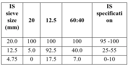
Coarse aggregate are used are of two sizes 20mm maximum size and 12.5mm maximum size. The aggregate were combined in the ratio 3:2 to obtain 20mm graded aggregate. The result of sieve analysis for 20mm and 12.5mm combined aggregate were given Table 3 Properties of the coarse aggregate are also given in Table 4. The aggregates gradation curve for coarse aggregate used.
Table 3 Combined sieve analysis of coarse aggregate
IS sieve
size (mm)
20 12.5 60:40
IS specificati
on
20.0 100 100 100 95 -100
12.5 5.0 92.5 40.0 25-55
4.75 0 17.5 7.0 0-10
Table 4 Properties of coarse aggregate
Bulk density of coarse aggregate 1.623g/cc Void ratio of coarse aggregate 0.97
Porosity of coarse aggregate 49% Specific gravity of coarse
aggregate
www.ijiset.com
101
2.4 Steel Fibre
The steel fibre having a diameter of 0.5mm and an aspect ratio 40 were used in the study. The length of the fibre used was 20mm.Properties of steel fibres are given in table 5 shows the steel fibres before cutting
Table 5 Properties of Steel Fibre
Length(mm) and Diameter(mm) 20 and 0.5 Aspect ratio(l/d) 40 Ultimate Stress(N/mmP
2
P
) 412
2.5 Mineral Admixture
Class C fly ash supplied by Hindustan News print Factory, at Kottayam was used and its specific gravity is given as 2.64 by the supplier
2.6 Chemical Admixture
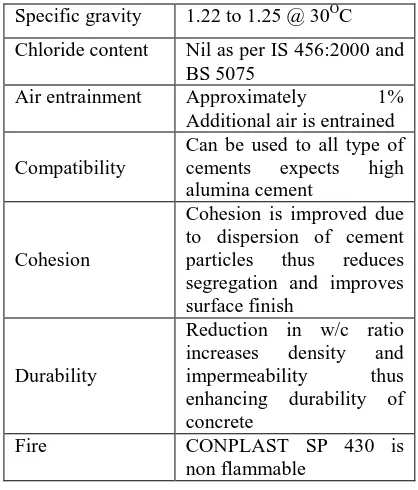
The super plasticizer used was CONPLAST SP 430 a product of FOSROC Chemical India Pvt. Ltd, Bangalore. The properties of the super plasticizer supplied by the manufacture are given in table 6
Table 6 Properties of CONPLAST SP 430
Specific gravity 1.22 to 1.25 @ 30P
O
P
C
Chloride content Nil as per IS 456:2000 and BS 5075
Air entrainment Approximately 1% Additional air is entrained
Compatibility
Can be used to all type of cements expects high alumina cement
Cohesion
Cohesion is improved due to dispersion of cement particles thus reduces segregation and improves surface finish
Durability
Reduction in w/c ratio increases density and impermeability thus enhancing durability of concrete
Fire CONPLAST SP 430 is
non flammable
2.7 Water
Potable clean drinking water available in the college water supply system was used for casting as well as for curing of the test specimens.
2.8 Reinforcement
Mild steel bars of 12, 8 and 6mm diameter were used as reinforcement for the beam specimen.12mm diameter bars were used as bottom bar and 8mm diameter bar as top reinforcement and 6mm diameter bar as stirrup for holding top and bottom bars. Properties of the bars used are shown in table 7
Table 7 Properties of Reinforcement
Bar diameter
in(mm)
Yield stress in (N/mmP
2
P
)
Breaking stress in (N/mmP
2
P
)
% Elongation
12 468.39 572.48 22.5 8 448.13 538.92 29.82 6 423.50 536.32 36.66
3.Experimental Work And Tests
3.1 Mix Design
IS Code does not specify the design procedure for concrete with strength greater than 55MPa.The first step in the design is the selection of slump and the required concrete strength. Based on the strength requirements, the recommended maximum sizes of coarse aggregate are chosen. Mixing water and air content are estimated according to slump and maximum size of aggregates. Then the water/cement ratio found from various trials. The content aggregate and coarse aggregate can be found from the total volume of the concrete. Details calculation of mix design are given in appendix A
UQuantities of material requirement per mUP
3
PU
for M60 mix
Cement = 502.43 kg/mP
3
Fly ash = 125.606 kg/mP
3
Fine aggregate = 491.89 kg/mP
3
Coarse aggregate = 1090.24 kg/mP
3
Water = 201 kg/mP
3
Super plasticizer = 0.5% to 0.8%
3.2 Tests on Fresh HSC
3.2.1 Compaction Factor Test
102
Table 8 Compaction Factor for Different Trial Mixes
Mix w/c
ratio
Superplasticiser (% of cement)
Compaction factor
M1 0.32 0.60 0.9
M2 0.32 0.60 0.86
M3 0.32 0.60 0.8
3.2.2 Tests On Hardened HSC
3.2.2.1 Cube Compressive Strength
The compressive strength is one of the most important properties of hardened concrete. Compressive strength at 7 and 28 days was tested on cubes of size 150 x 150 x 150mm. six cube samples for each trial mixes were cast for testing. The specimens were cast tested as per the specifications in IS 516(reaffirmed in 2000) .
3.2.2.2 Cylinder Compressive Strength
Compressive strength test on three cylinder specimens of size 150mm x300mm were carried out after 28 days water curing. The specimens were cast and tested as per the specifications in IS 516(reaffirmed in 2000) .
3.2.2.3 Modulus of Elasticity
To determine modulus of elasticity three cylinder specimens of size 150mm x 300mm were cast. The specimens were cast and tested as per the specifications in IS 516(reaffirmed in 2000) .
3.2.2.4 Split Tensile Strength
To determine split tensile strength three cylinder specimens of size 150mm x 300mm were cast. The specimens were cast and tested as per the specifications in IS 516(reaffirmed in 2000) .
3.2.2.5 Flexural Strength
To determine flexural strength three beam specimens of size 100mm x 100mm x500mm were cast. The specimens were cast and tested as per the specifications in IS 516(reaffirmed in 2000) .
Table 9 Properties of Hardened HSC
Property (N/mmP
2
P
) Cube
compressive strength
7 day 64
28 day 79.25
Cylinder compressive strength
63.90
Modulus of elasticity 6.96× 10⁴ Split tensile strength 3.11 Flexural strength 4.37
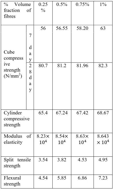
3.3 Fresh And Hardened Properties Of HSFRC
Fibre reinforced high strength concrete was made by adding fibres to the prepared mix. Different mixes were made by varying the volume of fibres from 0.25% to1%. When fibers were added to concrete,workability got reduced. Inorder to maintain a uniform workability of 0.9 compaction factor, dosage of SP was increased as shown in table 10. The fresh and hardened properties of those fibre reinforced high strength concrete are given in table 10 and 11.
Table 10 Fresh Properties of HSFRC
Mix w/c
rati o
Superplasticiser (% of cement)
Compac tion factor HSFRC 1 0.32 0.63 0.9 HSFRC 2 0.32 0.7 0.9 HSFRC 3 0.32 0.76 0.9 HSFRC 4 0.32 0.8 0.9
Table 11 Hardened Properties of HSFRC
% Volume fraction of fibres
0.25 %
0.5% 0.75% 1%
Cube compress ive strength (N/mmP
2
P
)
56 56.55 58.20 63 7
d a y 2 8 d a y
80.7 81.2 81.96 82.3
Cylinder compressive strength
65.4 67.24 67.42 68.67
Modulus of elasticity
8.23×
104 8.54104× 8.63104× × 108.6434
Split tensile strength
3.54 3.82 4.53 4.95
Flexural strength
www.ijiset.com
103
4 . Test Results And Discussions
4.1 First Crack Load And Ultimate Load
The result obtained are tabulated in table 12. The values shown in the table 12 are the average of results obtained from the tests on three identical beams.
Table 12. First Crack Load and Ultimate Load
Designation of beam specimen
First crack load (KN)
Ultimate load (KN)
Deflection at ultimate load (mm)
𝐶𝐵0% 31 41 4.06
𝐹𝐵0.25% 38 52 4.92
𝐹𝐵0.5% 40 59 5.69
𝐹𝐵0.75% 52 78 6.02
𝐹𝐵1% 67 102 6.54
Referring to table 4.1 following points may be noted. As the fibre content increases, the first crack load and ultimate load increases significantly. The first cracking load in the case of fibre reinforced high strength concrete beam with different volume fraction of fibres were found to be more when compared to beams without steel fibre. The maximum first crack load was noticed in the case of specimens with 1% fibres. Similarly ultimate load also increased due to the addition of fibres and at 1% fibre the increase was about 60%. The comparison of first crack load for various volume fractions of fibres were shown in figure 1.The comparison of ultimate load for volume fractions fibres were shown in figure 2
Fig 1 Comparison of First Crack Load Due to Addition of Fibre
Fig 2 Comparison of Ultimate load due to addition of fibre
4.2 Energy Absorption Capacity
An attempt was made to obtain the energy absorption capacity of specimens. In general the term energy absorption capacity of a given material could be obtained from full load versus deflection curve of the specimen. But due to the inherent limitation of the testing machine and due to sudden shear failure of the beam the load and deflection reading beyond peak load could not be noted. Hence the area under the load deflection curve considered in those studies consists of the area under the ascending portion up to the peak load only. Energy absorption capacity of all the specimens was calculated and is shown in table 13. For 1% fibre volume an increase of 75.5% was found.
Table 13 Energy absorption capacity
Beam specification Energy absorption capacity (N-mm)
CB0% 1.76 × 10⁶
FB0.25% 3.2 × 10⁶
FB0.5% 4.1 × 10⁶
FB0.75% 5.8 × 10⁶
FB1% 7.2 × 10⁶
4.3 Toughness Index
It is well known that concrete will be effective in resisting the load until the formation of first crack. At this stage concrete is ineffective to resist the tensile stress and steel takes the entire load at the cracked section. Hence an attempt is made to obtain the area under the load-deflection curve up to first crack load. Then the area obtained from load-deflection curve with peak load as cut off point was divided by the area computed up to the first crack load and this is termed as toughness index. The values computed are shown in table 14 0
20 40 60 80 100 120
0% 0.25% 0.50% 0.75% 1%
U
lt
im
at
e L
oad
(K
N)
% Fibre
0 10 20 30 40 50 60 70 80
0% 0.25% 0.50% 0.75% 1%
F
irs
t cra
ck
l
o
a
d
(K
N)
104
Table 14 Toughness indexBeam specification Toughness index
CB0% 1.96
FB0.25% 2.01
FB0.5% 2.42
FB0.75% 2.86
FB1% 3.4
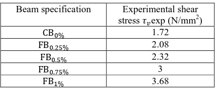
4.4 Shear Stress
The experimentally obtained shear stress is shown in table 15 from the table it can seen that increasing the fibre volume leads to an increase in shear stress. For %fibre the shear stress increased to 53%.
Table 15. Experimental Shear Stress
Beam specification Experimental shear stress 𝜏𝑣exp (N/mmP
2
P
)
CB0% 1.72
FB0.25% 2.08
FB0.5% 2.32
FB0.75% 3
FB1% 3.68
5. Conclusion
An experimental investigation was carried out to study the affect of steel fibres on the shear behavior of high strength concrete beams subjected to 2- point loading and to develop an equation to predict the shear strength of high strength fibre reinforced concrete beams. A total of 15 specimens were cast and tested for the present investigation. Based on the experimental and analytical studies conducted, the following conclusions are arrived.
• The addition of fibres in high strength concrete increases the first crack load and ultimate load. For1% volume fibre the ultimate load increased by 42%.
• For 1% fibre the energy absorption capacity increased by 75.5% and toughness index increased by 42.3%
• Inclusion of steel fibres in the concrete mix improves the shear strength of RC beams and tends to change the mode of failure from brittle shear to ductile flexure.
6. REFERENCES
1)R.Narayanan, I.Y.S.Darwish, Use of steel fibres as shear reinforcement, ACI Structural journal, vol.102, 1987, pp 141-149.
2)R.Narayanan, I.Y.S.Darwish, Fibre concrete deep beams in shear, ACI Structural journal, vol.89, 1988, pp 216-227.
3)Suresh Chand, S.S Rehsi, S.K.Garg, M.Khalid, structural behavior of steel fibre reinforced concrete building components, The Indian Concrete Journal, 1991, pp 339-343.
4)EI-Niema, Reinforced concrete beams with steel fibres under shear, ACI Structural journal, vol. 88, 1991, pp 178-183.
5)Victor C Li, Robrt Ward,Ali M Hamaza, steel and synthetic fibres as shear reinforcement, ACI Material journal, vol 82, 1992, pp 400-508.
6)Samir A Ashour, Ghazi S Hasanain, Fasil F Wafa, Shear Behaviour of High Strength Fibre Reinforced concrete Beams, ACI Structural journal, vol 89, 1992, pp 176-184.
7) Perry Adebar, Sidney Mindess, Daniel St.Pierre and Brent Olund, Shear test of fibre concrete beams without stirrups, ACI Structural Journal, vol 94, 1997, pp 68-77.
8) Madhusudan Khuntia, Bozidor Stojadinovic,and Subhash C, Shear Strength of normal and high strength fibre reinforced concrete beams without stirrups, ACI structural journal, vol. 96, 1999, pp281-291
9) Yoon Keun Kwak, Mark O Eberhard, Woo-Suk Kim, Jubum Kim, Shear strength of steel fibre -reinforced concrete beams without stirrups, ACI Structural journal, vol.99,2008, pp.530-538