● In Edit ➮Preferences ➮General, set the following:
– Default Magnification = Fit Width
– Display Splash Screen at Startup = Disabled (box not checked) – Display Open Dialog Box at Startup = Disabled (box not checked)
● For easiest reading on-screen, select View ➮Fit Width (or Ctrl K). This option
is automatically enabled if you set the Default Magnification in General Preferences as described above.
● To return to the opening screen at any time, press Home.
To scroll up or down on a page, press PageDown or PageUp. To navigate between pages, press –> or <–.
● To increase the speed with which your Acrobat files load, try one of the following:
– In Windows 3.1, add ACROREAD.EXE to your Startup Group (with the Run
Minimized box checked).
– In Windows 95, add ACROREAD.EXE to the Windows\Start
Menu\Programs\StartUp folder (with Run Minimized selected).
● Provides on-line viewing and printing.
● Extensive search and navigation capabilities.
● Ensures more timely turnaround of documents.
● When we provide an Acrobat manual with a product (e.g., Nitsuko TAPI Driver),
you are assured of having the most up-to-date manual available.
● With the installation of a PC fax/modem, it makes faxing of any brochure, user guide, proposal or manual quick and easy.
● Acrobat Reader programs for Macintosh, DOS and UNIX platforms also can be
provided, if required.
● For Technical Support for the Acrobat Reader, contact:
Adobe Systems, Inc.
1585 Charleston Road P.O. Box 7900
Mountain View, CA 94039-7900 Telephone Number: 415-961-4400
Adobe FaxY1 (technical/product information by fax): 206-628-5737 Adobe Electronic Bulletin Board (on-line information): 206-623-6984
URL: http://www.adobe.com
● To return to the opening screen, press the HOME key.
Contents
●
Installing the KSU
●
PCB Installation and Startup
●
Installing Extensions and Trunks
●
Installing Optional Equipment
●
Specifications and Parts List
Hardware Manual
This manual has been developed by Nitsuko America. It is intended for the use of its customers and service personnel, and should be read in its entirety before attempting to install or program the system. Any comments or suggestions for improving this manual would be appreciated. Forward your remarks to:
Nitsuko America, Telecom Division 4 Forest Parkway
Shelton, CT 06484
Attention: Manager, Technical Publications
Nothing contained in this manual shall be deemed to be, and this manual does not constitute, a warranty of, or representation with respect to, any of the equipment covered. This manual is subject to change without notice and Nitsuko America has no obligation to provide any updates or corrections to this manual. Further, Nitsuko America also reserves the right, without prior notice, to make changes in equipment design or components as it deems appropriate. No representation is made that this manual is complete or accurate in all respects and Nitsuko America shall not be liable for any errors or omissions. In no event shall Nitsuko America be liable for any incidental or consequential damages in connection with the use of this manual. This document contains proprietary information that is protected by copyright. All rights are reserved. No part of this document may be photocopied or reproduced without prior written consent of Nitsuko America.
©1997 by Nitsuko America. All Rights Reserved. Printed in U.S.A.
Section 1
Installing the KSU
In this section
. . . PageInstalling the Cabinet . . . .1-3 Unpacking . . . 1-3 Before Installing . . . 1-3 Site Requirements . . . 1-3 Removing the Covers . . . 1-4 Mounting the Cabinet . . . 1-4 Grounding the Cabinet . . . .1-6 Connecting the Ground Wires. . . 1-6
1. Installing the KSU
1. Installing the KSU
INSTALLING THE CABINET
Unpacking
Unpack the equipment and check it against your equipment lists. Inspect for physical damage.
Have the appropriate tools for the job on hand, including: a test set, a punch down tool and a digital voltmeter.
Before Installing
Make sure you have a building plan showing the location of the common equipment, extensions, the telco demarca-tion and earth ground. In addidemarca-tion, the installademarca-tion site must meet the requirements outlined in the Standard Practices Manual.
Site Requirements
The common equipment is contained in a wall-mounted cabinet: the KSU. Choose a central location for the cabinet that allows enough space for the equipment — and provides enough room for you to comfortably work. The Installation
Layout (Figure 1-2 on page 1-5) shows you approximately
how much space your system requires.
The KSU requires a three-prong dedicated 110 VAC 60 Hz circuit (NEMA 5-15 receptacle) located within 6 feet of the AC receptacle. You should install the extension block to the right of the KSU. Telco should install the RJ11C to the left of the KSU.
INSTALLING THE CABINET
Removing the Cover (Figure 1-1)
1. Loosen the screw located on the right-hand side of the cabinet.
2. Slide the cover in the direction of the arrow while press-ing the marked postion slightly.
This allows access to the station and line connec-tors. To have access to PCB’s, you must then remove the main cover.
3. Loosen the two screws located on the top right and bot-tom right of the cabinet.
4. Lift the cover and slide it slightly in the direction of the arrow to remove.
Figure 1-1 REMOVING THE COVER
Mounting the Cabinet
1. Using suitable fasteners, mount a Main Distribution Frame (MDF) plywood backboard in a centrally located spot.
2. Tape the template that is included with the cabinet on the backboard at the desired location. Make sure the tem-plate is level.
If the template is not available, the top two screws should be 11 1/4” apart. The bottom two screws should be 7 1/8” below the top screws, at the same distance apart.
82500 - 19
Screw for Main Cover Screw for
Right Cover
Screw for Main Cover Top Cover
Base Unit
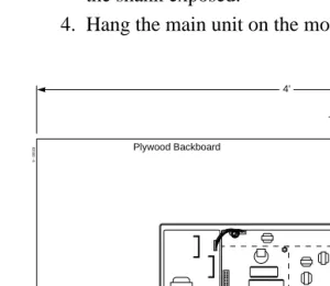
3. Using the template as a guide, install the four mounting screws into the backboard. Leave approximately 1/4” of the shank exposed.
4. Hang the main unit on the mounting screws.
Figure 1-2 INSTALLATION LAYOUT
82500 - 6
RJ11C Jacks
Surge Protector
To Verified Earth Ground
To Stations Station Blocks Auxiliary Blocks To Optional Equipment
Plywood Backboard
4'
2'
From Telco
Dedicated AC Outlet
625 Jacks
INSTALLING THE CABINET
GROUNDING THE CABINET
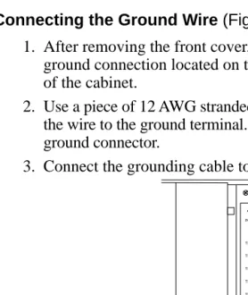
Connecting the Ground Wire (Figure 1-3)
1. After removing the front cover, loosen the lug on the ground connection located on the lower right-hand side of the cabinet.
2. Use a piece of 12 AWG stranded copper wire and connect the wire to the ground terminal. Tighten the lug on the ground connector.
3. Connect the grounding cable to a known earth ground.
Figure 1-3 GROUNDING A CABINET
Now that your cabinet is installed and grounded, go to Part
2: PCB Installation and Startup.
82500 - 9
TEL1
TEL2
TEL3
TEL4
TEL5
TEL6
TEL7
TEL8 INT
CO1 CO2 CO3
Grounding Cable
Section 2
PCB Installation and Startup
In this section
. . . PagePCB Location . . . .2-3 Where to Install the PCB’s . . . .2-3 Installing PCB’s . . . .2-4 Central Processing Unit (CPU) PCB . . . .2-4 SMDR PCB . . . .2-5 SMDR RS-232C Cable . . . .2-6 Auxiliary (3DHEXU) PCB . . . .2-8 Caller ID (3CIDU) PCB . . . .2-9 Fax (3FAXU) PCB . . . .2-10 Powering Up The System . . . .2-12 Power Up Sequence . . . .2-12
2. PCB Installation and
Startup
2. PCB Installation and
Startup
PCB LOCATION
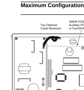
Where to Install the PCBs (Figure 2-1)
Maximum Configuration: 3 Trunks 8 Extensions
Figure 2-1 PCB LOCATION
82500 - 5
TEL8
CO1
EXPCN
OFF
SW2
(MOH)
ON
CO2
CO3
COCN
ETHCN INT
SW1
TEL7
TEL6
TEL5
TEL4
TEL3
TEL2
TEL1
Two Optional Cards Maximum
SMDR PCB, Auxiliary PCB,
or Fax/DISA PCB Caller ID PCB
CPU
INSTALLING PCBs
Central Processing Unit (CPU) PCB (Figure 2-2)
Figure 2-2 CPU PCB
The CPU PCB comes already installed in the KSU. The CPU provides:
● The system’s central processing, stored program and
memory for the customer’s site-specific data.
● Mode switch for cold (default data) or warm (customer
data) start on power-up.
● Battery for backup of the customer’s site-specific data.
The battery’s life is between 3.5 and 7 years - depending on how often the system is powered down. The more the system’s power is off, the shorter the battery’s life.
● Connection points for the CO and station DDK
connec-tors.
82500 - 20
Station 1 Initialization Switch Battery
Station 2 Station 3 Station 4 Station 5 Station 6 Station 7 Station 8 Trunk 1 Trunk 2 Trunk 3 Not Used
Earth Ground
INSTALLING PCBs
To prepare the CPU PCB:
1. Slide the INT switch (SW1) to the left (toward INT).
This ensures that the system will load the default database on initial power-up. Approximately 10 sec-onds after initial power-up, you must change the SW1 switch to the right.
Refer to Part 3, Installing Extensions and Trunks for instructions on connecting the stations and trunks.
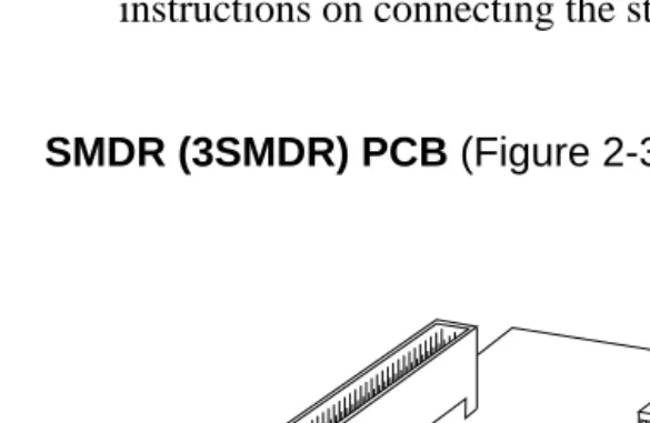
SMDR (3SMDR) PCB (Figure 2-3)
Figure 2-3 SMDR PCB
The SMDR (Station Message Detail Recording) PCB pro-vides a record of the system’s outside calls. Typically, the record outputs to a customer-provided printer, terminal or SMDR data collection device. Use SMDR when you need
82500 - 15
SW1
Baud Rate Setting RSCN
1200 2400 4800 9600
INSTALLING PCBs
Note: The Portrait 308 system can accommodate any combination of optional cards, but the system capacity can not exceed two optional cards.
To install a SMDR PCB:
1. Align the 3SMDR PCB over the connector labeled EXPCN on the CPU or other installed optional PCB. 2. Press the PCB into the EXPCN connector.
3. Using the two metal spacers included with the 3SMDR PCB, attach the PCB to the CPU or other installed optional card.
4. Connect the RS-232C cable into the 3SMDR PCB. 5. Locate the filler pieces on the lower portion of the base
of the KSU. Using a flat-blade screwdriver, carefully pry out the filler piece on the right.
6. Secure the RS-232C cable with the cable tie. Route the cable through hole in the the cabinet.
7. Attach the other end of the RS-232C cable to the printer. 8. Set the interface conditions of the printer as follows:
Word length: 7 bit Start bit length: 1 bit Parity bit: Even parity Stop bit length: 2 bit
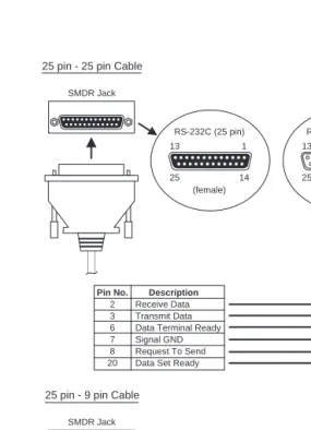
SMDR RS-232C Cable (Figure 2-4)
To connect the SMDR and printer, an RS-232C cable is required. To make your own cable, it must be a straight-through cable connecting pins 2, 3, 6, 7, 8 and 20. Refer to the Figure 2-4.
Note that the cable length should not exceed 50’ in length.
INSTALLING PCBs
Figure 2-4 RS-232C CABLE
SMDR Jack SMDR Jack Pin No. 2 3 6 7 8 20 Pin No. 2 3 6 7 8 20 Pin No. 2 3 6 7 8 20 Pin No. 3 2 6 5 1 4 Receive Data Transmit Data Data Terminal Ready Signal GND Request To Send Data Set Ready
Receive Data Transmit Data Data Terminal Ready Signal GND Request To Send Data Set Ready
Receive Data Transmit Data Data Terminal Ready Signal GND Request To Send Data Set Ready
Transmit Data Receive Data Data Set Ready Signal GND Data Carrier Detect Data Terminal Ready
Description
Description
* The other Pins are not used. These Pin conditions are "Open".
Description
Description
Output Terminal
Output Terminal RS-232C (25 pin)
RS-232C (25 pin)
RS-232C (25 pin)
RS-232C (9 pin) (female) (female) (male) (male) 13 13 13 1 25 25 25 6 1 1 1 5 14 14 14 9 25 pin - 25 pin Cable
25 pin - 9 pin Cable
82400 - 31
INSTALLING PCBs
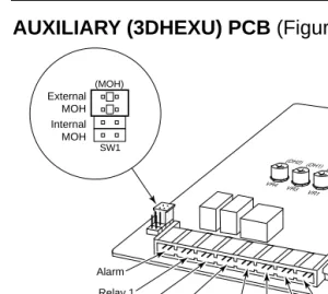
AUXILIARY (3DHEXU) PCB (Figure 2-5)
Figure 2-5 Auxiliary PCB
The optional Auxiliary PCB provides:
● Connections for one alarm sensor
● Connections for customer-supplied Music On Hold
● Two Door Box interfaces
● One External Paging output with SPST relay contact
● Two common-use relay contacts
Note: The Portrait 308 system can accommodate any combination of optional cards, but the system capacity can not exceed two optional cards.
As the Auxliary PCB does not have an EXPCN connector, when using this PCB, it must be placed on top of any other optional PCB.
To install an Auxiliary PCB:
1. Align the 3DHEXU PCB over the connector labeled EXPCN on the CPU or other installed optional PCB. 2. Press the PCB into the EXPCN connector.
(MOH) External MOH Internal MOH Alarm Relay 1 Volume controls for Door Boxes and External Paging
Relay 2 Control for External Paging Amplifier External Paging Speaker External Music on Hold Door Box 1 Door Box 2 SW1
82500 - 16
INSTALLING PCBs
3. Using the two metal spacers included with the 3DHEXU PCB, attach the PCB to the CPU or other installed optional card.
Refer to Part 4: Installing Optional Equipment for more on installing Door Boxes, External Paging Equipment, and Alarm Sensors.
CALLER ID (3CIDU) PCB (Figure 2-6)
Figure 2-2 Caller ID PCB
The optional Caller ID PCB provides:
● Connections for three CO lines to provide Caller ID
capa-bility to display telephones.
Note: The Portrait 308 system can accommodate any combination of optional cards, but the system capacity can not exceed two optional cards.
The Caller ID PCB must be the first optional PCB installed on the CPU.
82500 - 17 COCN1
COCN2 COCN3
INSTALLING PCBs
To install a Caller ID PCB:
1. Place the two nylon spacers included with the 3CIDU PCB in the holes on the right-hand side on the CPU. 2. Align the 3CIDU PCB over the connector labeled
EXPCN and the metal and nylon spacers on the CPU. If
another optional card is already installed, it should be taken out and reinstalled on top of the 3CIDU PCB.
3. Press the PCB into the EXPCN connector and press the PCB into the nylon spacers until they snap into place. 4. Using the two metal spacers included with the 3CIDU
PCB, attach the PCB to the CPU.
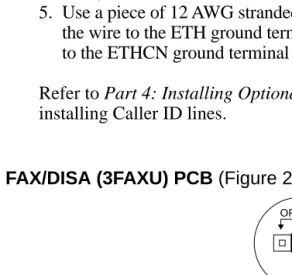
5. Use a piece of 12 AWG stranded copper wire and connect the wire to the ETH ground terminal on the 3CIDU PCB to the ETHCN ground terminal on the CPU.
Refer to Part 4: Installing Optional Equipment for more on installing Caller ID lines.
FAX/DISA (3FAXU) PCB (Figure 2-7)
Figure 2-7 Fax PCB
82500 - 18
RUN
TEST
JP2 OFF
ON JP1
INSTALLING PCBs
The optional Fax/DISA PCB provides:
● Capability of installing one fax machine to an extension
port to detect the CNG signal from an incoming fax.
● Interface for DISA capability.
Note: The Portrait 308 system can accommodate any combination of optional cards, but the system capacity can not exceed two optional cards.
To install a Fax/DISA PCB:
1. Align the 3FAXU PCB over the connector labeled EXPCN and the metal spacers on the CPU or other installed optional card.
2. Press the PCB into the EXPCN connector.
3. Using the two metal spacers included with the 3FAXU PCB, attach the PCB to the CPU or other installed optional card. 4. Move the jumper from the JP1 connector to the ON side
(Figure 2-7).
5. Move the jumper from the JP2 connector to the RUN side (Figure 2-).
Refer to Part 4: Installing Optional Equipment for more on installing a fax machine to the system.
POWERING UP THE SYSTEM
Power-Up Sequence
Now that all the PCBs you need are installed, you can power-up the system.
1. Install a surge protector in the AC outlet you intend to use for system power.
2. Set the initialization switch to the left side.
3. Plug the AC power cord for the KSU into its surge pro-tector.
4. Wait approximately 10 seconds, then move the initializa-tion switch to the right.
System LEDs on Power-Up
PCB LED Status
CPU Processor LED About 5 seconds after power-up,
(Red) flashes quickly.
Power LED Lit steadily when the CPU has
(Green) power.
Section 3
Installing Extensions and Trunks
In this section
. . . PageConnecting Blocks . . . .3-3 Working With DDK Connectors . . . .3-3 Making Additional DDK Connectors . . . .3-3 Punching Down a DDK Installation Cable . . . . .3-4 Connecting Extensions . . . .3-7 Station Connections . . . .3-7 Connecting Trunks . . . .3-10
Trunk Connections . . . .3-10 3. Installing Extensions
and Trunks
3. Installing Extensions
and Trunks
CONNECTING BLOCKS
Working With DDK Connectors
The system uses DDK-type connectors for extensions, trunks and optional equipment. Using the optional DDK Installation Cables (4-pin station cable=P/N 82490, 2-pin C.O. line cable=P/N 82492) makes it easy to connect the PCBs to standard 66M1-50 connecting blocks. The cables available for the system are for CO lines (one-pair), keysets (2-pair), and auxiliary options (one-pair). If desired, sepa-rate DDK connectors without cable can be purchased. In general, each cabinet needs:
● One 66M1-50 block and DDK Installation Cable for extensions.
● One 66M1-50 block and DDK Installation Cable for optional equipment
● Up to three (depending on your requirements) RJ11C modular jacks and one DDK Installation Cable for trunks.
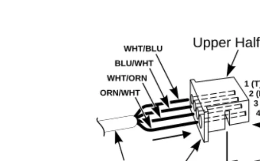
Making Additional DDK Connectors (Figure 3-1)
To make DDK connectors, using 22 or 24 gauge solid 2-pair twisted wire for keysets or 22 or 24 gauge solid 1-pair twist-ed wire for CO lines, single line telephones, Power Failure, or auxiliary functions, do the following:
1. Do not strip the wires. Insert the wires into the top piece (clear plastic) of the connector. Following the standard color code:
#1=White/Blue #2=Blue/White, #3=White/Orange #4=Orange/White (Ignore #3 and #4 if only using 1-pair twisted wire) Refer to Figure 3-4 for additional help with the color code. Make sure that the wire ends do not protrude beyond the rear end of the connector.
2. Place the top half of the connector over the lower half and press down or use pliers to snap together. Verify that the connector will not come apart and that all the wires are secure. Once together, these connectors will not sepa-rate without breaking.
CONNECTING BLOCKS
Figure 3-1 MAKING DDK CONNECTORS
Punching Down a DDK Installation Cable
The DDK Installation Cables have 4-pin DDK connectors installed on one end and are unterminated on the other. 1. For each 66M1-50 block, punch down the DDK
Installation Cable in standard color-code order.
Refer to Figure 3-3 if you need help with the color code.
2. Make all wire connections required for any optional cards installed.
3. The main cover should then be replaced on the cabinet, with only the right-side cover removed.
This will allow access to make the station and trunk connections.
4. After you have punched down your cables, secure them with the cable holder located on the right-hand side of the KSU (Figure 3-2).
Upper Half
82400 - 30
Approx. 5/16"
Lower Half DDK Connector
Two pair twisted telephone wire
WHT/BLU
BLU/WHT
WHT/ORN
ORN/WHT
1 (T) 2 (R) 3 (H) 4 (L)
CONNECTING BLOCKS
Figure 3-2 SECURING THE CABLES
82500 - 8
TEL1
TEL2
TEL3
TEL4
TEL5
TEL6
TEL7
TEL8 INT
CO1 CO2 CO3
CONNECTING BLOCKS
Figure 3-3 CONNECTING BLOCK
No Connection No Connection No Connection No Connection No Connection
T R H L
= Tip = Ring = High = Low
82500 - 4
(DDK Pin 1) (DDK Pin 2) (DDK Pin 3) (DDK Pin 4)
CONNECTING EXTENSIONS
Station Connections (Figure 3-4)
The CPU has 4-pin DDK connectors for eight stations. The stations can be a combination of keysets or single line tele-phones, but the system can only accept a maximum of six single line telephones (ports 10 and 11 can only use keysets).
Refer to Part 4: Installing Optional Equipment for instructions on connecting a power failure telephone.
Figure 3-4 STATION CONNECTIONS
1. Following the conventional color code, insert the DDK connectors into the PCB. For example, the eight stations in the system would have these connections:
Ext./Port DDK Connector Pair
10 WHT-BLU / BLU-WHT / WHT-ORN / ORN-WHT 11 WHT-GRN / GRN-WHT / WHT-BRN / BRN WHT 12 WHT-SLT / SLT-WHT / RED-BLU / BLU-RED 13 RED-ORN / ORN-RED / RED-GRN / GRN-RED 14 RED-BRN / BRN-RED / RED-SLT / SLT-RED 15 BLK-BLU / BLU-BLK / BLK-ORN / ORN-BLK 16 BLK-GRN / GRN-BLK / BLK-BRN / BRN-BLK 17 BLK-SLT / SLT-BLK / YEL-BLU / BLU-YEL
Note that single line telephones only use one-pair wire (T/R). When installing a single line set, the second pair is
82500 - 8
TEL1
TEL2
TEL3
TEL4
TEL5
TEL6
TEL7
TEL8 INT
CO1 CO2 CO3
CONNECTING EXTENSIONS
2. Install a modular jack for each extension within six feet of the telephone’s location. See Figure 3-5.
3. For each keyset, run two-pair 24 AWG station cable from the cross-connect block to the modular jack. For each single line phone, run one-pair 24 AWG station cable from the cross-connect block to the modular jack. 4. Terminate the station cable to the modular jack lugs:
WHT-BLU to GREEN lug BLU-WHT to RED lug WHT-ORN to BLACK lug * ORN-WHT to YELLOW lug *
* Lug not used when installing a single line phone. 5. Back at the MDF, run two pairs of cross-connect wires
(or one pair of cross-connect wires for single line phones) between the pins on the B block and cross-con-nect block to complete the concross-con-nection.
6. Install bridging clips as required.
7. After completing step 6, you should be able to place and answer calls at the extension.
Figure 3-5 CONNECTING KEYSET TELEPHONES
625 Modular Jack
DDK Installation Cable
BLK YEL RED GRN BLU-WHT ORN-WHT WHT-ORN WHT-BLU Cross Connect Block Two Pair Cross Connect "B" Block
CONNECTING EXTENSIONS
Figure 3-6 CONNECTING SINGLE LINE TELEPHONES
625 Modular Jack
Power Failure Telephone
BLK YEL
RED GRN
BLU-WHT WHT-BLU
One-Pair Cross-Connect
25-Pair DDK Installation Cable
"C" Block Cross
Connect Block
82400 - 2
CONNECTING TRUNKS
Trunk Connections (Figure 3-7)
The CPU has 2-pin DDK connectors for three loop start CO trunks.
Refer to Part 4: Installing Optional Equipment for instructions on connecting a power failure tele-phone.
Figure 3-7 TRUNK CONNECTIONS
1. Following the conventional color code, insert the DDK connectors into the PCB. For example, the CPU would have these connections:
Trunk DDK Connector Pair
1 WHT-BLU / BLU-WHT
2 WHT-ORN / ORN-WHT
3 WHT-GRN / GRN-WHT
2. For each trunk, run one pair of wires from the DDK con-nection to a 625 modular jack, which then connects to the telco’s RJ11C jacks using a standard line cord (Figure 3-8 on the following page).
3. After completing step 2, you should be able to place and answer calls over the connected trunk.
82500 - 8
TEL1
TEL2
TEL3
TEL4
TEL5
TEL6
TEL7
TEL8 INT
CO1 CO2 CO3
CONNECTING TRUNKS
Figure 3-8 CONNECTING TRUNKS
82500 - 2
To CO connector on CPU
DDK
Connector 25-Pair DDK Installation Cable
625 Modular
Jack
Line Cord
To Central Office Telco RJ11C
BLU-WHT WHT-BLU
RED GRN
For Your Notes
Section 4
Installing Optional Equipment
In this section
. . . . . . .PageAlarm Sensors . . . .4-3 Using External Alarm Sensors . . . .4-3 Installing an External Alarm Circuit . . . .4-3 External Paging and Page Relays . . . .4-5
Using External Paging . . . .4-5 Installing External Paging and Page Relays . . . .4-5 Door Box . . . .4-8
Using the Door Box . . . .4-8 Installing a Door Box . . . .4-8 Installing Door Strike Control Relays . . . .4-10 Music Sources . . . .4-12
Music on Hold . . . .4-12 Installing a Music Source on an Auxiliary PCB . . .4-12 Caller ID . . . .4-14
Using the Caller ID Feature . . . .4-14 Connecting Caller ID . . . .4-14 Programming . . . .4-15 Fax/DISA . . . .4-18
Fax Connections . . . .4-18 Programming . . . .4-19 Preparing the Automated Attendant Message . . . . .4-21 Power Failure Telephones . . . .4-23
Power Failure Cut-Through . . . .4-23 Voice Mail . . . .4-25
Using Voice Mail . . . .4-25 Programming . . . .4-26 Wall-Mount Kit . . . .4-28
Using the Wall-Mount Kit . . . .4-28 Installing the Wall-Mount Handset Hanger . . . .4-28 Wall-Mounting a Key Telephone . . . .4-29
4. Installing Optional
Equipment
4. Installing Optional
Equipment
ALARM SENSORS
Using External Alarm Sensors
The Auxiliary (3DHEXU) PCB provides one alarm circuit which detects a make (open) or break (closed) contact from an alarm. Programming determines if the alarm input requires an open or closed circuit.
An alarm detection causes the system to send a signal to sta-tions programmed to receive the alarms. The alarm signal can also be sent to external paging speakers.
Installing an External Alarm Circuit (Figure 4-1)
CAUTION
Be sure the requirements of the alarm system sensors do not exceed the system specifications of a loop resistance of less than 100 Ohms.
1. Locate an available 2-pin DDK connector in an auxiliary (C) block.
2. For the DDK connector chosen, cross-connect the associ-ated wire pair from the C block to the cross-connect block. 3. Install bridging clips as required.
4. Connect the two leads from the external alarm to the associated terminals on the cross-connect block.
5. Plug the DDK connector into the ARM connector on the Auxiliary PCB.
6. Set whether the alarm circuit is normally open or closed in Program 44. In system programming, enter the following:
1 * 1 * then either 1 or 0
The above entry sets the following: 1 (Alarm 1) * (enter information) 1 (Activate Alarm) * (enter information) then either 1 (Normally open circuit) or 0 (normally closed cir-cuit).
ALARM SENSORS
Figure 4-1 CONNECTING AN ALARM
Figure 4-2 CONNECTING TO THE AUXILIARY PCB
82500 - 14
Auxiliary PCB
Alarm Input DH2 DH1 EXMOH SPK CTR RL2 RL1 ARM (MOH)
EXT
INT
SW1
One-Pair Cross-Connect
DDK Connector To alarm input on Auxiliary PCB
25-Pair DDK Installation Cable
"C" Block Cross
Connect Block
Input from alarm system
82400 - 11
EXTERNAL PAGING AND PAGE RELAYS
Using External Paging
The Auxiliary PCB has one External Paging audio output and one associated control relay. You connect the audio out-put to the audio inout-put on customer-provided paging systems. In some paging systems, you can use the control relay to automatically turn the amplifier on and off. The control relay is normally opened and closes whenever a user calls the External Paging zone.
Installing External Paging and Page Relay (Figure 4-4)
CAUTION
Be sure the audio input requirements of the paging equipment are compatible with the audio output specifications of the sys-tem.
Output Impedance: 600 Ohms
Output Level: Nominal 250 mV (-10 dBm) Maximum Output: 400 mV RMS
Minimum Initial Contact Resistance: 50 mOhms Relay Contact: 250 mA @ 24 VDC
1. Locate an available 2-pin DDK connector in an auxiliary (C) block.
2. For the DDK connector chosen, cross-connect the associ-ated wire pair from the C block to the cross-connect block. 3. Install bridging clips as required.
4. Connect the lead to the paging system audio input. 5. Plug the DDK connectors into the Auxiliary PCB. One
connector is plugged into the connector on the PCB labeled SPK, the other goes to CTR.
6. Adjust the volume level of the External Zone by turning the VR1 control (also labeled SPK).
EXTERNAL PAGING AND PAGE RELAYS
Figure 4-4 CONNECTING EXTERNAL PAGING/RELAY
Figure 4-5 CONNECTING EXTERNAL PAGING
One-Pair Cross-Connect
DDK Connector To External Page audio output on Auxiliary PCB
25-Pair DDK Installation Cable
"C" Block Cross Connect
Block
Output to paging system control inputs
82400 - 10
One-Pair Cross-Connect
DDK Connector To Control Relay on Auxiliary PCB
25-Pair DDK Installation Cable
"C" Block Cross
Connect Block
Output to paging system control inputs
82400 - 9
EXTERNAL PAGING AND PAGE RELAYS
Figure 4-6 CONNECTING CONTROL RELAYS TO THE AUXILIARY PCB
82500 - 13
Auxiliary PCB
DH2 DH1 EXMOH SPK CTR RL2 RL1
(DH2) (DH1) (SPK)
VR4 VR3 VR1
ARM (MOH) EXT INT
SW1
Amplifier Paging Speaker
DOOR BOX
Using the Door Box
Each Auxiliary PCB supports two Door Boxes. In addition, you can connect each circuit’s control relay to an electric door strike. This allows an extension user to remotely activate the door strike while talking to a visitor at the Door Box. The control relays are normally open.
Installing a Door Box (Figure 4-7)
1. Locate an available 2-pin DDK connector in an auxiliary (C) block.
2. For the DDK connector chosen, cross-connect the associated wire pair from the C block to the cross-connect block. 3. Connect leads from lugs 1 and 2 on the Door Box to the
cross-connect block. Be sure to maintain the proper polarity. 4. Plug the DDK connector into the Door Box (1 or 2)
con-nector on the Auxiliary PCB. The first Door Box is labeled DH1 on the PCB. The second Door Box is labeled DH2. 5. Install bridging clips as required.
6. Use VR3 or VR4 on the CPU to adjust the volume of the Door Box. VR3 corresponds to Door Box 1, VR4 corre-sponds to Door Box 2.
DOOR BOX
Figure 4-7 CONNECTING A DOOR BOX
1 5
6 L
C T
T
2 3 4
L F
To Door Chime Box 1 Rear view
To Door Chime Box 2 21
22 23 24
* typical installation RED-BRN
BRN-RED RED-SLT SLT-RED *
*
Misc Block
Holes for mounting screws
9
2
0
-
1
5
9
A
DOOR BOX
Installing Door Strike Control Relays (Figure 4-8)
CAUTION
Be sure the requirements of the door strike are compatible with the control relay output specifications of the system.
Contact Configuration: Normally open Maximum Load: 250 mA @ 24 VDC
Maximum Initial Contact Resistance: 50 mOhms
1. Locate an available 2-pin DDK connector in an auxiliary (C) block.
2. For the DDK connector chosen, cross-connect the associ-ated wire pair from the C block to the cross-connect block.
3. Connect two leads from the door strike to the associated terminals on the cross-connect block.
If the door strike is a high current device, you may have to install an auxiliary relay that powers the door strike relay.
4. Plug the DDK connector into the Auxiliary PCB connec-tor labeled RL1 or RL2. RL1 controls the door strike relay for Door Box 1, RL2 controls Door Box 2. 5. Install bridging clips as required.
6. In Program 56 assign a relay to a door box.
DOOR BOX
Figure 4-8 CONNECTING TO THE DOOR STRIKE
Figure 4-9 CONNECTING DOOR BOX/DOOR STRIKE RELAYS TO THE AUXILIARY PCB
82500 - 12
Auxiliary PCB
To Door Strike Terminals
DH2 DH1 EXMOH SPK CTR RL2 RL1
(DH2) (DH1) (SPK)
VR4 VR3 VR1
ARM (MOH)
EXT
INT
SW1
Door Box
One-Pair Cross-Connect
DDK Connector To Control Relay on Auxiliary PCB
25-Pair DDK Installation Cable
"C" Block Cross
Connect Block
Output to door strike
82400 - 8
MUSIC SOURCES
Music on Hold
Music on Hold (MOH) provides music to callers on Hold. The system’s default setting provides an internal (synthe-sized) MOH music source, or a customer-provided music source connected to the Auxiliary PCB can be used instead.
There are two jumpers that determine whether or not the system will play Music on Hold. The first jumper is located on the CPU and is labeled SW2. This jumper should be set to the ON position. If it is not, it overrides the setting of the SW1 jumper on the Auxiliary PCB (3DHEXU-A).
Installing a Music Source on the Auxiliary PCB
(Figure 4-10)
CAUTION
Be sure the music source is compatible with the MOH input specifications on the CPU PCB.
Input Impedance: 600 Ohm
Input Level: Nominal 250 mV (-10 dBm) Maximum Input: 1V RMS
1. Locate an available 2-pin DDK connector in an auxiliary (C) block.
2. For the DDK connector chosen, cross-connect the associat-ed wire pair from the C block to the cross-connect block. 3. Connect two leads from the customer-provided music source
to the associated terminals on the cross-connect block. 4. Plug the DDK connector into the EXMOH input on the
Auxiliary PCB.
5. Set the SW1 (MOH) jumper on the Auxiliary PCB to the EXT position. Make sure the SW1 jumper on the CPU is set to the ON position. If synthesized MOH is desired, set the SW1 (MOH) jumper on the Auxiliary PCB to the INT position.
6. Install bridging clips as required.
MUSIC SOURCES
Figure 4-10 CONNECTING MUSIC SOURCES
82500 - 11
External MOH Source Auxiliary PCB
The relay contacts RL1 and RL2 can be used as a MOH device control. The remote control terminal on the device must be connected to these contacts (see PROGRAM 56). DH2 DH1 EXMOH SPK CTR RL2 RL1
(DH2) (DH1) (SPK)
VR4 VR3 VR1
ARM (MOH)
EXT
INT
SW1
82500 - 3
One-Pair Cross-Connect
To MOH on Auxiliary PCB
To music source
DDK
Connector 25-Pair DDK Installation Cable
"C" Block Cross Connect
Block
CALLER ID
Using the Caller ID Feature
Each Auxiliary PCB supports the use of Caller ID on the three CO lines in the system. Caller ID allows a display key-set to show an incoming caller’s telephone number and/or name with the time and date on the phone’s display. The caller’s information can be checked before answering an incoming call. The information received by the system depends upon the capabilities of your local telco.
Connecting Caller ID (Figure 4-12)
1. With two 2-pin DDK connectors (one connected on each end of the cable), make a jumper cable about 8” in length. If more than one Caller ID line is to be connect-ed, make a jumper cable for each line.
2. For the first line, plug one end of the jumper cable into the COCN1 connector labeled “4” on the Caller ID PCB.
Repeat this step for lines 2 (COCN2) and 3 (COCN3).
3. Plug the opposite end of the jumper cable into the COCN connector labeled CO1 on the CPU.
Repeat this step for lines 2 (CO2) and 3 (CO3).
4. For each trunk, run one pair of wires from the COCN1 connector labeled “1” on the Caller ID PCB to a 625 modular jack, which then connects to the telco’s RJ11C jacks using a standard line cord (Figure 4-12 on the fol-lowing page).
Repeat this step for lines 2 (COCN2) and 3 (COCN3).
5. Connect a grounding cable from the ETH terminal on the Caller ID PCB to the ETHCN terminal on the CPU. 6. Remove the knock-out panel from the main cover that is
located next to the CO connectors on the CPU.
7. Run the wires for the telco connection through one of the knockouts located on the bottom of the base cabinet. 8. Replace the covers on the cabinet.
CALLER ID
Figure 4-12 CONNECTING CALLER ID
Programming
The following programs affect how the Caller ID and SMDR features operate. Program each one according to your require-ments.
Required Programming
Program 3 - Line Options (2) -- E. Caller ID
This determines if the Caller ID feature is enabled or disabled for the line number entered. [0 = Disabled, 1 = Enabled (default = 0)]
Optional Programming
Program 15 - System Options (1) --E Single Step Access
Designate if an extension user can obtain an outside or ICM dial tone in a single step without lifting the handset or press-ing the SPK key. [0 = Disabled, 1 = Enabled (default = 0)]
NOTE: If Disabled just touch the line key to see the Caller
ID information. If Enabled you must press FLASH
82500 - 10
TEL8
CO1
CO2
CO3
COCN
ETHCN
COCN1 COCN2 COCN3
1 4 1 4
ETH
TEL7
TEL6
TEL5
CPU
Caller ID PCB
Grounding Cable To telco connection
1 4
CALLER ID
Program 58 - SMDR Options (2) -- D. Caller ID Printout Program whether the SMDR will print Caller ID information, and if so, which information will be printed. [0 = Not Printed, 1 = Telephone Number Printed, 2 = Name Printed, 3 = Name Printed, but if Name information is not provided by telco, then
only the Number will print. (default = 0)]
Program 61 - Extension Options (4) -- B. Caller ID Data Indication
Choose whether the station displays the Caller ID data.
[0 = Not Indicated, 1 = Indicated (default = 1)]
Program 61 - Extension Options (4) -- C. Editing the Caller ID Table
Enable or disable a station’s ability to edit the Caller ID table.
[0 = Disabled, 1= Enabled (default = 1)]
Program 64 - System Options (7) -- B. Temporary Memory Status
Assign the status of the Temporary Memory Indication.
[0 = Not Indicated, 1 = Indicated (default = 0)]
Program 74 - Caller ID Timers
Program each of the following timers:
1. Caller ID Information Waiting Timer:
When the system detects a Caller ID signal, the LED of the CO key shows a busy indication. After the pro-grammed time has expired, the LED status goes to a normal incoming call.
[000 = Not Timed Out, 001 - 015 = 1 - 15 seconds
(default = 007)]
2. Incoming Signal Detection Timer:
If an incoming signal continues more than the specified time, the system recognizes the signal as “Incoming”. [000 - 015 = 0 - 1.5 seconds (each number represents a 100 ms step) (default = 001)]
CALLER ID
3. Caller ID Signal Duration Timer:
If the interval between the first incoming signal and the Caller ID signal is more than the specified time, the system accepts the call.
[000 - 015 = 0 - 750 ms (each number represents a 50
ms step) (default = 000)]
4. Caller ID Signal Carrier Detection Timer:
If the carrier signal of Caller ID continues more than the specified time, the system accepts the call.
[000 - 008 = 500 - 900 ms (each number represents a
50 ms step), 009 - 014 = 1s - 2s (each number
repre-sents a 200 ms step) (default = 015)]
000 = 500 ms 008 = 900 ms
001 = 550 ms 009 = 1.0 s
002 = 600 ms 010 = 1.2 s
003 = 650 ms 011 = 1.4 s
004 = 700 ms 012 = 1.6 s
005 = 750 ms 013 = 1.8 s
006 = 800 ms 014 = 2.0 s
007 = 850 ms 015 = 3.0 s
Program 93 - Sub-CPU Version
This program indicates the Sub-CPU version for each unit. To view the version number, enter one of the following, then press the * to display the version number (e.g. 93-01 -10 [93=program 01=CPU 10=version number]).
00 = main ROM 01 = CPU
02-09 = not used 10 = Caller ID PCB 11-13 = not used 14 = Fax/DISA PCB
Program 94 - Clear Caller ID Table
Use this program only when you wish to clear all of the information in the Caller ID Table. To clear all information,
FAX/DISA
Fax Connections (3FAXU) (Figure 4-13)
The Fax/DISA PCB allows for the connection of a G3-type fax machine to a station port. It will detect the CNG signal from an incoming fax call and allow the call to be connected automatically to the fax unit. (If a G2-type fax machine is used, an incoming call may not be automatically transferred to the fax machine.)
1. The connection from the modular jack to the CPU requires only one pair, but the DDK connector must a 4-pin connector. The wires should be connected to the tip and ring. Refer to Figure 4-13 for the wiring of the DDK connector.
2. Plug the DDK connector into any available station port on the CPU except TEL1 or TEL2.
3. Install a modular jack within six feet of the fax unit’s loca-tion.
4. Run 24 AWG station cable from the cross-connect block to the modular jack. Using two-pair cable will allow the jack to be either a fax or keyset in the future, if needed, without rewiring the station.
5. Terminate the station cable to the module jack lugs: WHT-BLU to GREEN lug
BLU-WHT to RED lug
6. Back at the MDF, run one pair of cross-connect wires between the pins on the B block and cross-connect block to complete the connection.
7. Make sure the JP1 and JP2 jumpers on the Fax/DISA PCB are set to the proper position. JP1 should be set to “ON” and JP2 should be set to “RUN”.
8. Install bridging clips as required.
9. Plug a line cord from the modular jack to the line port on the fax unit.
10. Plug in the fax unit and turn the power on.
FAX/DISA
Figure 4-13 CONNECTING THE FAX UNIT
Programming
The following programs affect how the FAX feature operates. Program each one according to your requirements.
Required Programming
Program 67 - Fax Assignment (1) Assign the following options:
1. Line Number
Assign the line number to be used for the fax machine. [00=Not assigned, 01-03=Line numbers 01-03 (default = 00)]
2. Station Port
Assign the station port to which the fax machine is con-nected. [00 = Not assigned, 12 - 17 = stations 12-17 (default = 00)]
Optional Programming
Program 68 - Fax Assignment (2)
82500 - 7
FAX/DISA
A. Line Type
Program whether the line is to be used for fax (0), DISA (1) or both (2). The setting here determines whether or not the automated attendant will play the greeting messages. (default = 0)
B. CNG signal is not received
Set how the system should handle a call when the CNG signal is not received. [0=cut off, 1=transfer to opera-tor, 2=transfer to fax (default = 2)]
C. Extension Busy
Program how the system should handle a call when the desired extension is busy. [0=cut off, 1=transfer to oper-ator, 2=resend Attendant Message #2 (default = 0)]
D. Not Used
(default = 0)
E. Not Used
(default = 0)
Program 69 - Fax Assignment (3) Program each of the following timers:
1. Automatic Answer Timer
If the system should not answer the call immediately, but should wait for a specified amount of time, set the timer for the desired delay time. [000 = Immediate answer, 001 - 255 = 1-255 seconds (default = 000)]
2. Waiting Time for CNG Signal Detection
Set how long the system should wait for a CNG signal. [000 = Not assigned, 001 - 255 = 1-255 seconds
(default = 015)]
3. Waiting Time for DTMF Signal Receiving
Program how long the system should wait to receive DTMF signals. [000 = Not assigned, 001 - 255 = 1-255 seconds (default = 010)]
4. Calling Time for Telephone/Fax
Program the calling timer for fax or extensions. [000 = Not assigned, 001 - 255 = 1-255 seconds (default = 030)]
FAX/DISA
Program 75 - Extension Options (5) -- C. Automatic Line Seizing by Fax
Enable or disable the ability for the fax machine to automati-cally seize a line when going off-hook. [0 = Disabled, 1=
Enabled (default = 0)]
Program 93 - Sub-CPU Version
This program indicates the Sub-CPU version for each unit. To view the version number, enter one of the following, then press the * to display the version number (e.g. 93-01 -10 [93=program 01=CPU 10=version number]).
00 = main ROM 01 = CPU
02-09 = not used 10 = Caller ID PCB 11-13 = not used 14 = Fax/DISA PCB
Preparing the Automated Attendant Message
The Fax/DISA PCB provides five automated attendant messages which are used for the fax and DISA features only. Before using either feature, each message must be recorded. These messages can only be recorded at station 10.
Each message’s recording time is fixed and can not be changed. The following chart shows the length of time and sample mes-sage for each mesmes-sage.
Message 1 18 seconds Thank you for calling the XYZ company.
Please hold while your call is being processed. Thank you.
(This is only a greeting message. A caller wishing to send a fax must wait for Message 2 before proceeding.)
Message 2 18 seconds Thank you for calling the XYZ company.
Please dial your extension number between 0 and 7. If you wish to send a fax, please dial # or press the start key now. Thank you.
Note: The extension numbers must be specified as 0 through 7. This corresponds as: 0=extension 10 . . . 7=extension 17.
FAX/DISA
To Record a Message: 1. Lift the handset. 2. Press ICM. 3. Dial 930.
4. Dial the message number (1-5). 5. Press *.
Start recording after dial tone is heard. Make sure to speak clearly.
6. Press * to stop recording.
Pressing # will cancel the recording.
7. Hang up.
To Erase a Message:
1. Lift the handset or press SPK. 2. Press ICM.
3. Dial 931.
4. Dial the message number (1-5). 5. Press *.
A confirmation tone is heard.
6. Hang up.
To Confirm a Message:
1. Lift the handset or press SPK. 2. Press ICM.
3. Dial 932.
4. Dial the message number (1-5). 5. Press *.
The message is played.
6. Hang up.
Message 3 9 seconds You have dialed an incorrect number.
Please enter your extension number again.
Message 4 9 seconds Your call is being transferred to the
opera-tor. Please hold.
Message 5 9 seconds We’re sorry you’re experiencing problems.
Please try your call again later.
POWER FAILURE TELEPHONES
Power Failure Cut-Through (Figure 4-14)
When system AC power fails, the CPU automatically con-nects the first trunk to the Power Failure Telephone (station 17). When the power failure option is used, station 17 must be a single line set. If this option is not used, the station can either be a single line or keyset telephone.
1. Set the SW3 jumper located on the CPU to the PF position. 2. Plug a 2-pin DDK connector into the CO1 connector on
the CPU PCB.
3. Run the wires from the DDK connector to a 625 modular jack, which then connects to the telco’s RJ11C jack using a standard line cord.
4. Install a modular jack for the Power Failure Telephone within six feet of the telephone’s location.
This must be station 17.
5. Plug a 4-pin DDK connector into the TEL8 connector on the CPU.
6. Run the two-pair 24 AWG station cable from the cross-connect block to the Power Failure Telephone’s modular jack.
7. Terminate the station cable WHT/BLU BLU/WHT -WHT/ORN - ORN/WHT leads to the GREEN, RED, BLACK, and YELLOW lugs in the modular jack. 8. Back at the MDF, run two pairs of cross-connect wires
between the pins on the B block and cross-connect block to complete the connection.
8. Install bridging clips as required.
9. Plug a line cord into the Power Failure Telephone and the phone’s modular jack.
No programming is required to enable the Power Failure Telephone.
To test the Power Failure Telephone:
1. Make sure the INT switch on the CPU is set to the right.
This ensures that your programming and configura-tion is retained when you power down the system.
2. Power down the system.
3. At the Power Failure Telephone, lift the handset and place a test call.
POWER FAILURE TELEPHONES
Figure 4-14 CONNECTING A POWER FAILURE TELEPHONE
82500 - 1
Two-Pair Cross-Connect
To TEL8 connector on the CPU
DDK
Connector 25-Pair DDK Installation Cable
"C" Block ConnectCross Block
625 Modular
Jack
Power Failure Telephone
ORN-WHT WHT-ORN
BLU-WHT WHT-BLU
YEL
RED
BLK
VOICE MAIL
Using Voice Mail (Figure 4-15)
The Portrait System is compatible with the NVM-202ex or NVM-22 (P/N 17590A) Voice Mail Systems. This feature provides telephone users with comprehensive Voice
Messaging and Auto Attendant capabilities. The system has a capacity of five voice mail ports.
System Requirements:
● NVM-202ex (P/N 17670) software 6.01 or higher OR
NVM-22 (P/N 17590A) software 7.01 or higher Voice Mail Units.
● Portrait 308 with software version 1.00 or higher.
NOTE: The Voice Mail ports can be any station port other
than ports 10, 11 or 17. The ports do not have the
required loop current and data transmission capability.
● Voice Mail Interface (P/N 82440)
To confirm if your equipment can support voice mail, you can also use Program 93 - Sub-CPU Version in the Portrait sys-tem. The version number of the CPU (Unit 1) should be “10” or above. If the version number is below 10, the CPU can not support the voice mail option.
When active, each voice mail port uses an intercom link. The Portrait system provides two intercom links. When the voice mail ports exceed the available intercom links, intercom calls will be blocked. If only one voice mail port is being used, it must be connected to “LINE1”.
1. Following the conventional color code, insert the DDK connectors into the station port connectors on the PCB.
2. Install a modular jack for each voice mail port within six feet of the voice mail unit.
3. For each voice mail port, run two-pair 24 AWG station cable from the cross-connect block to the modular jack. 4. Terminate the station cable to the modular jack lugs:
WHT-BLU to GREEN lug BLU-WHT to RED lug
VOICE MAIL
ORN-WHT to YELLOW lug
5. Back at the MDF, run two pairs of cross-connect wires between the pins on the B block and cross-connect block to complete the connection.
6. Install bridging clips as required.
7. Using a four-conductor line cord, connect the first modu-lar jack to “LINE1” on the Voice Mail Interface. Then, connect the second modular jack to “LINE2” on the Voice Mail Interface.
If “LINE1” fails due to improper installation for an equipment problem, “LINE2” will not function.
8. Connect a four-conductor line cord from the Port 1 & 2 jacks on the back of the Voice Mail to the “VOICE MAIL” connector on the Voice Mail Interface.
Programming
1. Program 7 - Incoming Line Access/Audible
Use this program to enter the lines that should ring to the Voice Mail.
2. Program 65 - Voice Mail Port
Enter the extension number for each Voice Mail port. 3. Refer to the Voice Mail’s Manual for further programming.
System Manual P/N See
NVM - 22 17590INS** Chapter 1 - Installation
Chapter 2 - Programming
NVM - 202ex 17570SWG** Chapter 2 - Starting Up and
Installing NVM-202ex Chapter 5 - Customizing
System and Port Options
17570INS** Chapter 3 - Starting Up and
Installing NVM-202ex
VOICE MAIL
Figure 4-15 INSTALLING VOICE MAIL BLK
RED GRN
BLU-WHT
ORN-WHT WHT-ORN
WHT-BLU
8240 - 62a
YEL BLK RED GRN BLU-WHT ORN-WHT WHT-ORN WHT-BLU YEL BLU-WHT ORN-WHT WHT-ORN WHT-BLU BLU-WHT ORN-WHT WHT-ORN WHT-BLU 25-Pair Cable to Portrait KSU
Extension Modular Jack Extension Modular Jack Twisted Pair Station Cable
VOICE MAIL INTERFACE
VOICE MAIL LINE2LINE1
4-Conductor Line Cord
NVM-22
Connector for Ports 1 and 2
NVM-202ex
Connector for Ports 1 and 2
WALL MOUNT KITS
Using the Wall-Mount Kit
You can use a wall-mount kit to attach any key telephone to a wall. The wall-mount kit includes a mounting bracket, wall-mount screws and a handset hanger. When a phone is wall-mounted, the directory tray located beneath the phone can not be used.
Note: The wall-mount kit currently does not accommodate
installing on a wall plate.
Installing the Wall-Mount Handset Hanger (Figure 4-16)
1. Insert the handset hanger in the slot provided beneath the telephone’s hookswitch.
Figure 4-16 INSTALLING THE WALL-MOUNT HANGER
Handset Hook
WALL MOUNT KITS
Wall-Mounting a Key Telephone (Figure 4-17)
1. Mount the wall-mount kit’s plastic bracket in the desired location using the screws provided.
2. Insert the telephone’s line cord from the 625 modular jack through the plastic bracket using the space provided in the bracket.
4. Place the telephone on top of the plastic bracket on the clips provided. Gently push the bottom of the bracket in until it snaps into the slots on the phone.
Figure 4-17 INSTALLING THE WALL MOUNT BRACKETS
8
2
4
0
0
-
3
3
For Your Notes
Section 5
Specifications and Parts List
In this section
. . . PageSpecifications . . . .5-3 Parts List . . . .5-7
5. Specifications and
Parts List
5-2
Parts List
SPECIFICATIONS
System Capacities
Tenant Groups: 4
Cabinets: 1
Talk Timeslots (Intercom/line): 2 Analog Trunks (CO/PBX lines): 3 Electronic Key and/or Analog Telephones: 8
(6 single line telephones maximum)
Power Failure Telephones: 1
Door Boxes: 2
Door Box/Music On Hold Relays: 2
Alarm Sensors: 1
External Paging Zones: 1 Internal Paging Zones: 4
Speed Dial, Personal: 10
Speed Dial, System: 100
Caller ID Circuits: 3
Voice Mail Ports: 5
PCBs
Auxiliary PCB: 1
Caller ID PCB: 1
CPU Central Processing Unit: 1
Fax/DTMF PCB: 1
SMDR PCB: 1
Environmental Requirements
Meeting established environmental standards maximizes the life of the system. Refer to the Standard Practices Manual for further information. Be sure that the site is not:
1. In direct sunlight or in hot, cold or humid places.
2. In dusty areas or in areas where sulfuric gases are produced. 3. In places where shocks or vibrations are frequent or strong.
4. In places where water or other fluids comes in contact with the main equipment.
5. In areas near high-frequency machines or electric welders. 6. Near computers, telexes, microwaves, air conditioners, etc. 7. Near radio antennas (including shortwave).
SPECIFICATIONS
Power Requirements
A dedicated 110 VAC 60 Hz 15 amp circuit (terminated in a NEMA 5-15R receptable) located within six feet of the cabinet is required. You should install a separate dedicated outlet for each cabinet.
Environmental Specifications
Cabinets and Key Telephones Door Box
Temperature: 0-45oC (32-113oF) Temperature: -20-60oC (-4-140oF) Humidity: 10-95% (non-condensing) Humidity: 10-95%
(non-condensing)
Electrical Specifications
Power Supply: 110 VAC ±- 10% @ 50-60 Hz 15 amps
Power Requirements: 72 VA-(max 64 W), .6 amps Grounding Requirements: 12 AWG copper wire
External Paging
Output Impedance: 600 Ohm
Output Level: Nominal 250 mV (-10 dBm)
Maximum Output: 400 mV RMS
Door Box/External Paging Contacts
Configuration: Normally open
Relay Contact: 250 mA @ 24 VDC
Alarm Sensors
SPECIFICATIONS
FCC Registration Information
Model: Portrait 308
Manufacturer: Nitsuko America
Load Number (DOC): N/A
FCC Part 15 Registration: Class A
Sample FCC Registration Number: 1ZDTHA-12345-MF-E (Refer to the label on the KSU for the FCC Registration Number.)
Reg. MTS/WATS Mfrs. Port
Status Interfaces Identifier
Original 02LS2 NX7NA-308M-A
Ringer SOC Network
Eq. Number Jacks
0.7B 9.0F RJ11C
MOH Music Source Input
Input Impedance: 600 Ohm
Input Level: Nominal 250 mV (-10 dBm)
Maximum Input: 1V RMS
Inputs for MOH are located on the Auxillary PCB.
Cabling Requirements
1. Do not run station cable in parallel with the AC source, telex or computer, etc. If the cables are near cable runs to those devices, use shielded cable with grounded shields or install the cable in conduit. 2. When cables must be run on the floor, use cable protectors. 3. Cable runs for key telephones, single line telephones and Door
Boxes must be a dedicated, isolated cable pair.
Device Cable Type Cable Run Length (ft)
Key Telephone 2-pair twisted 1000 22 or 24 AWG
solid copper wire
Single Line 2-wire 3,700 at constant 20 mA Telephone 22 or 24 AWG
solid copper wire
Door Box 2-wire 500
SPECIFICATIONS
Mechanical Specifications
Type of Equipment Width Depth Height Weight
Equipment Cabinet 13 1/4” 10 1/2” 3 1/4” 4 lbs 6 oz * (* KSU with only CPU card installed)
22-Button Display
Telephone 6 11/16” 8 11/16” 3 7/16” 1 lb 12 1/2 oz 22-Button Standard
Telephone 6 11/16” 8 11/16” 3 7/16” 1 lb 10 1/2 oz 16-Button Standard
Telephone 6 11/16” 8 11/16” 3 7/16” 1 lb 10 1/2 oz
Door Box 5.28” 4” 1.4” 1/2 lb
PARTS LIST
Station Equipment
Description Part Number
22-Button Display Telephone (Gray) 82473 22-Button Display Telephone (White) 82473W 22-Button Standard Telephone (Gray) 82470 22-Button Standard Telephone (White) 82470W 22-Button Standard Telephone with
DSS/BLF Keys (Gray) 82471
22-Button Standard Telephone with
DSS/BLF Keys (White) 82471W
16-Button Standard Telephone (Gray) 82460 16-Button Standard Telephone (White) 82460W ST4 Single Line Telephone (White) 85403W ST4 Single Line Telephone (Black) 85403B
Wall Mount Kit (Gray) 82479
Wall Mount Kit (White) 82479W
Analog Telephones (customer provided)
Peripheral Station Equipment
Description Part Number
Door Box 92245
Common Equipment
Description Part Number
Cabinet (Includes CPU Central Processing Unit) 82500
PCBs
Description Part Number
CPU Central Processing Unit Included in 82500
Auxiliary PCB 82510
Caller ID PCB 82525
FAX/DTMF PCB 82530
SMDR PCB 82520
PARTS LIST
Replacement Parts
Description Part Number
Handset (Gray) 82496
Handset (White) 82496W
Handset and Cord Assembly (Gray) 82495 Handset and Cord Assembly (White) 82495W
Handset Coil Cord - 6’ (Gray) 82475-6
Handset Coil Cord - 9’ (Gray) 82475-9
Handset Coil Cord - 13’ (Gray) 82475-13 Handset Coil Cord - 6’ (White) 82475-6W Handset Coil Cord - 9’ (White) 82475-9W Handset Coil Cord - 13’ (White) 82475-13W
Line Cord - 7’ (Ash) 82476-7
Line Cord - 14’ (Ash) 82476-14
Line Cord - 25’ (Ash) 82476-25
Line Cord - 7’ (White) 82476-7W
Line Cord - 14’ (White) 82476-14W
Line Cord - 25’ (White) 82476-25W
16-Button Display Telephone Plastic C.O. Cover 82488-6 22-Button Display Telephone Plastic C.O. Cover 82488-12
Top Directory Plastic Cover 82488-D
Station # Plastic Cover 92600-EN
16-Button Telephone Paper Insert 82489-6 22-Button Telephone Paper Insert 82489-12
Top Directory Paper Insert 82489-D
Station # Designation Strip 92605-EN
DDK Connectors, 2 pin (qty: 25) 85993 DDK Connectors, 4 pin (qty: 25) 85995 DDK Installation Cable, 4 wire for extension connection 82490 DDK Installation Cable, 2 wire for trunk connection 82492 DDK Installation Cable, 6” 2 wire for power failure
connection 82491
Flying Directory Attachment 82481
Flying Directory Paper Card & Plastic Holder Assembly 82482 Flying Directory Clear Plastic Holder 82483 Flying Directory Paper Card Insert 82484 Flying Directory Card Assembly (Kit) 82480
Consists of: (1) 82481, (1) 82482
Bottom Directory Tray Assembly (Card & Holder) 82485 Bottom Directory Clear Plastic Card Holder 82486
Bottom Directory Paper Card 82487
Wall Mount Hook 82499
Nitsuko America, Telecom Division
4 Forest Parkway
Shelton, CT 06484
TEL: 203-926-5400 FAX: 203-929-0535
Other Important Telephone Numbers
Sales: . . . .203-926-5450 Customer Service: . . . .203-926-5444 Customer Service FAX: . . . .203-926-5454 Technical Service: . . . .203-925-8801 Discontinued Product Service: . . . .900-990-2541 Technical Training: . . . .203-926-5430 Emergency Technical Service (After hours) . . . .203-929-7920
(Excludes discontinued products)
1. Installing the KSU
2. PCB Installation and
Startup
3. Installing Extensions
and T
runks
4. Installaing Optional
Equipment
5. Specifications and
Parts List
4 Forest Parkway, Shelton, CT 06484
TEL:203-926-5400 FAX:203-929-0535
Part No. 82500INS01 October 1997