IJISET - International Journal of Innovative Science, Engineering & Technology, Vol. 2 Issue 4, April 2015. www.ijiset.com
ISSN 2348 – 7968
Optimal PMU Placement
Using linear integer Programming Technique
G.Sandhya rani, Sr.Assitant Professor, Vasavi College of Engineering,
Hyderabad, Telangana, INDIA
Abstract
The aim of the article is a study undertaken to determine the optimal locations of phasor measurement units (PMUs) for a given power system. Power systems are rapidly becoming populated by PMUs. PMUs have multiple uses at substations. They provide valuable phasor information for protection and control of power systems during abnormal operation. Under normal operations, they also help in monitoring the system state. This paper focuses on the use of PMU measurements in state estimators. The principle objective was to investigate methods of determining optimal locations for PMUs so that the system state of an entire power system can be observable. Several factors affect how this can be accomplished, such as the available data from existing conventional measurements, the number and location of zero injection buses, the number and location of installed PMUs, and, of course, the system topology. Two new procedures were used to solve the problem of optimally locating PMUs. One is a numerical procedure where the problem is formulated as an integer optimization problem. The solution algorithm was implemented in a computer program. Two case studies were conducted to evaluate the algorithm’s performance on IEEE -14 bus, IEEE -30 bus.
Keywords
:
Smart grid, wide area protection, wide area control, power outage, power quality, Phase measurement unit.1. Introduction
Secure operation of power systems requires close monitoring of the system operating conditions. This is traditionally accomplished by the state estimator which resides in the control centre computer and has access to the measurements received from numerous substations in the monitored system. By collecting analog measurements and the status data of the circuit breakers from remotely monitored and controlled substations and feeding them as input into state estimation function, state estimation can provide an estimate for all metered and un-metered electrical quantities and network parameters of the power system, detect and filter out gross errors in the measurement set and detect the topology errors in the network configuration. Until recently, available measurement sets did not contain phase angle measurements due to the technical difficulties associated with the synchronization of measurements at remote locations. Global positioning satellite (GPS) technology alleviated these difficulties and lead to the development of phasor measurement units.
Synchronized Phase Measurement Unit (PMU) is a
monitoring device, which was first introduced in mid-1980s. Phasor measurement units (PMU) are devices, which use synchronization signals from the global positioning system (GPS) satellites and provide the phasors of voltage and currents measured at a given substation. As the PMUs become more and more affordable, their utilization will increase not only for substation applications but also at the control centres for the EMS applications. One of the applications, which will be significantly affected by the introduction of PMUs, is the state estimator.
Phasor Measurement Units (PMUs) become more and more imported and attractive to power engineers because they can provide synchronized measurements of real-time phasors of voltage and currents[1].As the state estimator play an important role in the security of power system to enhance state estimation in a problem needed to be solved .Several algorithms have been published in the literature, it was not possible to measure phase angle of the bus voltage in real time due to the technical difficulties in synchronizing measurements from distant locations,But introducing the PMUs in power system ,possible to measure the real-time phasors of voltages and currents at widely dispersed locations with respect to a global positioning system (GPS) clock [2].
The methodology is needed to determine the optimal location of PMUs in a power system. In addition to its ability to measure voltage and current phasors, a state-of-the-art PMU may include other features such as protective actions. The objective of the present work is to find the minimum number of PMUs to make the system topologically observable,as well as the optimal locations of these PMUs. In recent year, there has been a significant research activity on the problem of finding the minimum number of PMUs and their optimal locations. In [3], a bisecting search method is implemented to find the minimum number of PMUs to make the system observable. The simulated annealing method is used to randomly choose the placement sets to the test for observability at each step of the bisecting search. In [1], the authors use a simulated annealing technique in their graph-theoretic procedure to find the optimal PMU locations.
IJISET - International Journal of Innovative Science, Engineering & Technology, Vol. 2 Issue 4, April 2015. www.ijiset.com
ISSN 2348 – 7968 In [7]-[8], the OPP optimization problem is solved
using PSAT, a MATLAB based toolbox, and depth first search (DeFS) method is compared with other methods. Another depth first search (DeFS) method is proposed in [9]. The DeFS algorithm is computationally faster, but the solution is not optimum, because the optimization criterion is stiff. A modified depth first approach is the minimum spanning tree (MST) method [9]. The MST algorithm improves the DeFS approach, which also has fast computing characteristics, and improves DeFS’s complex and weak convergence. A novel topological method based on the augment incidence matrix and Tabu Search(TS) algorithm, is proposed in [10]. The solution of the combinatorial OPP problem requires less computation and is highly robust. The method is faster and more convenient than conventional observability analysis methods using complicated matrix analysis, because it manipulates integer numbers. A TS method on meter placement to maximize topological observability is presented in [10]. The GA method suggested in [11] solves the OPP problem using different PMU placement criteria, such as the absence of critical measurements and critical sets from the system, maximum quantity of measurements received as compared to the initial one, maximum accuracy of estimates, minimum cost of PMU placement, and transformation of the network graph into tree. The immune algorithm (IA) is a search strategy based on genetic algorithm principles and inspired by protection mechanisms of living organisms against bacteria and viruses. In reference [12], the application of the immune genetic algorithm (IGA) method to the OPP problem is presented.
The Algorithm is developed in Matlab using an external optimization program (TomLab) which is used to implement the integer programming solution. The results can be extended to investigate the benefits of adding a small number of PMUs at strategic locations to improve bad data detection and identification capability in the system. Similarly, it may be worthwhile to investigate the placement of a few PMUs for purposes of eliminating the possibility of unobservable states during expected topology changes or contingencies.
2. Problem Formation
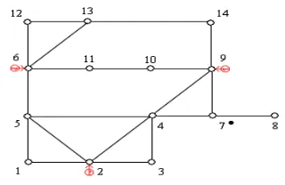
PMUs provide two types of measurements: bus voltage phasors and branch current phasors. Depending on the type of PMUs used the number of channels used for measuring voltage and current phasors will vary. In this report, it is assumed that each PMU has enough channels to record the bus voltage phasor at its associated bus and current phasors along all branches that are incident to this bus. The objective of the PMU placement problem is to render an observable system by using a minimum number of PMUs. An example of an optimally placed set of PMUs in a 14-bus system is shown below in Figure 1.
In this system, there are three PMUs placed at buses 2, 6 and 9 respectively. Bus 7 is the only zero injection bus.
Figure 1. Optimal PMU placement for a 14-bus test system
The PMU at bus 2 can not only measure the voltage phasor of bus 2, but also the current phasors of branches 2-1, 2-3, 2-4 and 2-5. Using Ohm’s law, the voltage phasors at buses 1, 3, 4 and 5 can be obtained from the branch currents and the voltage at bus 2. Having determined voltage phasors at buses 1, 2, 3, 4, and 5, the current phasors of branches 1-5, 3-4 and 4-5 can be calculated. Following the same logic, PMU at bus 6 can measure the voltage phasor at bus 6 and the current phasors of branches 6-5, 6-11, 6-12 and 6-13, thus allowing the calculation of the voltage phasors at buses 5, 11, 12, 13 and the current phasor of branch 12-13. PMU at bus 9 can measure the voltage phasor at bus 9 and the current phasors of branches 9-4, 9-7, 9-10, 9-14 and allow the calculation of the voltage phasors at buses 4, 7, 10, 14, and the current phasors of branches 4-7. As voltage phasors of buses 10, 11, 13, 14 are known, current phasors of branches 10-11 and 13-14 can now also be calculated. Using the known current phasors of branches 4-7 and 9-7, and the zero injection at bus 7, the current phasor of branch 7-8 can be derived using the Kirchhoff’s Current Law. The only remaining unknown voltage phasor at bus 8 can now be calculated by using the voltage phasor at bus 7 and the current phasor of branch 7-8. Thus the entire system becomes observable by placing only three PMUs at buses 2, 6, 9 and by considering the zero injection at bus 7.
In this artcle, a procedure based on Integer Linear Programming using MATLAB software to find out the minimum number of PMUs and their location so that the entire power system network will be observable. The procedure is explained with a IEEE 14-bus system clearly.
2.1 Integer Programming Based Procedure
IJISET - International Journal of Innovative Science, Engineering & Technology, Vol. 2 Issue 4, April 2015. www.ijiset.com
ISSN 2348 – 7968
For an n-bus system, the PMU placement problem can be formulated as follows:
min ∑ wi xi
s.t. f ( X ) ≥ 1 where
X is a binary decision variable vector, whose entries are defined as:
if a PMU is installed at bus i Xi = 1
otherwise
0
wi is the cost of the PMU installed at bus i.
f(X) is a vector function, whose entries are non-zero if the corresponding bus voltage is solvable using the given measurement set and zero otherwise.
1ˆ is a vector whose entries are all ones.Inner product of the binary decision variable vector and the cost vector represents the total installation costs of the selected PMUs. Constraint functions ensure full network observability while minimizing the total installation cost of the PMUs.
The procedure for building the constraint equations will be described for three possible cases where there are (1) no conventional measurement or zero injections, (2) flow measurements or (3) flow measurements as well as injection measurements (they may be zero injections or measured injections). Description of the procedure for each case will be given using IEEE 14-bus system example for clarification. However, the entire procedure is actually programmed and successfully tested on different size systems with diverse measurement configurations.
Consider the IEEE 14-bus system and its measurement configuration shown in Figure 2. The black dot near bus 7 represents that bus 7 is a zero injection bus (or has a injection measurement installed) while the black box on line 5-6 represents a paired flow measurement on line 5-6.
Figure 2. IEEE 14-bus system with conventional measurements
Here, we have two cases:
Case 1. A system with no conventional measurements and/or zero injections
Case 2: A system with some flow measurements
But, in this we deal only with a system considering no conventional measurements and/or zero injections
Case: A system with no conventional measurements and/or zero injections
In this case, the flow measurement and the zero injection are ignored. In order to form the constraint set, the binary connectivity matrix A, whose entries are defined below, will be formed first:
1 if k = m or k and m are connected A k,m =
0 if otherwise
Matrix A can be directly obtained from the bus admittance matrix by transforming its
The in t one For and
The mu ma f 2
i)
Fig
Th
e operator ‘+’ the right hand e of the variab r example, con d 2 as given be
f1 f2 e first constra ust be placed a ake bus 1 obs ≥ 1 indicates th
IEEE 14-bus
gure 3. IEEE 14
he Information
IJISET - Interna
serves as the l side of the in bles appearing nsider the cons elow,
1 = x1 + x2 + x5 = x1 + x2 + x3 int f1 ≥ 1 imp at either one o servable. Simi hat atleast one P
s system
IEEE 14
4-bus system
n of the IEEE
ational Journal of
logical ‘OR’ an nequality ensur
in the sum wi straints associa
≥ 1
3 + x4 + x5 ≥ 1 plies that at le
f buses 1, 2 o larly, the seco PMU should b
4-bus
E 14 system an
Innovative Scienc w
nd the use of 1 res that at least ll be non zero ated with bus 1
east one PMU or 5 in order to ond constraint be installed.
nd simulation
ce, Engineering & www.ijiset.com
1 t . 1
U o
t
n
resul
Table
ii)
Figur
The are g
Table
Sy
IE bu
3. Si
Technology, Vol.
lts are given in
e 1 System info
System
IEEE 14-bus
IEEE 30-bus
re 4. IEEE 30-b
Information given in the Ta
e 2 System info
ystem #
br
EEE
30-us 41
imulation Re
2 Issue 4, April 20
n the Table 1.
formation of IE
# of branches
20
system
bus system
of the system able 2.
formation of IE
of ranches
1
esults
015.
IS
EEE 14-bus sys
f
# of PMUs
4
m and simula
EEE 30-bus sys
# of PMUs
10
SN 2348 – 7968
stem
Location o
PMUs a
buses
2,6,7,9
ation results
stem
Location of PMUs at buses
2, 4, 6, 9, 10, 12, 15, 18, 25, 27
IE IE 4. C Pro line PM IEE com
EEE 14-bus sy
EEE 30-bus sy
CONCLUSI
ogram is devel ear integer pro MU’s and their EE 14bus ,30 mpletely observ
1. R.F. Nuq placemen observabi ,pp. 2381 2. A.G. Pha
power system,” 10- 15, A 3. T.L. Bal ,”Power
IJISET - Interna
ystem simulati
stem simulatio
ON:
loped in MAT ogramming for location consi 0 bus power
vable.
Refere
qui and A.G.Pha nt techniques f ility, ” IEEE Tr -2388, Oct. 200 adke ,”Synchron
IEEE Comput . April 1993.
ldwin ,L. Mili
ational Journal of
ion results
on results
TLAB software determining o dering 2 cases systems. Th
ences
adke ,”Phasor m for complete a rans. Power De 5.
nized phasor m
Appl. Power ,v
,M.B. Boisen
Innovative Scienc w
e using binary optimum no. of for 2 different he results are
measurement unit and incomplete el.,vol. 20 ,no. 4
measurements in
vol. 6 ,no. 2 ,pp
n ,and R.Adapa
ce, Engineering & www.ijiset.com y f t e t e 4 n . a 4 5 6 7 8 9 1 1 1 Technology, Vol. system obs placement pp. 707-715 4. T. W. Hayn Electric Pow 15,No. 4, 2 5. B. Xu an measureme proc. IEEE Expo., Oct. 6. M. Farsadi measureme with differ Electrical a 7. G. Venugo "Optimal P system usin Engineering 8. T.-T. Cai placement and Engine 38-43. 9. A. Z.Z. Ga
S. Korkina estimation, Deregulatio Technologi 10. Optimal Pl Power Syst Injection B and Ad Ho Volume‐1 11. J. Peng, Y placement for full N algorithm," Energy Sys 12. M. Hajian, "Optimal particle sw Conf. on Systems, pp
2 Issue 4, April 20
servability with ,”IEEE Trans. P 5 , May 1993. nes et al, “Dom wer Networks”, 002.
nd A. Abur, ent placement f E Power Eng. . 2004, pp. 943– i, H. Golahmad ent unit (PMU) rent algorithms and Electronics E opal, R. Veilum PMU placement ng PSAT," in 20 g and Technolog and Q. Ai, " in power System eering Academy
amm, I. N. Kolos a, PMU placem
" in 2008 Int on and Re ies,pp. 645-649. lacement of Ph tem Observabili Buses Internation
c Networks (IJS 1, Issue‐4, 2012 Y. Sun, and H
Network observ " International J stems, vol. 28, no
A. M. Ranjbar, placement of warm optimizati Intelligent Syst p. 1-6. 015. IS minimal phasor Power System ,
mination in Grap SIAM J. Discre
“Observability for systems wit
Soc. Power S 946.
di, and H. Sho allocation in p s", in 2009 In Engineering, pp. muthu, and P. A t and observabi 010 Int. Joint Jou gy, pp.67-71. "Research of P ms," in 2005 W y and Society I
sok, A. M. Glaz ment criteria f t. Conf. on El
estructuring
hasor Measurem ity Without Con nal Journal of S SSAN) ISSN No
2 122 .
H. F. Wang, "O
vability using Journal of Electr o. 4, pp. 223-23
T. Amraee, and phasor measu ion approach," tems Applicatio
SN 2348 – 7968 r measurement , vol 8 ,no. 2,
phs Applied to ete Math., Vol.
analysis and th PMUs,” in Systems Conf.
ojaei, "Phasor power system nt. Conf. on
396-400. Avila Theresa,
ility of power urnal Conf. on
PMU optimal orld Scientific Int. Conf., pp.
zunova, and E. for EPS state
lectric Utility and Power
ment Units for nsidering Zero Smart Sensors o. 2248‐9738
Optimal PMU
Tabu search rical Power & 1, May 2006.
A. R. Shirani, urement units