high-throughput AES implementations: How
fast can we go?
⋆Lejla Batina1
, Domagoj Jakobovic2
, Nele Mentens3
, Stjepan Picek1,2
, Antonio de la Piedra1
, and Dominik Sisejkovic2
1
Digital Security Group, ICIS, Radboud University Nijmegen, The Netherlands {lejla, s.picek, a.delapiedra}@cs.ru.nl
2
Faculty of Electrical Engineering and Computing, University of Zagreb, Croatia {domagoj.jakobovic, dominik.sisejkovic}@fer.hr
3
KU Leuven ESAT/COSIC and iMinds, Leuven-Heverlee, Belgium [email protected]
Abstract. In the last few years, several practitioners have proposed a wide range of approaches for reducing the implementation area of the AES in hardware. However, an area-throughput trade-off that under-mines high-speed is not realistic for real-time cryptographic applications. In this manuscript, we explore how Genetic Algorithms (GAs) can be used for pipelining the AES substitution box based on composite field arithmetic. We implemented a framework that parses and analyzes a Verilog netlist, abstracts it as a graph of interconnected cells and gener-ates circuit statistics on its elements and paths. With this information, the GA extracts the appropriate arrangement of Flip-Flops (FFs) that maximizes the throughput of the given netlist. In doing so, we show that it is possible to achieve a 50 % improvement in throughput with only an 18 % increase in area in the UMC 0.13µm low-leakage standard cell library.
Keywords: Real-time cryptography, Genetic Algorithms (GAs), S-boxes.
1
Introduction
Implementations of cryptography are of constant interest for companies making security products. The challenges vary from very compact, low-power/energy to high-speed implementations of both symmetric and asymmetric cryptographic algorithms. Ever growing applications require security services, introduce more constraints and real-time crypto has become of paramount importance.
This race for the fastest implementations in both hardware and software is especially difficult for algorithms that feature endless implementation options
such as Elliptic Curve Cryptography (ECC) and the AES standard. For example AES can be implemented with table look-ups or via multiple composite field representations, each of which has certain advantages for area, performance and security [1–4]. Moreover, other practitioners have relied on resource sharing and folded architectures for reducing the implementation area [5, 6]. However, when considering fast hardware implementations, pipelining is an obvious choice to increase the throughput. Nevertheless, as pipelining implies adding FFs, it also increases the area.
An interesting research challenge is to optimize throughput, while keeping the area under control. More precisely, considering compact options for the AES S-box, namely those relying on composite field arithmetic, which are the best pipelining solutions to maximize the throughput? Strategies for solving this prob-lem typically involve hardware tools and rely mostly on good hardware design practice, but are generally far from straightforward. The goal of this research is to investigate this problem of optimizing the performance via pipelining such that the best throughput is found for a given composite field S-box. For this purpose we use genetic algorithms that have already found their place in other cryptographic applications.
Our contribution is in comprehensively evaluating how to boost the perfor-mance of AES implementations based on composite field arithmetic. To this end, we consider a hardware implementation where the S-box is implemented using
a polynomial basis inGF(((22
)2
)2
) as used for example by Satohet al. [2] and
Mentenset al.[3]. We deploy genetic algorithms to find a good solution for the
position of the pipelining FFs in order to reduce the critical path as much as possible.
Through our methodology we find a solution that adds one level of pipelining registers in order to increase the throughput of the S-box with 50 % while the extra FFs only increase the area with 18 %. To underline the added value of our approach, we add some statistics on the circuit under investigation, which show that it is far from straightforward to find this solution.
The remainder of this paper is organized as follows. First, in Section 2, we describe how GAs have been coupled with cryptographic applications in the literature as well as different alternatives for exploring the design space of an AES implementation. In Section 3 we illustrate the initial design of the AES S-box based on composite fields that we have selected for this work. Then, in Section 4, we present the framework that we have developed for analyzing Verilog netlists, generating an appropriate input for the GA, evaluating the correctness of the resulting netlist and synthesizing our solution. In Section 5, we describe our results and end in Section 6 with some conclusions.
2
Related Work
a design choice that is similar to ours. The main focus is on implementations using composite field arithmetic to boost compactness and/or speed.
Satohet al. were the first to introduce a new composite fieldGF(((22
)2)2 )-based implementation which resulted in the most compact S-box at the time
with a gate complexity of 5.4 kgates. Wolkerstorferet al. [7] used arithmetic in
GF((24
)2) to achieve an implementation with a gate count comparable to the
one presented by Satoh et al.(5.7 kgates). Mentens et al.[3] and Canright [4]
found the best choice of polynomials and representation to optimize the S-box
area for polynomial and normal basis respectively. However, Moradiet al.have
recently published the most compact AES implementation [8] of the size of only 2.4 kgates. This result is obtained by optimizing AES encryption on all layers
and pushing the area to this minimum. Hodjatet al.[9] have described an ASIC
implementation for the same composite fieldGF((24
)2) as Wolkerstorfer. Their approach was to perform an area-throughput trade-off by fully pipelining the architecture and optimizing the key-schedule implementation. One of the more
recent works is from Kumaret al.[10] considering an FPGA implementation of
AES based on inversion inGF(28
). The critical path they obtain is 4.6 ns, which is substantially slower than our best result (2.6 ns). In general, hardware design tools consist of algorithms that focus on the optimization of area, speed and/or power/energy consumption, but none of the tools handles automatic pipelining to the extend that we do in this paper.
The literature is rich in examples where researchers have been relying on GAs
for solving cryptographic problems. For instance, Jhajharia et al. and Sokouti
et al.proposed the utilization of GAs for generating cryptographic keys [11, 12].
Further, Zarzaet al.and Parket al.utilized GAs in the context of cryptographic
protocol design [13, 14]. Carpiet al.studied the selection of security parameters
for protecting smart cards against fault attacks via GAs [15]. Moreover, there are many successful applications of evolutionary computation when evolving
S-boxes. Clarket al. used the principles from the evolutionary design of Boolean
functions to evolve S-boxes with desired cryptographic properties [16]. They used the Simulated Annealing (SA) heuristic coupled with the hill-climbing algorithm
to evolve bijective S-boxes with high non-linearity. Picek et al. used genetic
algorithms to evolve S-boxes of various sizes that have better resistance to DPA attacks [17, 18].
In this work, we use GAs to explore the design space of a standard cell netlist that has many unbalanced and partially overlapping paths from input to output. In order to achieve high throughput, GAs are used to choose the position of the pipelining FFs. We are not aware of prior work addressing pipelining of digital circuits using evolutionary computation.
3
S-box Implementation
and Mentens et al.[3] that the most compact solutions rely on composite field arithmetic.
Considering various arithmetic options in binary extension fields to optimize the inversion operation in the AES S-box, there are basically two implementation
options. We can either perform the subfield operations directly inGF(24
) or we
can perform computations in the tower field GF(((22
)2)2), i.e. working in all subfields and using the fact that inversion is linear inGF(22
). The latter option is the one we choose.
The fieldGF(((22
)2)
2
) is considered as an extension of degree 2 overGF((22
)2)
constructed using the irreducible polynomial P(x) = x2
+p1x+p0, where
p1, p0∈GF((22) 2
).GF((22
)2) is a field extension of degree 2 overGF(22
) using the irreducible polynomialQ(y) =y2
+q1y+q0 with q1, q0 ∈GF(22). GF(22)
is a field extension of degree 2 over GF(2) using the irreducible polynomial
R(z) =z2
+z+ 1. The constants are given in Appendix A.
In this case, inversion inGF(22
) requires only one addition:
d=t1z+t0∈GF(2 2
) :d−1=t1z+ (t1+t0). (1)
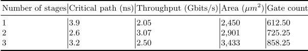
These operations are implemented as depicted in Fig. 1.
Unlike the inversion inGF((24
)2), the building blocks are not implemented
as 4-bit look-up tables, but as operations inGF((22
)2), which can be computed
as follows (witha1, a0, b1, b0∈GF(22)):
– (a1y+a0)·(b1y+b0) = (a1b1+a1b0+a0b1)y+ (a1b1φ+a0b0);
– (a1y+a0)2=a1y+ (a1φ+a0);
– (a1y+a0)·λ= (a1y+a0)ωy= (a1+a0)ωy+a1ωφ.
These equations consist of operations in GF(22
) that can be computed as follows (withg1, g0, h1, h0∈GF(2)):
– (g1z+g0)·(h1z+h0) = (g1h1+g0h1+g1h0)z+ (g1h1+g0h0);
– (g1z+g0) 2
=a1z+ (a1+a0);
– (g1z+g0)·φ= (g1z+g0)·z= (g1+g0)z+g1;
– (g1z+g0)·ω = (g1z+g0)·(z+ 1) =g0z+ (g1+g0).
4
Methodology
In this section we provide an explanation of the framework that we have devel-oped for interfacing the GA with different modules for analyzing, simulating and synthesizing evolved netlists (Figure 2). First, we parse a Verilog description of a certain circuit, which is, in our case, the S-box design described in Section 3.
8 4
4
4
4 8
*
λ
^2
^−1
Fig. 1.Schematic of the S-box by Satohet al.[2], where the building blocks are oper-ations inGF((22
)2), which are decomposed into operations inGF(22 ).
.v
netlist 1. Analysis
2. Genetic
Algorithm
"000110001010..." 3. Netlist
Simulation OK? No
Yes
4. Simulation
5. Synthesis regeneration
Fig. 2.Workflow of our approach for pipelining the AES S-box
of FFs that maximizes the throughput of the substitution box. The FFs are inserted in a new netlist, simulated and synthesized (Steps 3–5 in Figure 2). In the following sections, we first describe our optimization problem and then we continue on each step and relate our results using the design described in Section 3.
4.1 Pipelining as an Optimization Problem
The task at hand is to insert a combination of FFs in order to increase throughput through a certain number of pipeline stages. A valid solution to this problem requires that all the paths in the circuit contain the same number of FFs, which are placed in a way that minimizes the delay in each pipeline stage. For a given number of stages, the number of FFs at every path is one less than the number of stages (i.e. one FF per path in a two-stage pipeline).
for all circuit elements. In this encoding, a bit is set to the value “0” if the corresponding input does not have an associated FF and to the value “1” if there is a FF preceding that input (the unmodified circuit is represented with all zeros). The total bitstring length is equal to the sum of all the inputs in the circuit, which in this case amounts to 432. A potential solution is therefore a
sequence of bits of length 432, which defines a search space of 2432
.
The quality (also called the fitness value) of each potential solution is de-termined by the delay of the pipeline stage with the greatest delay among all the stages. However, since the optimization algorithm operates with any com-bination of bits in the search process, a great number of potential solutions are expected to be infeasible, because they will represent a circuit with a different number of FFs in all the paths. To handle that constraint, a penalty factor can be included in the quality estimate to differentiate between feasible and infeasible solutions. The penalty should be great enough such that each feasible solution (a circuit with the same number of FFs in every path), regardless of the delay, is still better than any infeasible solution, to guide the search to valid solutions. Based on the previous, we define the following fitness function that represents the optimization problem:
f itness=max delay time+ (1,000∗number invalid paths) (2)
Here,max delay timepresents the longest delay for every pipeline stage and
invalid paths are all those that do not have a correct number of FFs. We ex-perimentally set the weight to be 1,000 in the formula above. Intuitively, the weight needs to be large enough such that even in the case that there is only one invalid path, the total fitness should be worse than for the solution without FFs. For that same reason, every larger weight factor would work the same. The optimization objective is the minimization of the fitness function. Note that to calculate the maximum delay, all possible paths in the network need to be traversed, which poses a fairly large computational demand.
In the next section we describe the first step in Figure 2, focused on the analysis of netlists.
4.2 Analysis of Verilog Netlists
Our framework generates statistical information about a circuit represented as a Verilog netlist. In Table 1 we show the statistical details related to our choice of representation. These parameters are extracted using the framework we de-veloped for pipelining the AES substitution box. The number of elements in the table denotes the number of standard cells. The number of inputs refers to the number of inputs to all standard cells. Finally, the number of paths denotes the number of different possible paths through the circuit from an input to an output.
Table 1.Statistics of the preliminary S-box design
Number of elements Number of inputs Number of paths Shortest path Critical path (ps)
165 432 8,023,409 4 3,884.52
is relatively small, we decided to encode the possible solutions as bitstrings where each bit represents every input location for all elements.
Given a netlist of the S-box in Verilog, our framework first parses it according
to a predefined grammar and then, each element from the UMC 0.13 µm low
leakage standard cell library is identified [19]. This is done using a framework
developed inpython 2.7.5-5in combination with thepyparsing 2.0.1library
1
.
Relying on that library, we have defined a grammar that deconstructs each entry of a Verilog netlist into a set of cells and their connections. For instance, a NAND gate defined in the standard cell library can appear in a given netlist as “ND2CLD U181 ( .I1(\input [0]), .I2(\input [1]), .O(n1) );”. Hence,
the parser must identify that element as a NAND gate (ND2CLD) associated to
theU181identifier. Moreover, it must detect that is connected to the first two
inputs of the S-box and that then1wire routes its output.
This process is performed by creating a grammar that expects a set of entries consisting of:
– The type of the cell. – The cell identifier.
– A comma-separated list of inputs and outputs (i.e. I1, I2 and O in the
example) connected to the circuit inputs, outputs or internal Verilog wires
(i.e.\input [0], \input [1], andn1).
Each element of the netlist is abstracted in a data structure that stores the cell type, the cell identifier, the number of inputs of the cell and all the elements that are connected to their inputs i.e. their adjacent elements. Moreover, the delay associated to each element according to the standard cell library is also stored. This information is later used as an input for the optimization algorithm. The resulting list contains all the circuit cells together with their number of inputs and their adjacent nodes (that is, the cells that are connected to their inputs) as well as the delay of each element. A small example of the parser output is given below:
U163 2 U251 U248 146.8
U164 3 U198 U256 U163 86.471
U165 4 U198 U163 U256 U164 98.369
U166 1 U207 59.39
U167 4 U207 U209 U210 U166 114.406
1
This example describes the number of inputs for the cellsU163-U167(i.e. 2, 3, 4, 1, 4 respectively) together with the cells that are connected to those inputs and the respective delay of the cell according to the standard cell library.
These values are obtained as average values for all possible combinations (transitions from low to high and from high to low) for each element. For each FF element that will be inserted in order to maximize the throughput, we use a
D-FF with a single output and no clear, set or enable (QDFFCLD) with an average
delay time of 320.35 ps. All delay times are given for a temperature of 25 degrees Celsius, a core voltage of 1.2 V and a load capacitance of 1.5 fF.
Taking the average of low-to-high and high-to-low delays and assuming a low load capacitance of 1.5 fF is an approximation that gives good results. Never-theless, to improve our methodology, the actual delay information based on the load of each standard cell should be taken into account.
Next, we present the optimization algorithm we used to generate pipelined circuits.
4.3 Genetic Algorithms
In accordance with the given representation, we selected genetic algorithms (GAs) as the optimization method to be used in our experiments.
Prior to going into to the details about genetic algorithms, first we offer a short rationale behind the choice of them. Since there is no previous work that uses any kind of heuristics to evolve the optimal arrangement of FF elements in a combinatorial circuit, we believe we should start with some well-researched algorithm that can be easily adapted.
Genetic algorithms are an evolutionary computation technique that has been successfully applied to various optimization problems. Additionally, bitstring representation is one of several standard representations of GAs [20]. Naturally, there are other heuristic algorithms that also use bitstring representation (e.g. Particle Swarm Optimization [21], Genetic Annealing [22]) that could be used here. In accordance with that, it is not possible to stipulate what algorithm would perform the best. The “No Free Lunch” theorem states that there is no single best algorithm for all the problems, i.e. when averaged over all search problems, all algorithms behave the same [23]. Therefore, only thorough experimental work can give insight into more appropriate algorithms. Further details about genetic algorithms and operators we use are given in Appendix B.
Common Parameters. The parameters used in each run of the algorithm are the following: the number of independent runs for each evolutionary experiment
is 30 and the population size is 30. The tournament size k in the tournament
selection is equal to 3. Mutation probability is set to 0.45 per individual where we choose it on a basis of a small set of tuning experiments where it showed the best results on average.
levels of FF elements we want in our circuit. From Table 1 we see that the number of elements in the shortest path is 4. Therefore, this path can have only 3 levels of FFs and that is the maximum number of FFs our circuit can have in order to produce a correct output.
Evolutionary Process. After the parameters are set, the GA starts with the generation of the initial population. In this part, the genetic algorithm reads all the elements of the parser output file and for each cell input it reserves one position in the bitstring representation. Notice that our bitstring size is fixed for a given circuit and it can not be dynamically changed during the evolutionary process. This results in the fact that our current setting does not support multiple FF elements one after the other. The initial population is built by creating random bitstrings of the designated length corresponding to randomly setting FFs in the preliminary netlist.
When the initial population is generated, the genetic algorithm starts with
the evolution process. In each iteration it randomly chooseskpossible solutions
(the k tournament size) and eliminates the worst solution among those (this
is also to ensure elitism i.e. the best solutions are always propagated to the next generation). The remaining solutions are used as parents which create one offspring via variation operators. The offspring (new solution) then replaces the worst individual in the population and additionally undergoes a mutation with a given probability.
For each offspring, a genetic operator is selected uniformly at random between all operators within an operator class (mutation or crossover). We use simple and mix mutations and uniform [24] and one-point [20,25] crossover operators. These variation operators are selected among those that are commonly used nowadays. The evolution process repeats until the stopping criterion is met. In our case, the stopping criterion is based on 50 generations without improvement of the best solution.
4.4 Reconstructing Evolved Individuals to the Netlist
Using a list of structures described in Section 4.2 it is possible to compute all the paths of the circuit based on all the possible combinations for the eight inputs and outputs of the AES substitution box. This is done by transforming the list of cell structures described above into a non-directed graph, where the cells are represented by nodes and their connections by edges. Then, it is possible to extract the connections in the circuit and identify all the paths for all the input-output combinations using a graph exploration algorithm such as the breadth-first search (cf. [26]). We have depicted in Figure 3 how our framework abstracts a Verilog netlist.
216 217 214 215 212 213 210 211 218 219 164 165 166 167 289 288 281 280 283 282 285 284 287 286 263 262 261 260 267 266 265 264 269 268 298 299 296 297 294 295 292 293 290 291 319 318 199 198 195 312 197 310 317 316 315 192 270 271 272 273 274 275 276 277 278 279 175 251 173 172 254 170 308 309 300 301 302 303 304 305 306 307 245 244 247 246 241 240 243 242 249 248 252 258 259 179 178 177 176 250 174 256 257 171 255 183 253 182 313 180 181 186 187 184 194 188 189 311 196 191 185 190 168 193 229 228 227 226 225 224 223 222 221 163 220 314 238 239 234 235 236 237 230 231 232 233 322 323 320 321 326 327 324 325 328 201 200 203 202 205 204 207 206 209 208 169
Fig. 3.Graph representation of the S-box connections for each cell identifier
in Figure 2). Our framework first splits the binary string from the GA in different chunks according to the number of inputs of each element. Then, it associates the respective FFs to each cell input. Moreover, the required Verilog wires that connect each FF to the input/output of the cell are added. For instance, for an
XOR gate with two inputs (e.g.XOR2ELD) and an output “11” from the GA, this
element would be reconstructed with two FFs attached to their inputs using two
wires (e.g.ff 9 q, ff 10 q) as:
QDFFCLD FF9 ( .CK(clk), .D(n180), .Q(ff_9_q) ); QDFFCLD FF10 ( .CK(clk), .D(n198), .Q(ff_10_q) ); XOR2ELD U212 ( .I1(ff_9_q), .I2(ff_10_q), .O(n201) );
Finally, a test bench with assertions for all the 256 possibilities of the S-box is created for the regenerated netlist. This is used in Mentor Graphics ModelSim 6.5c to guarantee the correctness of the new circuit. The resulting circuit is then synthesized using Synopsys Design Compiler in order to get pre-layout implementation results for the critical path delay and the area.
5
Results
5.1 Analysis framework
In our S-box design, based on 165 cells (Table 1), we required 0.465 seconds for generating the input for the GA using the described framework in a Intel Core i5-3230M CPU clocked at 2.60GHz (Step 1, Figure 2). The evaluation of one generation consisting of 100 individuals requires 3.5 min. on average (Step 2, Figure 2). All the experiments carried out with GAs were conducted in an Intel i5-3470 CPU equipped with 6 GB of RAM.
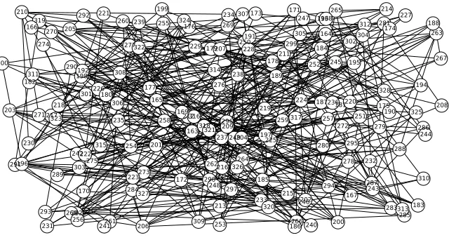
In Table 2 we give an overview of the total number of paths sorted into classes according to the maximum delay time. Each initial circuit represents a certain solution without FFs whereas the evolved circuit is the solution with the maximum delay time (2,793.62 as given in Table 3 for the best solution we found). Additionally, in Table 3 we present different statistics for several evolved circuits. Here, column Number of FFs represents the total number of flip-flops in evolved circuit and column Number of generations represents how long was GA running.
Table 2.Number of paths per length class
Class Initial circuit Evolved circuit
0 – 500 2 5,570
500 – 1,000 2,164 78,5432 1,000 – 1,500 149,944 3,751.897 1,500 – 2,000 2,026.442 2,639.751 2,000 – 2,500 3,580,150 816,636 2,500 – 3,000 1,899,675 26,411 3,000 – 3,500 361,708 0 3,500 – 4,000 3,324 0
Table 3.Statistics of evolved circuits
Max. delay time (ps) Number of stages Number of FFs Number of generations
2,793.62 2 73 587
2,826.52 2 68 15
2,942.42 2 66 691
3,155.11 2 49 482
3,223.02 2 64 4452
3,247.64 2 42 1434
2,918.92 3 100 618
5.2 Synthesis
critical path of 2,793.62 ns. The best solution with two layers of pipelining FFs to have the shortest critical path is 2,918.92 ns. Intuitively, we would expect the solution with two layers of pipelining to have the shortest critical path. However, because the number of possible solutions is much bigger for a 3-stage circuit than for a 2-stage circuit, the optimal solution found by the GA for the 3-stage circuit is worse than the optimal solution it finds for the 2-stage circuit. Nevertheless, we know that there should exist a better solution for 3 than for 2 when a longer search is performed.
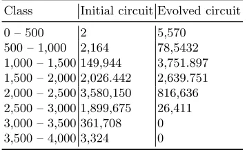
We synthesized both solutions, resulting in Table 4. In order to evaluate the critical path properly, we inserted flip-flops at the inputs and outputs of all the S-boxes. As mentioned before, the implementation corresponds to the state-of-the-art design of Mentens et al. described in [3]. The netlist with 1 stage only contains these input and output flip-flops. The netlists with 2 and 3 stages contains 1 and 2 layers of pipelining flip-flops, respectively. Because of these input and output flip-flops, the netlist with only one stage is larger in area than the composite field S-boxes reported in literature (they do not contain any flip-flops). The table shows that the 2-stage S-box introduces a 50 % improvement in throughput, which is equal to the number of bits at the output (8 in our case) divided by the delay of the critical path. The increase in area is only 18 %. The synthesis results for the critical path are even slightly better than the estimate of the GA. The reason is that the synthesis tool optimizes the generated pipelined netlist again, which leads to further improvements. For the 3-stage S-box, the synthesis results are worse than the estimate of the GA. This is probably due to the fact that there is less room for optimization with two layers of pipelining flip-flops and thus less logic in between the layers.
Table 4.Pre-layout synthesis results of the netlist with 1, 2 and 3 stages.
Number of stages Critical path (ns) Throughput (Gbits/s) Area (µm2
) Gate count
1 3.9 2.05 2,450 612.50
2 2.6 3.07 2,901 725.25
3 3.2 2.50 3,433 858.25
6
Conclusion
This paper presents a methodology for pipelining composite field AES S-boxes to maximize the throughput using genetic algorithms. The best trade-off between throughput and area results in a throughput of 3.07 Gbits/s and an area of 2,901
µm2
in a UMC 0.13µmstandard cell library. This comes down to a throughput
References
1. Fischer, V., Drutarovsk´y, M.: Two Methods of Rijndael Implementation in Re-configurable Hardware. In C¸ etin Kaya Ko¸c, Naccache, D., Paar, C., eds.: CHES. Volume 2162 of Lecture Notes in Computer Science., Springer (2001) 77–92 2. Satoh, A., Morioka, S., Takano, K., Munetoh, S.: A compact rijndael hardware
architecture with s-box optimization. In Boyd, C., ed.: ASIACRYPT. Volume 2248 of Lecture Notes in Computer Science., Springer (2001) 239–254
3. Mentens, N., Batina, L., Preneel, B., Verbauwhede, I.: A systematic evaluation of compact hardware implementations for the Rijndael S-BOX. In: Proceedings of the 2005 international conference on Topics in Cryptology. CT-RSA’05, Berlin, Heidelberg, Springer-Verlag (2005) 323–333
4. Canright, D.: A very compact s-box for aes. In Rao, J.R., Sunar, B., eds.: CHES. Volume 3659 of Lecture Notes in Computer Science., Springer (2005) 441–455 5. Fischer, V., Drutarovsk´y, M., Chodowiec, P., Gramain, F.: InvMixColumn
decom-position and multilevel resource sharing in AES implementations. IEEE Trans. VLSI Syst.13(8) (2005) 989–992
6. Chodowiec, P., Gaj, K.: Very Compact FPGA Implementation of the AES Algo-rithm. In: CHES. (2003) 319–333
7. Wolkerstorfer, J., Oswald, E., Lamberger, M.: An ASIC implementation of the AES sboxes. In Preneel, B., ed.: Topics in Cryptology - CT-RSA 2002, The Cryp-tographer’s Track at the RSA Conference, 2002, San Jose, CA, USA, February 18-22, 2002, Proceedings. Volume 2271 of Lecture Notes in Computer Science., Springer (2002) 67–78
8. Moradi, A., Poschmann, A., Ling, S., Paar, C., Wang, H.: Pushing the Limits: A Very Compact and a Threshold Implementation of AES. In: EUROCRYPT. (2011) 69–88
9. Hodjat, A., Verbauwhede, I.: Area-throughput trade-offs for fully pipelined 30 to 70 gbits/s AES processors. IEEE Trans. Computers55(4) (2006) 366–372 10. Kumar, S., Sharma, V., Mahapatra, K.: Low latency VLSI architecture of S-box
for AES encryption. In: Circuits, Power and Computing Technologies (ICCPCT), 2013 International Conference on. (March 2013) 694–698
11. Jhajharia, S., Mishra, S., Bali, S.: Public key cryptography using neural networks and genetic algorithms. In Parashar, M., Zomaya, A.Y., Chen, J., Cao, J., Bouvry, P., Prasad, S.K., eds.: IC3, IEEE (2013) 137–142
12. Sokouti, M., Sokouti, B., Pashazadeh, S., Feizi-Derakhshi, M.R., Haghipour, S.: Genetic-based random key generator (GRKG): a new method for generating more-random keys for one-time pad cryptosystem. Neural Computing and Applications 22(7-8) (2013) 1667–1675
13. Zarza, L., Pegueroles, J., Soriano, M., Mart´ınez, R.: Design of cryptographic proto-cols by means of genetic algorithms techniques. In Malek, M., Fern´andez-Medina, E., Hernando, J., eds.: SECRYPT, INSTICC Press (2006) 316–319
14. Park, K., Hong, C.: Cryptographic protocol design concept with genetic algorithms. In Khosla, R., Howlett, R.J., Jain, L.C., eds.: KES (2). Volume 3682 of Lecture Notes in Computer Science., Springer (2005) 483–489
15. Carpi, R.B., Picek, S., Batina, L., Menarini, F., Jakobovic, D., Golub, M.: Glitch it if you can: Novel parameter search strategies for successful fault injection. In: CARDIS. (2013)
17. Picek, S., Ege, B., Batina, L., Jakobovic, D., Chmielewski, L., Golub, M.: On Using Genetic Algorithms for Intrinsic Side-channel Resistance: The Case of AES S-box. In: Proceedings of the First Workshop on Cryptography and Security in Computing Systems. CS2 ’14, New York, NY, USA, ACM (2014) 13–18
18. Picek, S., Ege, B., Papagiannopoulos, K., Batina, L., Jakobovic, D.: Optimality and beyond: The case of 4x4 s-boxes. In: 2014 IEEE International Symposium on Hardware-Oriented Security and Trust, HOST 2014, Arlington, VA, USA, May 6-7, 2014. (2014) 80–83
19. Faraday: Faraday Cell Library 0.13µm Standard Cell. (2004)
20. Holland, J.H. In: Adaptation in Natural and Artificial Systems: An Introductory Analysis with Applications to Biology, Control, and Artificial Intelligence. The MIT Press, Cambridge, USA (1992)
21. Kennedy, J., Eberhart, R.: Particle swarm optimization. In: Neural Networks, 1995. Proceedings., IEEE International Conference on. Volume 4. (Nov 1995) 1942–1948 vol.4
22. Yao, X.: Optimization by genetic annealing. In: Proc. of 2nd Australian Conf. on Neural Networks. (1991) 94–97
23. Wolpert, D.H., Macready, W.G.: No Free Lunch Theorems for Optimization. IEEE Transactions on Evolutionary Computation1(1) (April 1997) 67–82
24. Syswerda, G.: Uniform crossover in genetic algorithms. In: Proceedings of the 3rd International Conference on Genetic Algorithms, San Francisco, CA, USA, Morgan Kaufmann Publishers Inc. (1989) 2–9
25. Eiben, A.E., Smith, J.E. In: Introduction to Evolutionary Computing. Springer-Verlag, Berlin Heidelberg New York, USA (2003)
26. Knuth, D.E.: The Art of Computer Programming, Volume 1 (3rd Ed.): Funda-mental Algorithms. Addison Wesley Longman Publishing Co., Inc., Redwood City, CA, USA (1997)
27. Weise, T. In: Global Optimization Algorithms Theory and Application. (2009) 28. Michalewicz, Z.: Genetic algorithms + data structures = evolution programs (3rd
ed.). Springer-Verlag, London, UK, UK (1996)
Appendix A
Here we give the details of the constants used for our composite field implemen-tations of the AES S-box.
In [2], Satoh et al. made the following choices for the coefficients of the
irreducible polynomials:
p1= 1 ={0001}2,
p0=λ=ωy= (z+ 1)y={1100}2,
q1= 1 ={01}2,
q0=φ=z={10}2.
The inverse operation is implemented as
∆=δ1x+δ0∈GF(((2 2
)2)
2
) :
∆−1= (δ
1x+ (δ1+δ0))·(λδ 2
1+ (δ1+δ0)δ0)− 1
, (3)
δ=d1y+d0∈GF((2 2
)2) :
δ−1= (d
1y+ (d1+d0))·(φd 2
1+ (d1+d0)d0)− 1
Inversion inGF(22
) requires only one addition:
d=t1z+t0∈GF(2 2
) :d−1=t
1z+ (t1+t0). (4)
Appendix B
Genetic algorithms belong to the evolutionary family of algorithms where the
elements of the search space S are arrays of elementary type [27]. We give a
short pseudo-code for a genetic algorithm (this is also a pseudo-code for any evolutionary algorithm) in Algorithm 1.
Algorithm 1Genetic algorithm
Input: P arameters of the algorithm Output: Optimal solution set t←0
P(0)←CreateInitialP opulation whileT erminationCriteriondo
t←t+ 1
P′(t)←SelectM echanism(P(t−1)) P(t)←V ariationOperators(P′(t)) end while
Return OptimalSet(P)
In order to produce new individuals (solutions), the GA uses mutation and crossover operators. Mutation operators use one parent to create one child by applying randomized changes to the parent. The mutation depends on the
mu-tation ratepmwhich determines the probability that a change will occur within
an individual. Crossover operators modify two or more parents in order to create an offspring via the information contained within parent solutions. Recombina-tion is usually applied probabilistically according to a crossover ratepc. In this
work, we use only operators that work with two parents. Additionally, GAs use selection methods to choose the individuals that will continue to the next gener-ation. We opted here for the steady-state tournament or k-tournament selection
method [27]. In this selection from k randomly selected individuals, two with
the best fitness values are chosen to evolve and create one offspring, replacing the worst from the tournament [25, 28].
Next, we give a short description of crossover and mutation operators that we use.
Uniform Crossover. Single and multi-point crossover defines cross points as places between positions where an individual can be split. Uniform crossover gen-eralizes this scheme to make every place a potential crossover point. A crossover mask, the same length as the individual structure is created at random and the parity of the bits in the mask indicate which parent will supply the offspring with which bits. The number of effective crossing points in uniform crossover is
not fixed, but will average to l/2 wherel represents string length.
Mix Mutation. Mix (or mixing) mutation randomly chooses one area inside the individual where it will change the bits. First, in that area number of ones and zeros is counted and then random bits are set while preserving the respective number of values [20].
Simple Mutation. In simple mutation every bit is inverted with a predefined
![Fig. 1. Schematic of the S-box by Satohations in et al. [2], where the building blocks are oper- GF((22)2), which are decomposed into operations in GF(22).](https://thumb-us.123doks.com/thumbv2/123dok_us/7907421.1312979/5.595.199.416.258.434/fig-schematic-satohations-building-blocks-oper-decomposed-operations.webp)