A Novel Range Compression Algorithm for
The Resolution Enhancement in GNSS-SAR
Yu Zheng *, Yang Yang and Wu Chen
Department of Land Surveying and Geo-informatics, The Hong Kong Polytechnic University, Hong Kong, China; [email protected] (Y.Y.); [email protected] (W.C.)
* Correspondence: [email protected]; Tel.: +852-5309-1110
Abstract: Passive Global Navigation Satellite System (GNSS)-based Synthetic Aperture Radar (SAR), known as GNSS-SAR, is a new passive radar imaging system. However, compared with conventional SAR, range resolution of GNSS-SAR is significantly lower. To improve range resolution of GNSS-SAR is an interested topic for investigation. In this paper, a novel range compression algorithm for enhancing range resolutions of GNSS-SAR is proposed. In the proposed scheme, at first, range compression is conducted by correlating the received reflected GNSS signal of intermediate frequency (IF) with the synchronized direct baseband GNSS signal in range domain. Then spectrum equalization is applied to the compressed results to suppress side lobes. Both theoretical analysis and simulation results have demonstrated that significant range resolution improvement in GNSS-SAR can be obtained by the proposed range compression algorithm, compared to the conventional range compression algorithm.
Keywords: GNSS-SAR; global navigation satellite system; synthetic aperture radar; range compression; range resolution
1. Introduction
Passive GNSS (Global Navigation Satellite System)-based SAR (Synthetic Aperture Radar), known as GNSS-SAR, is a developing synthetic aperture radar (SAR) technique for remote sensing in recent years [1,2]. Unlike conventional SAR techniques, GNSS-SAR is a passive SAR receiver which uses the signals from Global Navigation Satellite System (GNSS) such as GPS, Galileo, GLONASS or Beidou as transmission of opportunity. Due to the fact that there is no need to construct SAR transmitter, GNSS-SAR has a higher flexibility together with lower expenses than conventional SAR under various applications. However low range resolution is one of the main problems that affects the current development of GNSS-SAR [1,2,13,14,16].
However, a shortcoming of the approaches [13,14,16] is that multi-statistic image processing method is time consuming as they are applied after generating multiple full GNSS-SAR images.
The main contribution in this paper is to propose a new range compression algorithm for GNSS-SAR signal processing to improve range compressed resolution. In the proposed algorithm, the received intermediate frequency (IF) reflected GNSS signal is correlated with the synchronized direct baseband GNSS signal at range domain for each azimuth bin for range compression. Then spectrum equalization [11] is applied to suppress side lobes of the compressed result to enhance range resolution.
The rest of the paper is organized as follows. Resolution of the conventional range compression algorithm is analyzed in section 2. Resolution of the proposed range compression algorithm is analyzed in section3. The simulation tests are provided in section4. Section5discusses the future development of this research and Section6provides conclusions of the paper.
2. Resolution of The Conventional Range Compression Algorithm
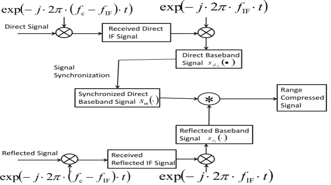
Based on the analysis in [1–4,9–12,14,16], the overall view of the conventional range compression algorithm at GNSS-SAR receiver can be illustrated as Figure1.
Direct Signal
j2 fc fIF t
exp
Received Direct IF Signal
j
2
f
IF
t
exp
Direct Baseband Signal
Range Signal
Synchronization
Synchronized Direct
2
d s
Reflected Signal
j2 fc fIF t
exp
Received Reflected IF Signal
j
2
f
IF
t
exp
Reflected Baseband Signal
Range Compressed Signal Synchronized Direct
Baseband Signal sm
*
2
r s
Figure 1.The conventional range compression algorithm.
In Figure 1, under the conventional range compression algorithm, both direct and reflected signals are quadrature converted to IF (Intermediate Frequency) band by multiplying the component exp(−j2π·(fc−fIF)·t) at first, where fc denotes the transmission frequency, fIF denotes the
intermediate frequency (IF) of the employed GNSS receiver, N
denotes the multiplication and~ denotes the correlation.
The received IF signals (both direct and reflected signal) are further down converted to baseband by multiplying the component exp(−j2π·fIF·t). The down converted baseband direct signal can
then be expressed as
sd2(t,u) =Ad(t,u)C[t−τ(u)]D[t−τ(u)]
×exp(j(2πfd·t+φd(u)))
+nd(t,u)
and reflected baseband signal can be expressed as
sr2(t,u) =Ar(t,u)C[t−τ(u)−τR(u)]
×D[t−τ(u)−τR(u)]
×exp(j(2πfd·t+φr(u)))
+nr(t,u).
(2)
where Adand Ar denotes magnitudes of the direct and reflected signals respectively; C(·)denotes PRN code; D(·) denotes the navigation bits; t denotes the range domain; u denotes the azimuth domain;τdenotes the received direct signal delay relative to the transmitted signal;τRdenotes the received reflected signal delay relative to the direct signal; fddenotes Doppler frequency;φddenotes direct signal phase, andφr denotes reflected signal phase, which can be regarded as constant values within each range domain; j denotes the symbol of complex number; nd denotes the background noise at direct channel andnrdenotes the background noise at reflected channel.
Thereafter signal synchronization based on received direct IF signal as (1) is performed, and the synchronized direct baseband signal is severed as imaging matched filter, which can be modeled as follows
sm(t,u) =C[t−τ(u)]D[t−τ(u)]×exp(j2πfd·t). (3) Range compression is conducted through correlating baseband reflected signalsr2with imaging matched filter sm at range domain, which result with respect to the noise absence term can be expressed as follows.
sr2~s ∗ m
=Ar·Λ(t−τ(u)−τR(u))×exp(jφr(u)) (4)
where Λ(·) indicates triangle function and its duration is determined by PRN code chip rate of GNSS signal;∗denotes the conjugate. In (4), becausesr2 andsmare with the same frequency fd, the frequency component after performing range correlation for the compression is canceled. Assuming the chip rate of PRN code C(·) isB, then the half pulse duration of the triangle functionΛ(·)is derived as 21B. Because the termsAr and exp(jφr(u))are constants with respect tot, the duration of (4) will be determined by the termΛ(·). Thus the attainable range resolution with respect to pulse duration can be expressed as [1–4,6–11,14,17]
δR1 =
c
2·cos(β/2)·B (5)
wherecdenotes transmission velocity of GNSS signal,βrepresents bi-static angle andδR1 represents the achievable range resolution by the conventional algorithm. According to (5), it can be seen that for the conventional range compression algorithm in GNSS-SAR, if bi-static angleβis fixed, the range resolution improvement can only be accomplished by employing GNSS signals with a higher PRN code chip rateC(·).
3. Resolution of The Proposed Range Compression Algorithm
However according to [21], we can derive that for quadrature modulated signals of exp(j(·))
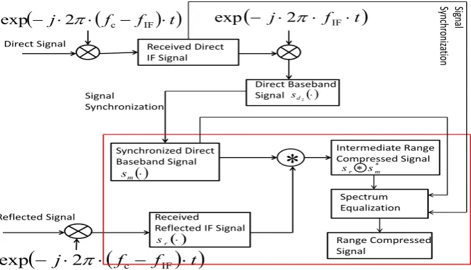
shape, if the two signals for performing correlation have the same basedband components shaped as rectangular function but different frequencies, compared the case with the same frequencies, pulse duration of the correlated result will be shortened in the main lobe. Inspired by this, to develop a universal scheme for improving range resolution among GNSS-SAR, a new range compression algorithm is proposed, which is modeled in Figure.2.
Direct Signal
j2 fc fIF t
exp
Received Direct IF Signal
j2 fIFt
exp
Direct Baseband Signal
Signal
Synchronization
2
d
s
Signa
l
Synchr
oniz
ati
on
Reflected Signal
j
2
f
c
f
IF
t
exp
Received Reflected IF Signal
Intermediate Range Compressed Signal
Spectrum Equalization
Range Compressed Signal
Synchronized Direct
Baseband Signal
*
m
s
r
s
*
m r s
s
Figure 2.The proposed range compression algorithm.
new algorithm directly uses the received reflected IF GNSS signal to correlate with the synchronized direct baseband signalsmat range domain for performing range compression, where the reflected IF GNSS signalsr(·)is given as follows
sr(t,u) =Ar(t,u)C[t−τ(u)−τR(u)]
×D[t−τ(u)−τR(u)]
×exp(j(2π(fIF+fd)·t+φr(u)))
+nr(t,u).
(6)
And the intermediate range compressed result can be expressed as follows
sr~s∗m
=Ar·Λ(t−τ(u)−τR(u))
×exp(j(2πfIF·t+φr(u))).
(7)
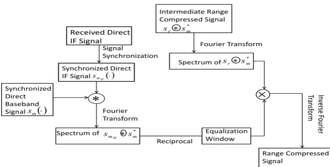
Based on the intermediate range compressed result (7), to suppress the compressed side lobes, spectrum equalization [11] is performed. Concerning applying spectrum equalization technique in this paper, the detailed procedure in the module ‘Spectrum Equalization’ in Figure2can be further presented as Figure3.
As we can see that in Figure3, Fourier transform of intermediate range compressed signal as (7) is conducted. The transformed result is expressed as follows
F[sr~s∗m]
=R0T−1Ar·Λ(t−τ(u)−τR(u))
×exp(j(2πfIF·t+φr(u)))
×exp(−j2πω·t)dt
= Ar·exp(jφr(u))
×sinc2(2π(fIF−ω))
(8)
Received Direct IF Signal
Signal
Synchronization Synchronized Direct IF Signal
IF
m
s
Synchronized
Intermediate Range Compressed Signal
* m
r s
s
Fourier Transform
Spectrum of srs*m
Synchronized Direct Baseband Signal sm
Fourier Transform
Spectrum of *
IF m
m s
s
Reciprocal
Inver
se
Fouri
er
Transf
orm
Range Compressed Signal
Equalization Window
Figure 3.The proposed range compression algorithm.
direct IF signalsmIF and the synchronized direct baseband signal sm. In Figure3, the synchronized direct IF signal is given as follows
smIF(t,u) =C[t−τ(u)]D[t−τ(u)]
×exp(j(2πfIF+fd)·t)
(9)
the correlated result betweensmIF andsmis given as smIF~s
∗ m
=Λ(t−τ(u))×exp(j2πfIF·t)
(10)
and the spectrum of the correlated result is the Fourier transform of (10), which can be expressed as
F[smIF~s ∗
m] =sinc2(2π(fIF−ω)). (11) Then the equalization window is designed as follows
W =
( 1
F[smIF~s∗m] =
1 sinc2(2π(f
IF−ω)), whenωe[−B,B]
0, Otherwise . (12)
The key step of spectrum equalization is performed as follows
F[sr~s∗m]×W
= (
Ar·exp(jφr(u)), when frequencye[fIF−B,fIF+B]
0, Otherwise .
(13)
The equalized result is a rectangular function at frequency domain, where the rising edge appears at the frequency fIF−Band the falling edge appears at the frequency fIF+B. And due to the fact
that spectrum equalization is conducted at frequency domain, side lobes of the reflected signals at different range positions can be suppressed simultaneously.
lower frequency component fIF−Bis filtered out. The final range compressed signal of Figure2and
Figure3is expressed as follows
F−1{F[s
r~s∗m]×W}
= Ar·exp(jφr(u))·(fIF+B)
×sinc[2π·(fIF+B)·(t−τ(u)−τR(u))].
(14)
In (14), the pulse duration is determined by the component fIF+B of the sinc(·) function term,
and can be derived as f 1
IF+B. Thus the attainable range resolution with regard to pulse duration is expressed as
δR2 = c
2·cos(β/2)·(fIF+B)
(15)
whereδR2denotes the range resolution obtained by the proposed algorithm. It can be seen that (15) is
1
1+fIF/B times superior than (5) provided by conventional range compression algorithm. Meanwhile, from (14), we can see that the reflected magnitude and phase information are still preserved.
However GNSS receivers have their certain sampling frequencies, which should be considered when determine the IF value for performing range compression. Denoting the sampling frequency of GNSS receiver as fs, according to sampling theory [22], the condition fIF+B ≤ 12fs should be
satisfied. And to make the proposed algorithm because effective, the condition fIF+B > Bshould
be satisfied at the same time as well. Therefore, all in all, the determination offIFvalue should satisfy
the following constraint
0< fIF≤
1
2fs−B. (16)
Finally, azimuth compression is conducted for forming the full GNSS-SAR image based on (14) with different phase valueφr(u)in azimuth domain.
4. The Simulation Experiment
To test the proposed algorithm for enhancing range resolution, simulations of the GNSS-SAR based on the standard GPS C/A code signal receiver configuration of ground moving mode is carried out in this section as examples. Since GPS receiver works in ground moving mode, the field of version (FOV) is mostly in horizontal, which can be considered as quasi-monostatic, the bi-static angleβcan be considered as zero [2]. Thus range resolutions of the conventional algorithm and the proposed algorithm are expressed as
δ
0
R1 = c
2B (17)
and
δ
0
R2 = c 2·(fIF+B)
(18)
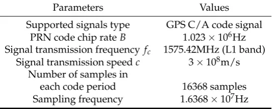
respectively. The parameter values of the standard GPS C/A code receiver is given in Table1.
Table 1.The parameter values of the standard GPS receiver configuration based GNSS-SAR
Parameters Values
Supported signals type GPS C/A code signal PRN code chip rateB 1.023×10⁶Hz Signal transmission frequency fc 1575.42MHz (L1 band)
Signal transmission speedc 3×10⁸m/s Number of samples in
Based on the sampling frequency value in Table 1 and the constraint (16), two different IF frequencies fIF1 = 2.092×10
6Hz and f
IF2 = 5.115×10
6Hz are employed in the simulation
tests. Theoretically the range resolution for the conventional algorithm can be achieved at 2cB =
3×10⁸
2×1.023×106 ≈150 m, while with the proposed algorithm in this paper, the resolution can improved to c
2·(fIF+B) =
3×10⁸
2×(2.092×106+1.023×10⁶) ≈50 m and 2·(fIFc+B) =
3×10⁸
2×(5.115×106+1.023×10⁶) ≈ 25 m for fIF1 and fIF2respectively. The verdict will be verified by the result with respect to range compressed pulse and the corresponding point spread function [11] shown in Figure4.
From Figure4, we can see that based on a standard GPS C/A code signal receiver, the range compressed pulse based on the proposed algorithm is around 3 times thinner and 6 times thinner than the conventional algorithm withfIF1 and fIF2, respectively.
To verify the proposed range compression algorithm, a simulation test is carried out. The simulation experiment is set out as shown in Figure5.
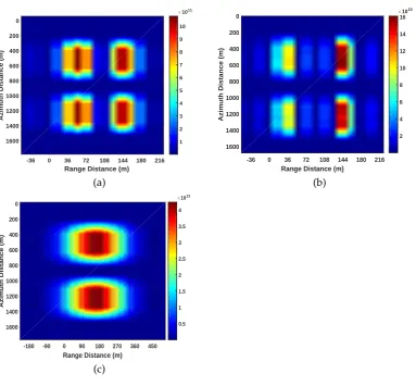
In Figure5, four strong reflection surfaces with 400 m long and 20 m width are arranged with 200 m along the azimuth direction and 108 m with the range direction. The direct and reflect signal antennae are moving along the azimuth direction with a constant speed to perform aperture synthetic. The GPS data are simulated using parameters listed in Table1. Based on the considered scenarios, the GNSS-SAR images generated by both the proposed range compression scheme and the conventional range compression scheme are shown in Figure6.
As can be seen in Figure6(a) and (b), due to the fact that the proposed scheme can offer a superior range resolution, the four scattering areas in Figure5can be well separated. Through the comparisons, Figure6(b) has a less range ambiguity because a higher IF value is employed at the GPS receiver. In Figure6(c), the two scatters located at different range domain cannot be separated on the GNSS-SAR image with the conventional range compression algorithms as the resolution of this approach is 150 m according to (17) withB=1.023 MHz.
In summary, the simulation results in this section has demonstrated that the proposed range compression algorithm can provide a superior range resolution than the conventional range compression algorithm.
Furthermore through tests, the proposed range compression algorithm is also applicable for the GNSS-SAR receiver based on the other GNSS signals of opportunity. Since for most GNSS signals receiver, the IF values are typically higher than the baseband frequency (which equals to PRN code chip rate), a superior range resolution should be achieved by employing the proposed algorithm. However because GNSS receivers differ in the PRN code types and IF values for signals receiving, the achievable range resolutions after improving will be different.
5. Discussion
Although the proposed algorithm can significantly improve range resolution of GNSS-SAR, according to Figure4 to Figure 6, it can be seen that the magnitude decreases with respect to fIF
values. This is because when performing spectrum equalization, Signal-to-Noise Ratio (SNR) will decrease with respect to the selected cutoff frequency [11].
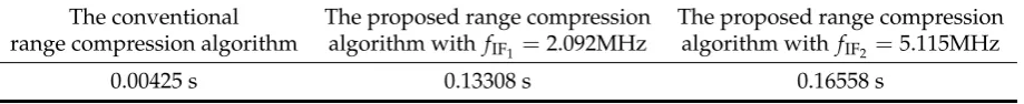
Meanwhile due to the fact that spectrum equalization is employed, range compressed delay of the proposed algorithm is supposed to be higher than convention range compression algorithm. According to machine running time, range compressed delay per azimuth bin with respect to the two algorithms is given as Table2.
Table 2.The average range compressed delay per azimuth bin
The conventional The proposed range compression The proposed range compression range compression algorithm algorithm with fIF1 =2.092MHz algorithm with fIF2 =5.115MHz
Range Distance (m)
-180 -135 -90 -45 0 45 90 135 180 225
Magnitude
0 2000 4000 6000 8000 10000
150 m
Range Distance (m)
-180 -135 -90 -45 0 45 90 135 180 225
Magnitude
500 1000 1500 2000
50 m
(a) (b)
Range Distance (m)
-126-108-90 -72 -54 -36 -18 0 18 36 54 72 90 108126144
Magenitude
20 40 60 80 100 120 140 160
25 m
Range Distance (m)
-180 -135 -90 -45 0 45 90 135 180
Azimuth Distance (m)
5
10
15
20
25
×109
0 0.5 1 1.5 2 2.5 3 3.5
(c) (d)
Range Distance (m) -180 -135 -90 -45 0 45 90 135 180
Azimuth Distance (m)
10
15
20
25
×108
0 0.5 1 1.5 2 2.5
Range Distance (m)
-126-108-90 -72 -54 -36 -18 0 18 36 54 72 90 108126144
Azimuth Distance (m)
10
12
14
16
18
20
22
24
26
×107
2 4 6 8 10 12 14 16 18
(e) (f)
Figure 4. (a) Range compressed pulse based on the conventional range compression algorithm; (b) Range compressed pulse based on the proposed range compression algorithm with fIF1 =
2.092MHz; (c) Range compressed pulse based on the proposed range compression algorithm with
fIF2 = 5.115MHz; (d) The point spread function of (a); (e) The point spread function of (b); (f) The
GPS satellite
Direct antenna Direct signal
Reflected Signal
The 4 Ground Scattering Areas
Figure 5.The simulation scenario.
Range Distance (m)
-36 0 36 72 108 144 180 216
Azimuth Distance (m)
0
200
400
600
800
1000
1200
1400
1600
×1011
1 2 3 4 5 6 7 8 9 10
Range Distance (m)
-36 0 36 72 108 144 180 216
Azimuth Distance (m)
0
200
400
600
800
1000
1200
1400
1600
×1010
2 4 6 8 10 12 14 16
(a) (b)
Range Distance (m)
-180 -90 0 90 180 270 360 450
Azimuth Distance (m)
0
200
400
600
800
1000
1200
1400
1600
×1013
0.5 1 1.5 2 2.5 3 3.5 4
(c)
Figure 6.(a) GNSS-SAR image generated by the proposed range compression algorithm with fIF1 =
2.092MHz; (b) GNSS-SAR image generated by the proposed range compression algorithm withfIF2=
As we can see that in Table2, range compressed delay increases with respect to IF value as well. Therefore in our future work, we would like to develop a mechanism for selecting the optimal IF value for GNSS-SAR receivers to trade-off among range resolution, range compressed SNR and compressed delay together with corresponding field experimental studies.
6. Conclusions
In this paper, a novel range compression algorithm for enhancing the resolution of GNSS-SAR is proposed. In range compression, the received reflected IF GNSS signal is correlated with the synchronized direct baseband signal in range domain for each azimuth bin. Then side lobes of the range compressed result are suppressed by a proper designed spectrum equalization window. Both theoretical derivation and simulation results have demonstrated that the proposed range compression algorithm can provide a superior range resolution than the conventional range compression algorithm in GNSS-SAR. At the same time, the proposed algorithm can improve range resolution without the need for generating full preliminary images.
Acknowledgments: The research was substantially by funded by the grants from The National Key Research and Development Program of China (No. 2016YFB0501803).
Author Contributions: Yu Zheng proposes the idea, conducts the theoretical derivation, simulations as well as carries out writing the paper. Yang Yang helps to discuss the related technical issues. Wu Chen revises the manuscript.
Conflicts of Interest:The authors declare that there is no conflict of interests.
Abbreviations
The following abbreviations are used in this manuscript:
GNSS Global Navigation Satellite System GPS Global Positioning System SAR Synthetic Aperture Radar IF Intermediate Frequency SNR Signal to Noise Ratio C/A code Coarse Acquisition Code P code Encrypted Precision Code FOV Field of Version
Bibliography
1. Zuo, R.Bistatic synthetic aperture radar using GNSS as transmitters of opportunity; PhD diss., University of Birmingham, 2012.
2. Zeng, Z. Passive bistatic SAR with GNSS transmitter and a stationary receiver; PhD diss., University of Birmingham, 2013.
3. Daout, F.; Schmitt, F.; Ginolhac, G.; Fargette, P. Multistatic and multiple frequency imaging resolution analysis-application to GPS-based multistatic radar. IEEE Transactions on Aerospace and Electronic Systems, 2012, 48(4), 3042–3057.
4. Mikawa, Y.; Ebinuma, T. and Nakasuka, S. The study of the remote-sensing application using the GNSS reflected signal with the aperture synthesis. 2012 IEEE International InGeoscience and Remote Sensing Symposium (IGARSS), 2012, 400–403.
5. Ebinuma, T.; Mikawa, Y. and Nakasuka, S. Quasi-monostatic algorithm for GNSS-SAR. 2013 IEEE Asia-Pacific Conference on InSynthetic Aperture Radar (APSAR), 2013, 164–166.
6. Lazarov, A.; Chen, V. C.; Kostadinov, T. and Morgado, J. P. Bistatic SAR system with GPS transmitter.2013 IEEE InRadar Conference (RADAR), 2013, 1–6.
8. Antoniou, M.; Hong, Z.; Zhangfan, Z.; Zuo, R.; Zhang, Q. and Cherniakov, M. Passive bistatic synthetic aperture radar imaging with Galileo transmitters and a moving receiver: Experimental demonstration.IET Radar, Sonar & Navigation, 2013, 7(9),985–993.
9. Antoniou, M. and Cherniakov, M. GNSS-based bistatic SAR: A signal processing view.EURASIP Journal on Advances in Signal Processing, 2013,(1), 98.
10. Santi, F.; Pastina, D.; Bucciarelli, M.; Antoniou, M.; Tzagkas, D. and Cherniakov, M. Passive multistatic SAR with GNSS transmitters: Preliminary experimental study.2014 IEEE 11th InEuropean Radar Conference (EuRAD), 2014, 129–132.
11. Ma, H.; Antoniou, M. and Cherniakov, M. Passive GNSS-Based SAR Resolution Improvement Using Joint Galileo E5 Signals.IEEE Geoscience and Remote Sensing Letters, 2015, 12(8), 1640–1644.
12. Ma, H.; Antoniou, M. and Cherniakov, M. Passive GNSS-based SAR imaging and opportunities using Galileo E5 signals.Science China Information Sciences, 2015, 58(6), 1–11.
13. Santi, F.; Antoniou, M. and Pastina, D. Point spread function analysis for GNSS-based multistatic SAR.
IEEE Geo-science and Remote Sensing Letters, 2015, 12(2), 304–308.
14. Zeng, T.; Zhang, T.; Tian, W. and Hu, C. Space-Surface Bistatic SAR Image Enhancement Based on Repeat-Pass Coherent Fusion With Beidou-2/Compass-2 as Illuminators. IEEE Geoscience and Remote Sensing Letters, 2016, 13(12), 1832–1836.
15. Zeng, H., et al. A Novel General Imaging Formation Algorithm for GNSS-Based Bistatic SAR.Sensors, 2016, 16(3), 294.
16. Santi, F.; Bucciarelli, M., Pastina, D.; Antoniou, M. and Cherniakov, M. Spatial resolution improvement in GNSS-Based SAR using multistatic acquisitions and feature extraction.IEEE Transactions on Geoscience and Remote Sensing, 2016, 54(10),6217–6231.
17. Shi, S.; Liu, J.; Li, T. and Tian, W. Basic performance of space-surface bistatic SAR using BeiDou satellites as transmitters of opportunity.GPS Solutions, 2016, 1–11.
18. Lv, G.; Wang, J. and Liu, X. Ground moving target indication in SAR images by symmetric defocusing.
IEEE Geoscience and Remote Sensing Letters, 2013, 10(2), 241–245.
19. Walterscheid, I.; Espeter, T.; Brenner, A. R.; Klare, J.; Ender, J. H.; Nies, H.; Wang, R. and Loffeld, O. Bistatic SAR experiments with PAMIR and TerraSAR-X—setup, processing, and image results. IEEE Transactions on Geoscience and Remote Sensing, 2010, 48(8), 3268–3279.
20. Rodriguez-Cassola, M.; Baumgartner, S.V.; Krieger, G.and Moreira, A. Bistatic TerraSR-X/F-SAR Spaceborne—Airborne SAR Experiment: Description, Data Processing and Results. IEEE Transactions on Geoscience and Remote Sensing, 2010, 48(2), 781—794.
21. Sklar, B.Digital communications, NJ: Prentice Hall, Jan. 1, 2001. 22. Sukhatme, B. V.Sampling theory of surveys with applications, 1954.
c