Experiments with an Entangled
System of a Single Atom and a
Single Photon
Wenjamin Rosenfeld
Experiments with an Entangled
System of a Single Atom and a
Single Photon
Wenjamin Rosenfeld
Dissertation
an der Fakultät für Physik
der Ludwig–Maximilians–Universität
München
vorgelegt von
Wenjamin Rosenfeld
aus Odessa
Zusammenfassung
Verschränkung ist eines der grundlegendsten Merkmale in der Quantenmechanik. Sie beschreibt einen nicht separierbaren Zustand von zwei oder mehr quantenmechanischen Objekten und besitzt z. T. Ei-genschaften, welche dem klassischen physikalischen Sinn widersprechen. Während das Konzept der Verschränkung, welches bereits von E. Schrödinger in 1935 eingeführt wurde, allgemein gut verstan-den ist, stellen die Erzeugung und Analyse von verschränkten Zustänverstan-den noch immer eine erhebliche Herausforderung dar. Insbesondere die Verschränkung von verschiedenartigen Objekten wie Atomen und Photonen wurde erst vor kurzem erreicht und ist Gegenstand aktiver Forschung.
Diese Arbeit berichtet über Experimente mit Verschränkung zwischen einem einzelnen Rubidium Atom und einem einzelnen Photon. Das Atom wird in einer optischen Falle gehalten, wo es exakt lokalisiert ist und sein interner Zustand mit Laserpulsen manipuliert werden kann. Zur Erzeugung der Verschränkung wird das Atom optisch in ein kurzlebiges höheres Niveau angeregt, von wo aus es unter Ausstrahlung eines einzelnen Photons zurück in den Grundzustand fällt. Die Polarisation des emittierten Photons ist verschränkt mit dem Spin des Atoms. In dieser Arbeit wurden Methoden ent-wickelt, die Präparation und Analyse des Atom-Photon Zustandes mit hoher Genauigkeit erlauben. Um den Zustand für weitere Anwendungen verfügbar zu machen, mussten mehrere Probleme gelöst werden. Erstens ist der interne Zustand des Atoms empfindlich gegenüber äußeren Störungen, ins-besondere durch magnetische und elektromagnetische Felder. Um den Zustand des Atoms während des Experiments (welcher auf der Skala von Mikrosekunden abläuft) zu erhalten, wurde u. a. ein Sy-stem zur aktiven Stabilisierung der Magnetfelder entwickelt. Zweitens muss das vom Atom emittierte Photon zu einem anderen Ort übertragen werden, dabei soll sein Zustand erhalten bleiben. Für diesen Zweck wurde eine faseroptische Strecke von 300 Metern Länge aufgebaut. Wegen der mechanisch bedingten Doppelbrechung in der Faser, ändert sich der Polarisationszustand des Photons während der Übertragung. Deshalb wurde ein System zur aktiven Kompensation der Doppelbrechung entwor-fen und installiert. Um die Zuverlässigkeit der optischen Verbindung zu bestätigen, wurde das vom Atom emittierte Photon übertragen und Verschränkung nachgewiesen.
Der neue Typ der Verschränkung hat viele Anwendungen, insbesondere im Bereich der Quanten-Informationsverarbeitung. Die Fähigkeit, Superpositionszustände und verschränkte Zustände zu spei-chern und zu verarbeiten, erlaubt effiziente Lösung von speziellen Problemen, welche auf klassischen Computern nicht innerhalb realistischer Zeit lösbar sind. Darüber hinaus erfordert und ermöglicht die quantenmechanische Natur dieser Information prinzipiell neue Methoden der Kommunikation (z.B. Quanten-Teleportation und Kryptographie). Ein Teil dieser Arbeit beschäftigt sich mit der Imple-mentierung des Protokolls zur Quantenteleportation an dem verschränkten Atom-Photon Paar. Ein Zustand, welcher auf das Photon kodiert wurde, konnte erfolgreich auf den atomaren Spin über eine Entfernung von 5 Metern teleportiert werden.
Entanglement is one of the most fundamental features in quantum mechanics. It describes a non-separable state of two or more quantum objects and has certain properties which contradict common physical sense. While the concept of entanglement between two quantum systems, which was in-troduced by E. Schrödinger in 1935, is well understood, its generation and analysis still represent a substantial challenge. Especially entanglement between objects of different nature like atoms and photons was achieved only very recently and is subject of current research.
This thesis presents experiments on entanglement between a single Rubidium atom and a single photon. The atom is stored in an optical trap where it is well localized and its internal state can be manipulated by laser pulses. For generation of entanglement the atom is optically excited into a short-lived upper level from where it falls back emitting a single photon whose polarization is entangled with the atomic spin. During this work methods were developed which allow to prepare and to analyze the atom-photon state with high accuracy. In order to make the entangled state available for further applications, several problems had to be solved. First, the internal atomic state is sensitive to external influence, in particular to magnetic and electromagnetic fields. To preserve the quantum state of the atom during the experimental time (which is of the order of microseconds) the external fields were compensated using a specially developed active stabilization system. The second problem is the communication of the photon to a different location. For this purpose an optical fiber link of 300 meters was set up. Since the polarization state of the photon is changed during propagation due to mechanically and thermally induced birefringence in the fiber, a system for an active maintenance of polarization was implemented. Atom-photon entanglement was distributed over this fiber link confirming its reliability.
The new type of entanglement has many applications, particularly in the field of quantum infor-mation processing and communication. The ability to store and process quantum superpositions and entangled states allows to efficiently solve certain problems which can not be solved on classical computers within reasonable time. Furthermore the quantum nature of this information requires and enables fundamentally new communication methods (e.g. quantum teleportation and cryptography). A part of this thesis was dedicated to an implementation of the quantum teleportation protocol on the entangled atom-photon system. A state encoded onto the photon was successfully teleported to the atomic spin over a distance of 5 meters.
Contents
1. Introduction 9
2. Atom-Photon Entanglement 12
2.1. Introduction . . . 12
2.2. The atomic qubit . . . 12
2.3. Principle of atom-photon entanglement. . . 14
2.4. A trap for single neutral atoms . . . 15
2.4.1. Principle of operation. . . 15
2.4.2. Vacuum chamber and optics . . . 16
2.4.3. Optical dipole trap . . . 17
2.4.4. Magneto-optical trap and loading of atoms . . . 18
2.4.5. Lasers . . . 20
2.4.6. Photon detection . . . 20
2.5. Generation of atom-photon entanglement . . . 21
2.6. Detection of the atomic state . . . 22
2.6.1. Hyperfine level detection . . . 23
2.6.2. STIRAP. . . 23
2.6.3. State selectivity . . . 25
2.6.4. Technical realization of the STIRAP process . . . 26
2.6.5. Detection accuracy and detection efficiency . . . 27
2.7. Experimental results . . . 28
2.7.1. Experimental sequence . . . 28
2.7.2. Atom-photon correlations . . . 29
2.7.3. Quantum state tomography of the entangled atom-photon state . . . 30
2.7.4. Violation of Bell’s inequality . . . 31
2.8. Summary . . . 32
3. Remote Preparation of an Atomic Quantum Memory 33 3.1. Introduction . . . 33
3.2. Theoretical scheme . . . 33
3.2.1. Quantum teleportation . . . 33
3.2.2. Remote State Preparation. . . 35
3.3. Experimental Realization . . . 37
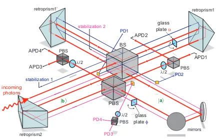
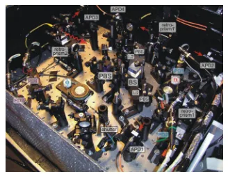
3.3.1. Double interferometer setup . . . 38
3.3.2. Interferometer stabilization . . . 41
3.3.3. Control of the interferometer phase . . . 44
3.3.4. Effects of birefringence in the setup . . . 45
3.4. Analysis of the experimental results . . . 46
3.5. Summary . . . 51
4. Coherence Properties of the Atomic Qubit 52 4.1. Introduction . . . 52
4.2. Mechanisms leading to dephasing . . . 53
4.3. Evolution of a spin-1 system in an effective magnetic field . . . 55
4.4. A model for dephasing . . . 56
4.4.1. Static field model . . . 56
4.4.2. Dynamic field effects . . . 58
4.4.3. The role of a magnetic guiding field . . . 60
4.4.4. Effect of the dipole trap upon the atomic state . . . 61
4.5. Measurement and active control of magnetic fields . . . 64
4.5.1. Active control of magnetic fields . . . 66
4.6. Experimental results . . . 68
4.6.1. Measurement of the state evolution . . . 68
4.6.2. Improvements due to stability of magnetic field and trap polarization. . . 69
4.6.3. Effect from polarization of the dipole trap light . . . 71
4.6.4. Effect of the guiding field . . . 72
4.7. Partial tomography of the state evolution . . . 72
4.8. Summary . . . 75
5. Distribution of Entanglement over Long Distance 77 5.1. Introduction . . . 77
5.2. Measurement of polarization drifts in optical fibers . . . 77
5.2.1. Reference polarimeter . . . 78
5.3. Active stabilization of fiber birefringence . . . 80
5.3.1. Polarization controller . . . 80
5.3.2. Parameter optimization algorithm . . . 81
5.3.3. Performance . . . 82
5.4. Atom-photon entanglement over 300 meter fiber. . . 83
5.5. Summary . . . 84
6. Summary and Outlook 85
A. Definition of light polarizations and atomic states 87
B. Quantum state tomography and quantification of state coherence 89
C. Distribution of potential energy of a single atom in a harmonic trap 92
D. Polarization effects in strongly focused beams 96
1. Introduction
Naozarnny ipotolok loilis~teni, skrewen~ruk,skrewen~nog, sud~byskrewen~.
B.Pasternak The study of single microscopic systems gives insight into the structure of our physical world at a very fundamental level. The elementary building blocks of matter, the atoms, as well as the units of electromagnetic field, the photons, obey the laws of quantum mechanics. This leads to many counter-intuitive consequences. One of the most interesting non-classical properties in quantum mechanics is entanglement. Two entangled particles are in a common, not separable quantum state even if they are spatially separated. This “non-local” behavior together with the inherent indeterminism (only probabilities of measurement outcomes can be predicted) led to serious doubts in the correctness of the quantum theory.
In 1935 Einstein, Podolsky and Rosen (EPR) formulated their famous question [1] on the com-pleteness of quantum mechanics, also known as the EPR-paradox. By requiring reality, locality and completeness, which are (according to EPR) necessary properties of any physical theory, they con-structed a gedankenexperiment apparently contradicting quantum theory. The contradiction can be solved by either abandoning the concept of reality or locality, or by extending the quantum theory with so-called local hidden variables (LHV). The LHV extension would make the theory local, real-istic and determinreal-istic.
In 1964 John Bell constructed an inequality, which allowed for the first time to distinguish quantum mechanics from any LHV theory, referred to as Bell’s inequality [2]. Based on this inequality an experimental test of LHV concepts was proposed [3]. Such test involves correlation measurements on a pair of entangled particles and predicts a limit for the outcome in LHV theory. This limit is violated by quantum mechanics. First experimental tests of Bell’s inequality [4,5, 6] supported the concept of quantum theory, however two fundamental issues, so-called “loopholes”, were not accounted for. First, such test requires strict independence of the two measurements (in the sense of special relativ-ity). This “locality loophole” was closed in an experiment with entangled photons [7] over a distance of400 m. Second, the test requires detection of at least 2
3 of the entangled pairs [8], otherwise, no
strict conclusions can be done on the whole ensemble. This “detection loophole” was closed in an ex-periment with two neighboring ions in a trap [9], however, the locality condition could not be satisfied due to small spatial separation of only fewµm. Until today no experiment has managed to close both loopholes at the same time. One possible solution is to entangle two atoms at a large distance, where the high atomic detection efficiency could be combined with the locality condition. Starting with two atoms, each entangled with a photon, the scheme of entanglement-swapping can be used to entangle the atoms [10].
qubits. In contrast to classical bits, which are well defined in one of their logical states (“0 “ or “1”), a quantum bit can also be in a superposition like √1
2(|0i+|1i). Additionally, while classical bits are
independent, several quantum bits can be in an entangled state. These unique properties of quantum mechanics allow to cardinally reduce the computational complexity of certain problems. Well-known examples are the factorization of large numbers [11] and database search [12]. Although a full-scale quantum computer is beyond reach of current technology, impressive experimental demonstrations of basic operations and elementary algorithms were already performed in nuclear magnetic resonance systems (NMR) [13], trapped ions [14] and trapped neutral atoms [15].
The main difficulty in the observation of quantum effects is to isolate a quantum system from the environment. Any interaction with the environment leads to a change of the quantum state and finally to the loss of coherence of superposition states. On the other hand any manipulation of the system requires an influence from outside. A compromise has to be found between the isolation of the system (and therefore the purity of its observation) and its controllability. Technological advances of recent years, such as laser cooling and trapping of individual neutral atoms or ions provide a well-isolated quantum system almost on demand. Furthermore, the techniques of spectroscopy and manipulation, e.g. with lasers and microwaves, allow to control the internal atomic states. These achievements make it possible to experimentally study one of the most fundamental systems - a single atom interacting with a single photon.
In this thesis I will describe experiments with a single, optically trapped neutral87Rbatom which
is entangled with a single photon. The quantum state is encoded in long-lived Zeeman substates of the atomic hyperfine ground level. The entanglement is generated by using spontaneous optical decay in aΛ-type system giving an entangled state between the spin of the atom and the polarization of the emitted photon [16]. This is one of the first systems where entanglement between light and matter was directly observed [17,18]. As well, this type of entanglement was generated with a single trapped
111Cd+ ion [19], and with a single 87Rb atom strongly coupled to a high-finesse optical resonator
[20]. Entanglement between a photon and a collective excitation in an atomic ensemble was reported in [21]. The first challenge of this work was characterize the entanglement and to make it available for further experiments. Chapter2describes the methods and techniques necessary for this task.
One of the most interesting experiments which can be performed with an entangled system is quan-tum teleportation. It allows to transfer the quanquan-tum state from one particle to another without need of direct interaction. From the point of view of quantum communication it solves the non-trivial problem of transferring an unknown quantum state which can not be directly inferred by a direct measurement. Chapter3describes the experimental realization of a protocol which is based on teleportation. Here the internal quantum state of the atom is prepared remotely by using its entanglement with the photon. The state is imprinted onto the photon by using an additional degree of freedom (spatial mode) and then teleported onto the atom. With our setup we demonstrate this so-called “remote state preparation” achieving a faithful mapping of photonic quantum states onto the atom.
For using the single trapped atom as a quantum memory device, as well as for experiments which require the ability to maintain the quantum state for a certain time, the coherence properties of the in-ternal atomic state are important. In general, the important parameters are the stability of the involved atomic states (which may decay) and their sensitivity upon external influence. The Zeeman states in our experiment are stable ground states, however, due to their magnetic moment they are influenced by external magnetic fields and by the optical field of the trap. These effects are studied in chapter
2.1. Introduction
Entanglement is one of the most striking features of quantum mechanics. It exhibits highly non-classical properties and has various applications in quantum information processing and communica-tion [22]. Furthermore it allows to increase the resolution in lithography and metrology [23]. The technology of entanglement generation has rapidly advanced in recent years. Generation of polar-ization entangled photons was already performed in 1960-ies using atomic cascade transitions [24]. Nowadays up to 6[25] entangled photons can be observed using the spontaneous parametric down-conversion (SPDC) technique, producing a variety of multi-particle entangled states [26]. The avail-ability of higher laser powers allows to increase the efficiency of this process and the number of entangled photons. On the other hand, big progress was achieved in trapping and manipulation of atomic systems. Entanglement of up to8 ions was produced [27] by using collective oscillation of ions in a trap and several thousand neutral atoms in an optical lattice were entangled using collisions [28].
Entanglement considered so far was only between objects of the same type (photon-photon or atom-atom). For future applications in quantum information and communication it is necessary to combine the advantages of atomic systems (long coherence times, advanced manipulation techniques, high detection efficiency) with that of photons (long-distance communication). Entanglement between atomic systems and photonic communication channels forms the necessary interface allowing a va-riety of new applications. The first direct observation of entanglement between light and matter was achieved between a single photon and a single trapped ion [19] and neutral atom [16]. Entanglement between photons and atomic ensembles was reported as well [21].
This chapter describes the generation and characterization of entanglement between the spin of a single trapped 87Rbatom and the polarization of a photon at a wavelength of 780 nm. In order to
achieve this task we use an optical dipole trap to isolate a single atom. Entanglement between the internal atomic state and the polarization of the photon is generated in spontaneous decay in aΛ-type transition. A novel detection method allows to perform quantum state tomography of the internal atomic state. Together with polarization analysis of the photon, full quantum state tomography of the entangled atom-photon state can be performed. Additionally, violation of Bell’s inequality with the atom-photon system was observed giving additional evidence of the underlying entanglement.
2.2. The atomic qubit
The ability to perform the necessary experimental tasks relies on the proper choice of the atomic system. For the purposes of our experiment it has to satisfy the following criteria:
2.2. The atomic qubit
52 S1/2
ï1 -1,
ñ
ï1 0,ñ
ï1 +1,ñ
+3 +2 +1 0 -1 -2 -3
52 P1/2
52 P3/2
F=1 F=2
mF
F’=1 F’=2 F’=1 F’=2
F’=0 F’=3
6.84 GHz 267 MHz 157 MHz 72 MHz
817 MHz
795 nm 780nm
D2
D1
ïñz
ï¯ñz
ï¯ñx
ïñx
ïñy
ï¯ñy
ï
ñ
zï¯
ñ
zFigure 2.1.: Energy levels of87Rb. Shown is the ground level52S
1/2 and the first two exited levels
52P1/2 and 52P3/2 with their respective hyperfine splittings. The qubit is encoded in the |F = 1, mF =±1i states of the ground level. The inset shows the Bloch sphere
representation of the atomic qubit states. The eigenstates ofσˆz-|↓izand|↑izare located
on the poles, while their superpositions - the eigenstates ofˆσxandσˆy - lie on the equator.
• the qubit states have to form aΛ-type system with an excited state for the generation of entan-glement
• the optical transitions for cooling, preparation, etc. have to be accessible with present laser technology
• the optical transition which generates the entanglement must have a wavelength suitable for communication over optical fibers
The element which has the required properties is Rubidium, 87Rb, which is an alkaline metal with a
single outer electron. It has a nuclear spinI = 32 leading to the ground state52S1/2with a hyperfine
splitting inF = 1andF = 2(see Fig.2.1). TheF = 1andF = 2hyperfine levels consist of3and5
Zeeman substates respectively. The first exited state is split due to the fine interaction into52P1/2and
52P3/2states with their corresponding hyperfine and Zeeman structure. For convenience we will use
for the ground hyperfine substates the symbol|F, mFiand for excited states
F′, m′
F′
. The optical dipole transitions from the ground state into exited state manifolds 52P
1/2 and 52P3/2 are called
theD1 and the D2 transitions, respectively. The corresponding transition wavelengths of 780 nm
respectively795 nmare accessible with well-established diode-laser technology and also suitable for communication over optical fibers. Additionally, single photon detectors with an efficiency of≥0.6
are available for this wavelength range.
This atom is especially well-suited for the purpose of our experiment because of the simplicity of itsF = 1ground level which has only three substates. The qubit is encoded into the two long-lived Zeeman states|F = 1, mF =−1iand|F = 1, mF = +1i, which are degenerate in absence of
F=1 F’=0
ï
ñz
ï¯ñz
52P3/2
52S1/2
ï1 -1,
ñ
ï1 +1,ñ
ï0 0,
ñ
ï1 0,
ñ
atom
single photons
z
Figure 2.2.: Principle of atom-photon entanglement. The exited atomic state|F′ = 0, mF′ = 0ihas
three possible optical decay channels. The polarization of the emitted photon is entan-gled with the final state of the atom. Coupling the emitted light into a single-mode fiber suppresses the collection of photons from theπ-decay. The common optical axis of the objective and of the optical fiber define the quantization axis z.
two states together with a selected excited state (e.g. 52P
3/2|F′= 0, mF′ = 0i) form a Λ-system,
which is a crucial element for the generation of atom-photon entanglement. In terms of a qubit we shall call these states|↓iz and |↑iz respectively, where the z-axis is the quantization axis, defined in the experiment by the photon collection optics. In this subspace, the standard formalism of a two-level systems can be applied. The basis states can be expressed as eigenstates of the Pauli operators
ˆ
σx,σˆy,ˆσz, also any state can be represented on the Bloch sphere as shown in Fig.2.1.
2.3. Principle of atom-photon entanglement
In our experiment atom-photon entanglement is generated in the spontaneous decay of an exited atomic state, see Fig.2.2. Starting with the state |F′ = 0, mF′ = 0i, which has a lifetime of26 ns,
the atom will decay optically into theF = 1manifold. The decay into the|1,−1iand|1,+1istates leads to emission of aσ+ orσ−photon (left- or right-circularly polarized), respectively, while in the
decay into the|1,0i state a photon withπ-polarization (linear, along quantization axis) is emitted. This corresponds to the conservation of angular momentum since aσ-photon carries one unit of~and
aπ-photon has an expectation value of the (internal) angular momentum equal to zero. In the case of complete degeneracy of the two qubit states both decay channels have the same energy.
The emitted light is collected by a microscope objective and coupled into a single mode optical fiber. It is important to note that this step filters out the light from the π-transition. The reason is that the spatial emission function of theπ-transition (corresponding to emission of a dipole oscillating exactly along the quantization axis) is antisymmetric with respect to the quantization axis. Therefore, this light is not coupled into the optical fiber whose mode-function (Gaussian T EM00) is symmetric
[18]. This result is valid for any aperture size of the collecting objective.
2.4. A trap for single neutral atoms
Ψ+= √1
2 |1,−1i
σ++|1,+1iσ− (2.1)
The phase between the two components is determined by the Clebsch-Gordan coefficients of the optical transition [29]. The restriction to the two decay channels leads to the generation of a perfectly entangled state between the atomic qubit encoded in the spin and the polarization of the photon. This generation process is probabilistic because the spontaneous emission is not directed. The efficiency therefore depends on the numerical aperture of the collecting objective together with the coupling efficiency into the single-mode optical fiber.
2.4. A trap for single neutral atoms
For the experimental realization of atom-photon entanglement, as well as for any experiment with a single atom, the first requirement is to trap and to isolate a single atom. Furthermore the atom has to be accessible for manipulation and detection. The trap has to provide sufficient holding time and to preserve the internal atomic state. The possible candidates for trapping of single atoms are magneto-optical trap (MOT), magnetic trap and magneto-optical dipole trap. The MOT relies on forces resulting from scattering of light, and therefore does not preserve the internal state. The magnetic trap is state de-pendent - it uses magnetic polarization of the atom, so it can not trap both of the Zeeman states which constitute the qubit. The only available trapping principle which is capable to fulfill our requirements is based on the optical dipole force.
2.4.1. Principle of operation
The origin of optical dipole force is the well-known effect of interaction of an electrically polarizable medium with an electric field. It leads to an attraction (repulsion) of the medium into the region of the strongest electric field where its energy is the lowest (highest). In the optical case it is the interaction of the oscillating atomic electric dipole moment which is induced by the light field with the driving electric field itself. In the case of red-detuning, i.e. the frequency of the incident lightωLbeing below
any of the atomic transition frequencies, the driving electric field and the atomic dipole will oscillate in phase. This leads to an attractive force towards the region of highest light intensity.
In quantum mechanics this effect is called AC-Stark shift and leads to lowering of the atomic ground state energy, which is equivalent to the presence of an attractive potential. The depth of the potential depends on the light intensityI and the detuning from the resonance∆ :=ω0−ωL, whereω0is the
atomic transition frequency andωLthe frequency of light. In the case of a two-level atom one easily
gets the relation for the energy shift ∆E of the atomic states by diagonalization of the interaction Hamiltonian. For large detuning this so-called light-shift is given by
∆E=∓~Ω
2
4∆
whereΩ := 1~E·dis the Rabi frequency which depends on the electric field amplitudeEand the atomic dipole moment d. For red detuning, i.e.ωL < ω0, the ground state is lowered leading to the dipole
potentialUdipole ∼ ∆I, the excited state is shifted in opposite direction. In a real atom several ground
and excited state exist, and the coupling of each transition to the optical field contributes to the energy shift. In the limit of large red detuning in87Rb one considers only the coupling of the ground level
52S
DE
wL U0
a) b)
e
ñ
ï
g
ñ
ï
e’
ñ
ï
g’
ñ
ï
Figure 2.3.: Light-shift in a two-level atom. Interaction with light of frequency ωLfar detuned from
the atomic resonance shifts the atomic states (a). In case of red-detuning this shift can be used for trapping in e.g. Gaussian light-field configuration (b). The trapping potentialU0
is proportional to the light intensity.
is not resolved). In this case the light-shift of the atomic ground level for linear light polarization is given by:
Udipole = ∆E=−
πc2
2 ΓD
ωD3
1 ∆D1
+ 2
∆D2
·I (2.2)
whereΓDare the scattering rates,ωDthe resonance frequencies and∆D the detunings for theD1and
theD2transitions respectively. The factor ΓD ω3
D
is equal for both transitions.
In order to use this effect for atom trapping one has to create a light field configuration with (at least one) local maximum of intensity. A simple and convenient configuration is a focused Gaussian beam. The confinement depends then on the focusing parameters, i.e. on the waistw0of the beam and
its Rayleigh range zR. As will be shown in the following sections, the dipole trap can be arranged to
capture single atoms and to provide excellent optical access for laser manipulation and detection.
2.4.2. Vacuum chamber and optics
The storage time of atoms in the dipole trap is limited mainly by collisions with the background gas, therefore the experiment has to be performed under ultra-high vacuum conditions. For this purpose we use a spectroscopy glass cell (Hellma, uncoated) which is attached to a vacuum chamber and allows a compact setup with a very good optical access. The cell has inner dimensions of25×25×70 mmwith
2.5 mmglass thickness. It contains a Rubidium dispenser operated at a current of2.4 Aproviding a source of thermal Rubidium atoms. An ion-getter pump (Varian StarCell,24 l/s) as the final stage of vacuum pumping achieves a pressure below10−11mbarproviding a trap lifetime of several seconds [17].
The optics is located outside of the vacuum chamber as shown in Fig.2.4. It consists of a com-mercial objective (Linos HALO) with a numerical aperture of0.38and a working distance of30 mm
2.4. A trap for single neutral atoms
DM
objective 1 single-mode
fiber
dipole trap beam cooling
beams
Rb-dispenser
to detection objective 2
glass cell
PD
STIRAP beam
l/2
l 4/
phase comp.
fluorescence
excitation
l/2
APD1 APD2
PBS l/4
detection
cooling beamsoptical
pumping
push-outfront view
IF IF
DM
magn. sensor
z y
z x
Figure 2.4.: Schematic of the main experimental setup. Shown is the top view of the glass cell and the optics. The insets show the front view of the glass cell and the photon detection part. DM - dichroic mirror; PD - photodiode; APD - avalanche photodiode; IF - interference (here band-pass) filter; PBS - polarizing beam splitter;λ/2, λ/4- half- and quarterwave plates.
2.6.2) onto the atom.
2.4.3. Optical dipole trap
The dipole trap is operated at the wavelength of 856 nm having a red detuning of76 nm from the
D2-line (780 nm) and61 nmfrom theD1-line (795 nm). The light for the dipole trap is generated by a single frequency mode laser diode which achieves a maximum power of200 mW. The beam is first coupled into a single-mode optical fiber in order to achieve a pure Gaussian mode profile at the output. The trap beam is focused to a waist w0 = 3.5µmwith a Rayleigh rangezR = 45µm. For a typical
light power of 30 mWat the position of the trap this yields a depth of the potential U0 = 0.65 mK
corresponding to the ground state light-shift of13.6 MHz. The corresponding radial and axial trap frequencies are
ωr=
q
4U0
m·w2 0
= 2π·22.7 kHz
ωz =
q
2U0
m·z2 R
= 2π·1.25 kHz (2.3)
respectively. In order to keep the depth of the potential constant, the intensity of the trapping beam is continuously monitored by a photodiode (Fig.2.4) and stabilized by means of a feedback loop.
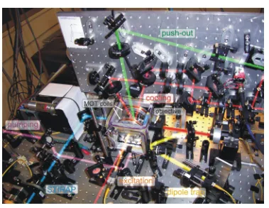
Figure 2.5.: Picture of the main experimental setup.
trap volume it is necessary to provide a high density of cold atoms (Ethermal < U0). Both tasks can
be achieved with the help of laser cooling and a magneto-optical trap as described in the following.
2.4.4. Magneto-optical trap and loading of atoms
In order to create locally a high density of cold atoms we use a magneto-optical trap (MOT). The MOT is created by overlapping three pairs of counter-propagating beams which are red detuned with respect to an atomic transition. The Doppler effect leads in this case to a predominant scattering of light from the direction opposite to the motion of the atom [30, 31]. This results in slowing, i.e. cooling of atoms. A proper choice of the polarization of the counter-propagating beams together with an applied magnetic quadrupole field leads also to a spatial confinement of the atoms [32]. To achieve continuous cooling the laser is tuned to the red of the closed atomic transition1 52S
1/2|F = 2i→
52P3/2|F′ = 3i.
The quadrupole magnetic field for the magneto-optical trap is produced by a pair of coils in anti-Helmholtz configuration. These are operated at 0.5..1 A, providing gradients of magnetic field of typically2.5..5 G/cm. Together with three pairs of counter-propagating cooling beams (see Fig.2.4) we hereby create a cloud ofRbatoms with a diameter of about1 mm. The cloud contains several ten thousand atoms at a temperature of about105µK[18]. This temperature is below the limit achievable
1Closed transition means that from the52P
3/2|F′= 3ilevel the atom should always decay back to the52S1/2|F= 2i
level and thus stay in the cooling cycle. This is not exactly true as there is a small probability of excitation of the
52
P3/2|F′= 2ilevel from which a decay to5 2
S1/2|F= 1iis possible. If this happens, the atom stops scattering
light and therefore cooling breaks down. To avoid this the atom is put back into the cooling cycle by applying an additional “repump” laser tuned to the52
S1/2|F = 1i →5 2
2.4. A trap for single neutral atoms
0 50 100 150 200 250 300 350
0 10 20 30 40 50 60
time (s)
countsin60ms
Figure 2.6.: Fluorescence observed from the single-atom dipole trap loaded from a MOT and contin-uously illuminated by cooling light. In this selected trace a two-atom loading event can be observed where both atoms stay in the trap long enough that an increased fluorescence level can be detected (peak neart= 21 s).
with ordinary laser cooling (Doppler limit for 87Rb is 146µK) due to the effect of
polarization-gradient cooling [33].
The loading of atoms into the dipole trap is accomplished by operating the magneto-optical trap and the optical dipole trap simultaneously. The position of the MOT is adjusted such that its center coincides with the focus of the dipole trap. In this case the MOT provides a high local density of cold atoms and a friction force (cooling) which allows to capture atoms in the conservative dipole potential. Fig.2.6shows a typical trace of fluorescence coming from the dipole trap during its loading from the MOT. The loading process is supervised by a computer control program which continuously records the counts from the photon detectors and adjusts the experimental parameters. After a step-like increase in fluorescence is detected, indicating the presence of the atom in the dipole trap, the computer control switches off the quadrupole fields of the MOT. The atom is further illuminated by the cooling light until it is lost from the trap. We observe a lifetime of2..4 s depending on cooling parameters. Under real experimental conditions, where different steps of optical pumping, excitation and cooling are applied, the lifetime reduces to 1.5..2 s which is still completely sufficient for all experiments.
52S1/2
52 P1/2
52 P3/2
F=1 F=2 F’=1 F’=2 F’=1 F’=2
F’=0 F’=3
CL RP
ST1 ST2 PMP1 PMP2
EXC DET
856nm
DT
Figure 2.7.: Overview of laser frequencies used in the experiment. All frequencies are derived from diode lasers by means of acousto-optical modulators. DT - dipole trap; CL - cooling laser; RP - repump laser; PMP1, PMP2 - optical pumping; EXC - excitation for entanglement generation; DET - hyperfine state detection push-out beam; ST1, ST2 - STIRAP.
2.4.5. Lasers
The laser frequencies used in the experiment are generated by 6diode lasers. Except for the dipole trap laser, all of them are set up with an external diffraction grating in Littrow configuration. The sta-bilization of the frequency is performed either directly to an atomic resonance line via FM saturation spectroscopy[41,42] in aRbgas cell, or indirectly to an already stabilized laser using the frequency offset lock technique. We achieve a laser stability of about700 kHzshort-term (coming from the fast phase noise of the laser diode) and about2 MHzlong-term. The long-term stability is limited by tem-perature drifts of the laser diodes and of the stabilizing electronics. Our laboratory is equipped with a common split air conditioner keeping the temperature constant to1◦..2◦C. Altogether the stability of
the lasers allows measurement times without human interrogation of up to24hours.
The exact frequencies and pulse shapes are generated by means of acousto-optical modulators (AOMs). They allow to shift the frequency of the incoming light by up to±300 MHzand to switch it on and off within∼10 ns. Most of the AOMs are set up in the so-called double-pass configuration where the light is sent through the modulator twice. This allows to achieve an isolation (suppression of residual light power) of better than100 dB. The control of the AOMs on the slow timescale (∼ms) is performed by a computer. For the time-critical parts of the experimental sequence a programmable pattern generator [43] is used, which has a time resolution of20 ns.
2.4.6. Photon detection
The detection is performed by two single-photon counting modules (Perkin-Elmer SPCM AQR-14 Si avalanche photodiodes with a circuit for active avalanche quenching). They have a quantum efficiency of 0.6and dark count rates of70..100 cps. The detectors are protected from unwanted light by band-pass interference filters. The overall efficiency for detection of the emitted photons is composed of the collection efficiency of the objective and coupling into the single-mode fiberηcoupl ≈0.63%,
transmission of the optical components (glass cell, objective, dichroic mirror, fiber, interference filters)
2.5. Generation of atom-photon entanglement
rate of∼3200 cpson the detectors (Fig.2.6) which allows to detect the presence of an atom within few tens ofms.
In order to analyze the polarization of the emitted photons we use a polarizing beam-splitter (PBS), see inset in Fig.2.4. The selection of the photonic measurement basis is done by means of a halfwave-and a quarterwave-plates mounted on motorized precision rotation stages. For a faithful analysis it is crucial to preserve the polarization of the photon on its way to the detectors. However, the birefringence of certain elements - the glass-cell, the dichroic mirror and the optical fiber changes the polarization depending on mechanical stress and ambient temperature. In order to compensate these effects, reference light of two complementary polarizations (V and+45◦) was sent through the
glass cell and coupled into the collection objective. By using a manual fiber polarization controller the output polarization was adjusted to be equal to the input (extinction of the wrong polarization of
1 : 1000 and better). For the short (5 m) optical fiber which is fixed to the optical table and stable temperature conditions in the laboratory this procedure has to be repeated once in several weeks. An automatic version of this procedure, which enables us to distribute entanglement over a 300 mlong optical fiber, is presented in chapter5.
2.5. Generation of atom-photon entanglement
After the atom has been loaded into the dipole trap, the experimental entanglement sequence is ini-tialized. It consists of three steps.
1. Preparation of the initial state.For efficient optical excitation the atom is first prepared in the |F = 1, mF = 0istate by optical pumping, Fig.2.8(a). This is done by applying π-polarized
light resonant with the F = 1 → F′ = 1 transition (pumping1), for which the transition |F = 1, mF = 0i → |F′ = 1, mF′ = 0i is forbidden. In order to empty the F = 2 state we
additionally apply light which is resonant with the F = 2 → F′ = 1transition (pumping2)
together with cooling light. For this light configuration the population gets “trapped” [36] in the dark state|F = 1, mF = 0i. This procedure has an efficiency of about65%mainly limited
by polarization errors and residual magnetic fields. The time required for the optical pumping depends on the initial state of the atom. During repeated excitation cycles the population stays inF = 1level and is efficiently pumped into|F = 1, mF = 0istate within about2.6µs. After
the cooling cycle, however, the population is in the F = 2level. Due to the presence of two dark states for the pumping2 light this level can not be completely emptied by this light alone. In order to empty the dark states, cooling light is used in addition, allowing to pump into the |F = 1, mF = 0istate in4.4µs.
2. Optical Excitation. The atom is excited into the |F′= 0, mF′ = 0i state by an optical π
-pulse, Fig.2.8(b). For this purpose a 20 nslong pulse resonant with the|F = 1, mF = 0i →
|F′= 0, mF′ = 0itransition is applied. Its intensity is adjusted such that within its duration the
atom undergoes half of a Rabi-cycle and ends up in the|F′ = 0, mF′ = 0istate. The efficiency
of this process is about95%.
3. Observation of the spontaneously emitted photon. The excited state has a lifetime of26 ns
52
S1/2
ï1 -1, ñï1 0,ñï1 +1, ñ 52
P3/2
F=1 F=2 F’=1 F’=2 F’=0 F’=3
ï1 -1, ñï1 0,ñï1 +1, ñ 0 25 50 75 100 125 150 time (ns)
0 100 200 300 400
counts
pumping1
pumping2
a) b) c)
cooling
Figure 2.8.: The entanglement sequence. In the first step (a) the atom is prepared in the |F = 1, mF = 0istate by optical pumping. This is done by applying two pumping lasers
assisted by the cooling laser, the only dark state for this configuration is the desired state. After optical excitation (b), the spontaneously emitted photon is detected. c) Time his-togram of spontaneously emitted photons. The exponential fit (blue curve) gives a lifetime of27.2 ns, which is in a good agreement with the theoretical value of26.2 nsof theD2
transition.
the efficiency of preparation of the initial state and the excitation (about60%). Altogether the efficiency to detect a single photon from the entanglement process isη= 0.12%.
The polarization state of the photon can be conveniently analyzed by means of a polarizing beam splitter (PBS) together with a halfwave-plate and a quarterwave-plate. It allows to perform a projective measurement in any basis. To achieve the same ability for the atomic spin state, a rather elaborate method is required, which is described in section2.6.
2.6. Detection of the atomic state
In order to analyze the entanglement of the atom with the photon or to perform any quantum-information protocol on the atom one needs the ability to analyze the atomic qubit in any desired measure-ment basis. In our case we have to distinguish between selected superpositions of the states in the {|1,−1i,|1,+1i}subspace with high efficiency. Conventional spectroscopy as, e.g., the shelving method known from experiments with trapped ions [37, 38] is not applicable here since it relies on scattering of photons on a closed transition. For this procedure the light has to be applied from a defined direction thereby inducing a directed force. The relatively deep potential of an ion trap is suf-ficient to prevent the ion from being pushed out during the detection process. However, in the much weaker potential of a dipole trap the light pressure leads to the loss of the atom before it can scatter sufficient amount of photons for detection. Thus a novel detection method had to be developed which is compatible with the shallow potential of a dipole trap.
The fact that resonant light pressure pushes the atom out of the trap can be applied for an efficient way to distinguish two different hyperfine levels, hereF = 1andF = 2(see section2.6.1). In order to adapt this technique for our experiment we first need a way to transfer a certain superposition from our analyzed subspace ofF = 1toF = 2. This can be done very efficiently using the so-called tripod STIRAP technique [39,40,16] which is described in section2.6.2.
2.6. Detection of the atomic state
52
S1/2
ï1 -1, ñï1 0, ñï1 +1, ñ 52
P3/2
F=1 F=2 F’=1 F’=2
F’=0 F’=3
push-out
a) b)
50 100 150 200 250 300 350 0
100 200 300 400
counts in 60 ms
numberofevents
atom in atom out
0
Figure 2.9.: Hyperfine state detection. By applying light resonant toF = 2→ F′ = 3transition the
population inF = 2level is pushed out of the trap (a). In the subsequent illumination of the trap with cooling light it is possible to distinguish whether the atom has left the trap or not by counting fluorescence photons (b).
In the second step the population inF = 2is removed from the trap. By observing the fluorescence from the trap it is then possible to decide whether the atom was removed or not, and thereby to infer in which superposition it was. In the following I will describe the state detection method in more detail.
2.6.1. Hyperfine level detection
The hyperfine level detection procedure uses resonant light pressure in order to remove population in theF = 2level out of the trap. It consists of a10µs longσ+- polarized “detection pulse” which is
resonant with theF = 2→ F′ = 3transition, Fig.2.9(a). The atom in theF = 2state scatters light on this closed transition and is pushed out of the trap. At the same time the atom in theF = 1level does not scatter because of the large detuning (6.8 GHz) and thus remains in the trap. After the pulse the cooling and repump light of the MOT is switched on and the presence or absence of the atom is verified. Fig.2.9(b) shows the histogram of fluorescence collected in60 msafter this procedure. The two events “atom out of the trap” and “atom still in the trap” are clearly separated. However, there is a final probability for the atom which survived the push-out to get lost during the fluorescence detection due to background collisions, etc. In order to reduce the errors of discrimination arising from such losses, the fluorescence collection time is reduced to20−25 ms. The discrimination accuracies (i.e. the probabilities to identify theF = 1andF = 2levels correctly) were determined [18] to be
F = 1 : ≥96.3±0.2% (2.4)
F = 2 : ≥99.3±0.1%
2.6.2. STIRAP
ïe
ñ
ïb
ñ
ïf
ñ
W1 W2
time
population inïfñ
0 0.2 0.4 0.6 0.8 1 W1 W2 a) b)
t0 t1 t2 t3 t4
Figure 2.10.: Principle of STIRAP. a) The initial state |bi and the final state |fi are coupled to an excited state|eiby two fields with Rabi frequenciesΩ1 (historically called pump) and
Ω2 (Stokes). b) By variation of the Rabi frequencies the population is adiabatically
transferred from|bito|fi.
STIRAP (stimulated Raman adiabatic passage) is a method for efficient transfer of population be-tween two states. It can be explained on a 3-level system with two ground states|bi,|fiand one exited state|ei, see Fig.2.10(a). The levels are coupled resonantly by two light fieldsST IRAP1and
ST IRAP2with respective Rabi frequencies Ω1and Ω2. The Hamiltonian in the interaction picture
(without spontaneous decay) is given in the{|bi,|fi,|ei}-basis by
b
Hint=
~
2
0 0 Ω1
0 0 eiβΩ
2
Ω1 e−iβΩ2 0
where β is the starting phase between the two fields. For given values of the Rabi frequencies, the eigenstates of the interacting system are
|Ψ1i= √ 1 Ω2
1+Ω 2 2
Ω2|bi −Ω1eiβ|fi
|Ψ2i= √2√Ω12 1+Ω
2 2
Ω1|bi+eiβΩ2|fi+
p
Ω21+ Ω22|ei
|Ψ3i= √ 1 2√Ω2
1+Ω 2 2
Ω1|bi+eiβΩ2|fi −
p
Ω2
1+ Ω22|ei
The state|Ψ1iis especially interesting because it contains no contribution from the exited state|ei,
therefore it is not affected by spontaneous emission. The ratio of populations of|biand|fiin|Ψ1iis
equal to Ω21
Ω2 2 .
The adiabatic theorem of quantum mechanics states that if a system is initially in an eigenstate of a Hamiltonian and if this Hamiltonian changes slowly compared to the dynamics of the system (given in our case byΩ1 and Ω2) then the system will follow the change of the eigenstate. By tailoring
the (time-dependent) Hamiltonian in a proper way it becomes possible to steer the system between different states with very high efficiency. In our case one has to adiabatically vary the ratio Ω1
Ω2 between
0and∞.
We start with the system in the initial state|biand both coupling fields off, i.e.Ω1(t0) = 0 = Ω2(t0)
(Fig.2.10(b)). Then the second field Ω2 is adiabatically switched on whileΩ1 stays zero, therefore
|Ψ1i(t1) =|bi. In the next phase the first field is also switched on, |Ψ1ibecomes a superposition of
|biand|fiwith the amplitude ratio Ω1
2.6. Detection of the atomic state
52 S1/2
ï1 -1,
ñ
ï1 0,ñ
ï1 +1,ñ
52P1/2
F=1 F=2 F’=1 F’=2
W2 W1
ïb
ñ
ïdñ
ï1 -1,
ñ
ï1 0,ñ
ï1 +1,ñ
F=1 F=2 F’=1 F’=2
W2 W1
ïb
ñ
ïd
ñ
W2
a) b)
ï1 -1,
ñ
+
ï1 +1,ñ
ï1 -1,
ñ
-
ï1 +1,ñ
Figure 2.11.: State selectivity of the STIRAP process for the cases of circular polarization (a) and linear polarization (b) of the STIRAP light. For each polarization of the applied STIRAP light there exist a bright state|bi, which is transferred, and a dark state|di, whose transfer is forbidden.
Ω1 can also be switched off, the system stays in|fi. By these means the population is adiabatically
transferred from|bi to|fi. Note that as long as the adiabaticity condition is satisfied, the state|ei
only mediates the coupling but is not populated during this process. Also the initial phaseβ has no effect (except a phase in the eigenstates), however it must remain constant during the process, i.e. the two fields have to be coherent for the duration of the transfer. Under ideal conditions the transfer efficiency is equal to unity and is not influenced by spontaneous decay of the state|ei.
2.6.3. State selectivity
In order to select the measurement basis of our qubit, the transferring process has to distinguish be-tween superpositions of states in the{|1,−1i,|1,+1i}space. This can be achieved by using selection rules of atomic transitions. Any polarization of theST IRAP1light field can be expressed as a super-position ofσ+andσ−polarization. There exists a superposition of|1,−1iand|1,+1istates which couples to this field, this state is called a bright state|bi. The orthogonal superposition does not cou-ple to the field and is called a dark state|di. Under these conditions the bright state|bi will evolve as described in the previous section (i.e. it will be transferred) while the dark state|di ideally stays unchanged (Fig.2.11).
For the state transfer we use the|F′ = 1, mF′ = 0i state of 52P
1/2 as the mediating upper state
|ei. The reason to use this state is the simplicity of the52P1/2 manifold which has only two levels
with large separation of817 MHzcompared to the four levels with smaller separations of52P3/2 (see also Fig.2.1), this allows to reduce unwanted coupling via different upper levels. TheST IRAP1
field is resonant with the|F = 1i → |F′ = 1itransition and theST IRAP2field is resonant with the |F = 2i → |F′ = 1itransition.
First we consider the case where the fieldST IRAP1givingΩ1isσ+-polarized, Fig.2.11(a). Here
it is easy to see that |di = |1,+1i and |bi = |1,−1i. In the second case shown in Fig. 2.11(b) theST IRAP1field is polarized asH = √1
2(σ
+ +σ−) (tripod STIRAP). Due to the fact that the
transition amplitudes (Clebsch-Gordan coefficients) of |1,−1i → |1′,0i and |1,+1i → |1′,0i are of opposite sign, in this case we get|di = √1
2(|1,−1i+|1,+1i)and|bi = 1
√
Generally, for a given polarization of theST IRAP1field
P= cos(α)σ++eiφsin(α)σ− (2.5)
we can write the dark state as ([18])
|ΨDi= cos(α)|1,+1i+eiφsin(α)|1,−1i. (2.6)
In order to complete the picture it has to be added that the population in the|1,0i state (if present) is transferred to|F = 2i for any polarization of the form (2.5), as the state |1,0i is only dark for
π-polarization. Since the population in |F = 2i will be removed from the trap in the next step, the whole procedure works as projection onto the dark state|ΨDi. See also appendixAfor the definitions
of polarizations and analyzed states.
Off-resonant transitions
So far we have considered only resonant coupling to the52P
1/2,|F′= 1ihyperfine level during the
STIRAP process. Unfortunately, off-resonant coupling via the|F′ = 2ilevel is present as well. The transition amplitudes |1,−1i → |2′,0i and |1,+1i → |2′,0i in this case have the same sign (in contrast to the opposite sign of |1,−1i → |1′,0i and |1,+1i → |1′,0i). This allows the transfer of the state|di while forbidding the transfer of the state|bi. Although this coupling is weaker than the resonant coupling of the |bi state, it can still lead to a considerable transfer efficiency as will be shown in the next section. By properly selecting the relative polarizations of ST IRAP1 and
ST IRAP2fields it is nevertheless possible to suppress the off-resonant two-photon transition [18]. The remaining error is then due to the imperfect preparation of the polarization of the two fields.
2.6.4. Technical realization of the STIRAP process
In order to generate theST IRAP1andST IRAP2fields we use two independent diode lasers spec-troscopically stabilized to the corresponding transitions (see also section2.4.5). The short-term rela-tive stability is of the order of700 kHzcorresponding to a time of 1
2π·700 KHz = 227 nsduring which
the relative phaseβ can be considered fixed. As a well-defined phase dependence between the two fields is needed for the duration of the transfer process, the pulse sequence has to be on a much shorter time scale.
We have chosen the pulse length of 30..40 ns. Each pulse is formed by an AOM in double-pass configuration allowing to switch the pulse on or off in about10 ns. The form of the rising and falling edges is smoothened by appropriate shaping of the electric signal which controls the AOMs with a low-pass filter. Fig.2.12(a) shows the measured intensity of the pulses. The relative intensities of the pulses are chosen such that the resulting maximal Rabi frequencies are approximately equal.
Then the two pulses are combined on a beam splitter, guided through a single-mode optical fiber, and sent through an additional AOM. This step is necessary to get a sufficient on/off switching ratio for the STIRAP field, which has up to 10000times the saturation intensity Isat. The high intensity
is needed in order to fulfill the adiabaticity condition. After that the pulse is coupled again into a single-mode optical fiber and guided to the main experiment (see Fig.2.4). There it passes a quarter-wave plate and a half-quarter-wave plate in order to prepare the polarization and thus to select the atomic measurement basis. A phase compensation plate is used to eliminate the phase betweenH and V
2.6. Detection of the atomic state
time (ns)
intensity(a.u.)
STIRAP2
STIRAP1
a) b)
1 10 100 1000
0.2 0.4 0.6 0.8 1
0
transferef
ficiency
intensity (I/I )sat ï1 +1,
ñ
+
ï1 -1,ñ
ï1 +1,
ñ
-
ï1 -1,ñ
Figure 2.12.: a) The experimental STIRAP pulse sequence - intensities ofST IRAP1andST IRAP2
beams measured by a fast photodiode. b) The transfer efficiency of the STIRAP process for the bright state √1
2(|1,+1i+|1,−1i)(blue curve) and the dark state 1
√
2(|1,+1i −
|1,−1i) (red curve). The polarization of both STIRAP lasers in this measurement is
V = √i
2(σ
+−σ−). The non-vanishing probability for the transfer of the dark state is
due to polarization errors which allow off-resonant coupling.
In order to test the STIRAP process the states√1
2(|1,+1i ± |1,−1i)were prepared and the transfer
efficiency was measured as a function of the intensity of the STIRAP pulse. The polarization of both STIRAP fields wasV = √i
2(σ
+−σ−), giving|di= √1
2(|1,+1i − |1,−1i)and|bi= 1
√
2(|1,+1i+
|1,−1i). The result is shown in Fig.2.12(b). The bright state is being fully transferred at few hundred
Isat, but unfortunately at such intensities the transfer efficiency of the dark state begins to increase.
Since we are interested in the optimal discrimination of the two states, the working point is chosen such, that the difference in transfer efficiencies is the largest. At this point in Fig.2.12(b) the transfer efficiencies are
bright state: 95.9±1.0% (2.7)
dark state: 7.6±1.0%
These values include the errors of the state preparation, as e.g. excitation of wrong states (∼0.5%) and dark counts of the detectors (∼1%) as well as the errors of the subsequent hyperfine level detection.
2.6.5. Detection accuracy and detection efficiency
Using the result (2.7) for the efficiencies of the STIRAP transfer process and correcting for errors in the preparation we determine the accuracy of the complete atomic state detection procedure (STIRAP and hyperfine level detection):
bright state: ≈96.9% (2.8)
dark state: ≈93.3%
This yields an average detection accuracy of95.1%.
realization of the experiment the atomic state detection procedure either removes the atom from the trap (bright state) or not (dark state). After N repetitions this gives the relative frequency for the events “atom in the trap” Nin
N and “atom out of the trap” NNout. From these frequencies we estimate
the probability pinfor the event “atom in the trap” aspin= NNin. This number is also the estimate of
the probability for the atom to be in the analyzed (dark) state. The statistical error of this estimation can be calculated by taking the standard deviation of the Bernoulli experimentσ=qN1pin(1−pin).
The binary nature of the result in the experiment has an important implication for the efficiency of the atomic state detection procedure. Especially in the context of a Bell-experiment [3] it is necessary to compare it with detection of particles in the usual sense, e.g., of photons. For the detection of the polarization of a single photon with a polarizing beam-splitter and two detectors there are three possible results: “click in detector 1”, “click in detector 2”, “no click”. The third answer, “no click” occurs due to the finite detection efficiency of the photodetectors (dark counts are not considered). This limits the possibility of a Bell-test as a detection efficiency of at least 2
3 is required [8] in order
to strictly rule out hidden-variable theories (“detection loophole”).
In the case of our atomic state detection scheme, there are only two possible outcomes “atom out of the trap” and “atom still in the trap” and thus thedetection efficiencyis100%. The answer given by the detection procedure can be wrong - due to imperfections in the STIRAP and push-out procedure the detection accuracyis about95.1%- but the answer is always given. In the picture of photon detection it can be compared to an imperfect PBS together with two perfect detectors. The limiting factor for the Bell-test in this case is therefore only the detection accuracy of the entangled state together with the requirement of strict locality conditions.
2.7. Experimental results
After having introduced all principal building blocks necessary for the experimental generation and detection of atom-photon entanglement I will present the whole experimental procedure together with the characterization of the entangled state.
2.7.1. Experimental sequence
The complete experimental sequence looks as following:
1. Loading of the dipole trap. At this stage the lasers and magnetic fields of the MOT are switched on and the computer control program continuously observes the fluorescence from the dipole trap (see also Fig. 2.6). When an atom enters the trap, the fluorescence value (i.e. number of counts) increases, which is detected by the control program. Then the MOT lasers and magnetic coils are switched off.
2. Repeated preparation and excitation. This sequence consists of 4.4µs optical pumping into the |F = 1, mF = 0i state, followed by an optical π-pulse into |F′ = 0, mF′ = 0i (see
Sec. 2.5). After excitation a single photon is expected within a time-window of 80 ns. The preparation-excitation cycle is repeated until a photon is detected. Since pumping and exci-tation lead to heating of the atom,200µs of laser cooling has to be performed after every 20
2.7. Experimental results
cooling repump pumping
excitation STIRAP
push-out
20ns
no photon detected
photon detected
~3s 2-4 sm 100ns 20-60ms
80ns atom
loading preparation entanglement atomic state detection 10ms
Figure 2.13.: Time diagram of the experimental sequence.
and end of a sequence. This allows later to identify in which detector the emitted photon arrived and which fluorescence counts correspond to the subsequent atomic state analysis.
3. Detection of the emitted photon and analysis of the atomic state. If the photon is detected during the defined time-window after excitation, the atomic state detection sequence is started (Sec.2.6). During the detection a selected superposition of atomic qubit states is transferred to theF = 2level by the STIRAP pulse sequence and then removed from the trap by the push-out laser. After that the cooling light is switched on and the fluorescence is observed in order to decide whether the atom is still in the trap or not, thereby determining the result of the atomic state analysis.
2.7.2. Atom-photon correlations
In a first experiment we analyze the correlations between the state of the detected photon with the state of the atom. For this purpose the atomic measurement basis is kept constant while the angleβof the halfwave-plate which defines the photonic measurement basis is rotated from0◦to+90◦in steps of5.625◦. In order to understand the correlation curves we consider the states on which the photon is projected by the detection inAP D1andAP D2as a function of the angleβ:
AP D1 : cos(2β)|Hi −sin(2β)|Vi= cos(2β+π
4)|Pi −sin(2β+
π
4)|Mi
AP D2 : sin(2β)|Hi+ cos(2β)|Vi= sin(2β+π
4)|Pi+ cos(2β+
π
4)|Mi
Inserting these into the entangled state from Eq. (A.1) we get the states on which the atom is projected by detection of the photon inAP D1andAP D2:
AP D1 : −sin(2β)|↓ix+ cos(2β)|↑ix= cos(2β+π
4)|↓iy−sin(2β+
π
4)|↑iy
AP D2 : cos(2β)|↓ix+ sin(2β)|↑ix= sin(2β+π
4)|↓iy+ cos(2β+
π
4)|↑iy
Therefore, we expect asin(2β)2andcos(2β)2behavior of the population in|↓i
xstate if the photon is
0 20 40 60 80 0.2
0.4 0.6 0.8 1
0
0 20 40 60 80 0.2
0.4 0.6 0.8 1
0
photon /2 anglel b(°) photon /2 anglel b(°)
APD1
APD2
APD1
APD2
darkstatepopulation
a) b)
Figure 2.14.: Atom-photon correlations. Shown is the population of a selected atomic state depending on the polarization state of the photon. The halfwave plate defining the photonic mea-surement basis is rotated from0◦ to+90◦. The analyzed atomic state is|↓i
xfor (a) and
|↓iyfor (b).
observed at positions β = 0◦,+45◦ where the detection of a|Hi or|Vi photon projects the atom onto the states|↓ix and|↑ix. Similarly, acos(2β +π4)2 and sin(2β + π4)2 behavior is expected for the population in the |↓iy state, the corresponding measurement is shown in Fig.2.14(b). Here the |↓iystate was analyzed by using STIRAP polarization+45◦. Again strong correlations are observed,
showing that the atom-photon state is entangled.
Sinusoidal functions were fitted separately onto the data for each detector. From the fit we infer the visibility (peak-to-peak amplitude) of the sine curve, as well as its phase. The mean visibility of these curves isVσx = 88.6±1.7%in (a) andVσy = 84.9±3.5%in (b). The additional phase-shift in Fig.2.14(b) deviating from the expected22.5◦is due to the residual birefringence of the glass cell. It gives rise to an additional phase betweenHandV polarizations and can not be directly compensated by the procedure described in Sec.2.4.6. This phase leads to a rotation of±45◦polarization making it slightly elliptic. This is equivalent to a rotation of the basis of the atomic analysis which leads to the observed phase shift of5.1◦ and a reduction of the visibility.
The presence of correlations in two complementary measurement bases proves that the system is in an entangled state. Disregarding the phase error in the σy- measurement and considering only
its visibility (this is a worst-case assumption) we get a mean atom-photon visibility VAP = 86.8± 2.8%. Assuming this visibility in all measurement bases (isotropy) we can estimate the fidelity of the entangled atom-photon state:
FAP = 1 4 +
3
4VAP = 0.90±0.021. (2.9)
2.7.3. Quantum state tomography of the entangled atom-photon state
The measurement of correlations between the photonic polarization and the atomic spin reveals infor-mation about the underlying atom-photon state. Since the state can in general be partially mixed due to unknown interaction with the environment, infidelity of detection, etc., full knowledge (in quantum mechanical sense) can only be acquired if the density matrix of the state is investigated.
The4×4density matrix of the atom-photon system has15independent real parameters. In App.