Article
1
Studies on silver ions releasing processes and
2
mechanical properties of surface-modified titanium
3
alloy implants
4
5
Aleksandra Radtke1,2, Michalina Ehlert 1,2 , Marlena Grodzicka1,2, Tadeusz M. Muzioł1,
6
Marek Szkodo3, Michał Bartmański3, and Piotr Piszczek1,2*
7
8
1 Faculty of Chemistry, Nicolaus Copernicus University in Toruń, Gagarina 7, 87-100 Toruń, Poland;
9
[email protected] (A.R); [email protected] (M.E.); [email protected] (M.G.);
10
[email protected] (T.M.M.); [email protected] (P.P.)
11
2 Nano-implant Ltd. Jurija Gagarina 5/102, 87-100 Toruń, Poland;
12
3 Faculty of Mechanical Engineering, Gdańsk University of Technology, ul. Gabriela Narutowicza 11/12,
13
80-233 Gdańsk, Poland; [email protected] (M.S.); [email protected] (M.B.)
14
* Correspondence: [email protected]; Tel.: +48-607-883-357
15
16
Abstract: Dispersed silver nanoparticles (AgNPs) on the surface of titanium alloy (Ti6Al4V) and
17
titanium alloy modified by titania nanotube layer (Ti6Al4V/TNT) substrates were produced by
18
chemical vapor deposition method (CVD) using novel precursor of the formula
19
[Ag5(O2CC2F5)5(H2O)3]. The structure and volatile properties of this compound were determined
20
using single crystal X-ray diffractometry, variable temperature IR spectrophotometry (VT IR), and
21
electron inducted mass spectrometry (EI MS). The morphology and the structure of the produced
22
Ti6Al4V/AgNPs, and Ti6Al4V/TNT/AgNPs composites were characterized by scanning electron
23
microscopy (SEM) and atomic force microscopy (AFM). Moreover, measurements of hardness,
24
Young’s modulus, adhesion, and surface free energy have been carried out. The ability to release
25
silver ions from the surface of produced nanocomposite materials immersed in PBS solution has
26
been estimated using inductively coupled plasma mass spectrometry (ICP MS). The wettability and
27
the surface free energy of samples were estimated on the base of contact angle studies with the use
28
of water and diiodomethane. Among the studied surface-modified titanium alloy implants, the
29
best nano-mechanical properties were noticed for the Ti6Al4V/TNT15/AgNPs composite. The
30
location of silver nanoparticles inside of titania nanotubes caused their lowest release rate, which
31
may indicate on suitable properties above mentioned type of the composite for the construction of
32
implants with a long term of antimicrobial activity.
33
Keywords: Titanium alloy, Silver nanoparticles; Surface morphology; Mechanical properties;
34
Surface free energy; Silver ions release
35
36
1. Introduction
37
The design and the manufacture of customized implants using innovative technologies is one of
38
the main direction in modern implantology development [1,2].New generation implants fabrication
39
besides their anatomic fit [3,4] requires the development of new alloys and composite coatings,
40
which provide them suitable biointegration properties but also improve their mechanical properties,
41
durability, hydrophilicity, etc. The implant, in order to be effective, must not only restore the
42
function of the organ, but also ensure the patient's comfort, and protect him from negative effects,
43
e.g. formation of inflammation or allergic reactions. The customization of implants to the patient
44
anatomy is associated with the development of the numeric image techniques and such 3D printing
45
technology as selective laser sintering (SLS) and selective laser melting (SLM). Both
46
above-mentioned techniques allow the formation of three-dimensional metal structures by selective
47
melting of metal powder in a layer-by-layer manner, which enable the formation of products with
48
new chemical properties, differing from their macroscopic equivalents [5-7]. The response of the
49
tissues to the implant is largely controlled by the implant surface morphology and properties.
50
Compared to smooth surfaces, textured implants surfaces exhibit larger surface area for integrating
51
with bone, via osseointegration process. Improved bone bonding and accelerated bone formation
52
appears to be possible with roughened surfaces modified with certain treatments which can be
53
classified into mechanical, physical, chemical, and electrochemical methods [8]. Our earlier works on
54
the modification of titanium and Ti6Al4V implants have shown, that the fabrication of TiO2
55
nanotube (TNT) layers of strictly defined tubes diameter on their surface, had an impact on the cell
56
adhesion and proliferation improvement [9,10].
57
Another problem, which should be taken into account during the designing new generation of
58
implants, is the appearance of complications after implant introduction - a possible bacterial
59
infections. Infections related to foreign body are difficult to treat because the bacteria, which cause
60
these infections, live in well-developed biofilms. In this way there are protected against the action of
61
antimicrobials [11,12]. The providing the antimicrobial activity of implant surface is a complicated
62
issue due to the necessity of the antimicrobial coatings use, which should be universal versus
63
different strains of bacteria present in the organism and/or introduced with the implant [13].
64
Surface-modified implants with a layer of titanium dioxide can be enriched with biocides: antibiotics
65
or other antibacterial agents. Antibiotics can be used for this purpose, however, due to bacterial
66
resistance and concerns about their long-term effectiveness, they may not produce the desired effects
67
[14]. Silver, is the most well-known antimicrobial agent of low toxicity to mammalian cells and is
68
effective against more than 650 pathogens. According results of previous studies, it should be noted
69
that AgNPs are one of the most viable alternatives to antibiotics and may be used in a wide range of
70
applications [15-20]. AgNPs can be synthesized using the sol-gel method, electrophoretic deposition
71
from aqueous suspensions, physical vapor deposition (PVD), chemical vapor deposition (CVD), and
72
atomic layer deposition (ALD) [21-24]. In our works we have focused on the use of CVD methods,
73
which allow the formation of dispersed AgNPs on the substrate surface. The shape, size, and
74
dispersion level of silver nanoparticles can be controlled, by optimizing the deposition parameters
75
and also by the type of chemical compound used as a precursor [25]. Silver(I) complexes with
76
fluorinated or non-fluorinated β-diketonates/carboxylates and tertiary phosphines are the most
77
commonly used as precursors in these techniques [26,27]. Also the selected silver(I) carboxylates can
78
be applied as a solid source of metallic particles in CVD techniques, within silver(I)
79
pentafluoropropionate (Ag(O2CC2F5) is an example. The advantage of this compound is a suitable
80
volatility, a low decomposition temperature at low vacuum and a short deposition time. Moreover it
81
is characterized by simple and cheap synthesis [28]. In this paper we present results of the use of
82
trihydrate of above mentioned compound as a new silver CVD precursor.
83
The carried out studies concern the optimization of a CVD method for the production of dispersed
84
AgNPs on the surface of Ti6Al4V implants manufactured by SLS method, as obtained and modified
85
by titanium dioxide nanotubes of different diameters. The important part of our works was the
86
estimation of wettability and mechanical properties of the produced implants. The results
87
concerning above mentioned issues are not widely discussed in previous reports. Moreover, the
88
silver ions releasing from the surface is discussed in the presented paper. It is especially important
89
for the potential application of Ti6Al4V/AgNPs and T6Al4V/TNT/AgNPs composite materials in the
90
construction of customized implants.
91
92
2. Results
93
94
2.1. The chemical vapor deposition of silver nanoparticles
95
2.1.1. Precursor - the structure and thermal properties of [Ag5(O2CC2F5)5(H2O)3]
96
Simple and inexpensive synthesis of silver(I) pentafluoropropionate, and especially suitable
97
properties of this compound as a silver CVD precursor decided about its choice for all our
98
Ag(O2CC2F5) by the slow recrystallization of this compound from anhydrous ethanol enabled to
100
obtain the needle-like crystals, which quality did not allow to determine their structure on the base
101
of single crystals x-ray diffractometry. Whereas, the use of the 1:2 EtOH/H2O mixture in the
102
recrystallization process, allowed for the isolation of colorless crystals after 5 days. Their stability in
103
air and light was higher than pure Ag(O2CC2F5). Analysis of single crystal X-ray diffraction data
104
exhibits the formation of Ag(I) complex of the formula [Ag5(O2CC2F5)5(H2O)3] which crystallizes in
105
the triclinic system, space group P-1 (Figure 1, Table 1).
106
107
Figure 1. The scheme of the structure of [Ag5(O2CC2F5)5(H2O)3]. For clarity -C2F5 groups are omitted.
108
109
The structure of this complex is formed by five differently surrounded Ag(I) atoms, which are linked
110
by carboxylate bridges and water molecules. However, the presence of three water molecules (Ow =
111
O7, O8, O9) in the structure of this Ag(I) compound influences on its novelty and thereby its use as
112
the silver CVD precursor. Analysis of the single crystal X-ray diffraction data revealed that O7
113
bridges Ag3 and Ag4 atoms, forming the metal-oxide bonds of lengths 2.547 and 2.426 Å (Table 1).
114
Simultaneously, O12-O7 and O22-O7 of 2.776 and 2.729 Å suggest the formation of middle hydrogen
115
bonds [30]. Whereas O8 and O9 molecules are strongly bonded by Ag4 (2.577 Å) and Ag6 (2.318 Å)
116
and are in the field of interactions with Ag1 (2.825 Å) and Ag5 (2.545 Å) (Table 1). The Ow-O and
117
Ow-F distances below 2.8-3.4 Å, which were found between O42-O8-F70 (2.924 and 3.404 Å),
118
O11-O9-F15 (2.777 and 3.051 Å) suggest the formation of middle and weak hydrogen bonds.
119
The presence of three water molecules (Ow = O7, O8, O9) in the structure of [Ag5(O2CC2F5)5(H2O)3]
120
certainly influences the thermal decomposition pathway and thereby on its use as the silver CVD
121
precursor. Results of the thermal analysis (TG/DTG/DTA) revealed that the thermal decomposition
122
of this compound proceeds in one step and is an endothermic process (beginning - 453 K, max - 598
123
K, and ending - 613 K).
124
125
126
O32
AG5
O21 O52
O9
AG6
C13
O12
O9
O11
O8
AG4
O52 O21
AG1
C53 AG4
C23
O8
AG5
O51
O11
C43
O12 O42
O32
O22
C13
O41
C33
AG2
O7
AG3
O31
AG3
O7 O41
O51 O42
C43
C53
O52
Table 1. Selected bonds lengths [Å] and angles [º] for [Ag5(O2CC2F5)5(H2O)3] (for the clarity the Ag-Ow distances
127
have been highlighted).
128
129
Bond length
Ag1-O12 2.138(5) Ag3-O42 2.205(4) Ag5-O21 2.234(5) Ag1-O12i 2.138(5) Ag3-O41 2.218(4) Ag5-O32 2.249(4)
Ag1-O8 2.825(6) Ag3-O7 2.547(4) Ag5-O52 2.379(5)
Ag1-Ag4i 3.0058(5) Ag3-O51 2.588(4) Ag5-O9 2.641(6)
Ag1-Ag4 3.0058(5) Ag3-Ag3iii 2.8932(9) Ag5-Ag2ii 2.8951(7)
Ag2-O31ii 2.219(5) Ag4-O11 2.324(4) Ag5-Ag6 3.239(2)
Ag2-O22 2.237(5) Ag4-O7 2.426(4) Ag6-O9 2.318(7)
Ag2-O51 2.553(4) Ag4-O51 2.511(4) Ag6-O9iv 2.412(8)
Ag2-O41 2.610(4) Ag4-O32 2.540(5) Ag6-O52iv 2.472(6)
Ag2-Ag5ii 2.8950(7) Ag4-O8 2.577(6) Ag6-O52 2.579(6)
Ag2-Ag5 3.3236(8) Ag6-O21 2.593(5)
Angles
O12-Ag1-O12i 180.0 O42-Ag3-O41 162.69(16) O21-Ag5-O32 155.4(2)
O12-Ag1-Ag4i 95.09(12) O42-Ag3-O7 91.16(14) O21-Ag5-O52 93.4(2)
O12i -Ag1-Ag4i 84.91(12) O41-Ag3-O7 104.90(15) O32-Ag5-O52 108.9(2)
O12-Ag1-Ag4 84.91(12) O42-Ag3-O51 106.76(16) O21-Ag5-Ag2ii 82.41(13)
O12i -Ag1-Ag4 95.09(12) O41-Ag3-O51 84.01(16) O32-Ag5-Ag2ii 81.11(12)
Ag4i -Ag1-Ag4 180.0 O7-Ag3-O51 75.23(13) O52-Ag5-Ag2ii 156.0(2)
O31i -Ag2-O22 159.63(18) O42-Ag3-Ag3iii 82.99(11) O21-Ag5-Ag6 52.75(13)
O31i -Ag2-O51 91.49(16) O41-Ag3-Ag3iii 79.70(11) O32-Ag5-Ag6 136.00(13)
O22-Ag2-O51 108.03(16) O7-Ag3-Ag3iii 158.57(10) O52-Ag5-Ag6 51.94(14)
O31i -Ag2-Ag5ii 81.38(12) O51-Ag3-Ag3iii 126.20(10) Ag2ii-Ag5-Ag6 133.99(5)
O22-Ag2-Ag5ii 78.26(13) O11-Ag4-O7 153.99(15) O21-Ag5-Ag2 134.02(15)
O51-Ag2-Ag5ii 163.39(10) O11-Ag4-O51 126.55(15) O32-Ag5-Ag2 61.71(13)
O31ii -Ag2-Ag5 61.33(14) O7-Ag4-O51 78.78(14) O52-Ag5-Ag2 82.47(13)
O22-Ag2-Ag5 120.51(13) O11-Ag4-O32 88.59(16) Ag2ii-Ag5-Ag2 83.578(19)
O51-Ag2-Ag5 67.06(10) O7-Ag4-O32 100.33(14) Ag6-Ag5-Ag2 133.31(6) Ag5ii -Ag2-Ag5 96.42(2) O51-Ag4-O32 85.85(15) O9-Ag6-O9iv 154.41(13)
O11-Ag4-O8 93.10(17) O9-Ag6-O52iv 98.8(3)
O7-Ag4-O8 78.17(17) O9iv-Ag6-O52iv 78.7(2)
O51-Ag4-O8 93.07(17) O9-Ag6-O52 78.3(2) O32-Ag4-O8 178.31(16) O9iv-Ag6-O52 93.6(2)
O11-Ag4-Ag1 74.81(10) O52iv-Ag6-O52 156.09(11)
O7-Ag4-Ag1 79.64(9) O9-Ag6-O21 79.1(2) O51-Ag4-Ag1 148.61(10) O9iv-Ag6-O21 124.0(2)
O32-Ag4-Ag1 120.40(11) O52iv-Ag6-O21 122.1(2)
O8-Ag4-Ag1 60.22(15) O52-Ag6-O21 81.03(19) O9-Ag6-Ag5 53.70(16) O9iv-Ag6-Ag5 134.01(17)
O52iv-Ag6-Ag5 147.11(18)
O52-Ag6-Ag5 46.58(12) O21-Ag6-Ag5 43.30(11)
i -x,-y,-z ii -x,-y-1,-z-1 iii -x,-y,-z-1 iv -x-1,-y-1,-z-1
130
131
The analysis of the TG curve revealed that during the heating of [Ag5(O2CC2F5)5(H2O)3] between 298
132
and 773 K under an inert atmosphere (N2), the weight loss of the studied sample was c.a. 63.3%. It
133
suggested that the metallic silver was a final product of this compound pyrolysis. To assess the
134
volatility of the isolated Ag(I) compound, the variable temperature IR (VTIR) and the mass
135
spectrometry (MS EI) studies have been carried out. The use of VTIR method allowed for the
136
estimation of the thermal stability of isolated crystals in the temperature range 303-523 K. According
137
to VTIR data, the dehydration of [Ag5(O2CC2F5)5(H2O)3] (disappearance of bands at 3436 an 3669
cm-1) and the clear changes in the way of carboxyl groups interaction with Ag(I) ions (splitting of the
139
νas(COO) band) were found between 303 and 398 K (Figure 2). The further heating of the studied
140
compound up to 523 K led to the formation of the stable system, consisted of dimeric species. It was
141
confirmed by the appearance of a single νas(COO) band at 1690 cm-1 [28].
142
143
Figure 2. IR spectra of [Ag5(O2CC2F5)5(H2O)3] registered at 303, 398, and 523 K.
144
145
The use of mass spectrometry (MS EI) allowed on the determination of the vapor composition at
146
temperatures 403 and 513 K during the heating of [Ag5(O2CC2F5)5(H2O)3] (Table 2). Analysis of these
147
data let to identify the following silver(I) containing species: [Ag(O2CC2F5)(H2O)]+,
148
[Ag(O2CC2F5)2(H2O)]+, [Ag2(O2CC2F5)3(OC)(H2O)]+, [Ag2(O2CC2F5)3(OOC) (H2O)2]+ in the spectrum
149
registered at 403 K. It can indicates that dehydration process proceeds with the partial
150
decomposition of trihydrate Ag(I) compound. The data presented in Table 2 suggest that the
151
complete decomposition of this compound proceeds above 503 K, and the following Ag(I)
152
containing species will be transported in vapors: [Ag(C2F5)]+, [Ag2(C2F5)]+, and [Ag2(O2CC2F5)]+. Their
153
appearance in vapors suggests that they can be the main source of the metallic silver in CVD
154
processes.
155
156
2.1.2. The enrichment of Ti6Al4V and Ti6Al4V/TNT substrates by silver nanoparticles (AgNPs)
157
158
Considering the results of thermal decomposition and volatility studies of [Ag5(O2CC2F5)5(H2O)3],
159
the overall conditions for carrying out the CVD processes were established. The optimal conditions
160
have been determined during deposition experiments and obtained results are listed in Table 3. The
161
use of SEM/EDS method allowed to confirm that the result of the deposition processes were metallic
162
silver nanoparticles (Figure 3).
163
Table 2. Silver(I) fragmentation ions present on the mass spectra (MS EI) of [Ag5(O2CC2F5)5(H2O)3] registered at
170
403 and 513 K.
171
172
173
174
175
176
177
178
179
180
181
182
183
184
185
186
187
188
189
190
191
192
Table 3. Summary of CVD conditions for the deposition of silver nanograins.
193
194
195
196
197
198
199
200
1 2 3 4 5 6 7 8 9 10
keV 0
2 4 6 8 10
cps/eV
Al Ti
Ti Ag
Ag
V V
C
201
Figure 3. EDS of AgNPs on the surface of Ti6Al4V implant.
202
Fragmentation ions M/z 403 K 503 K 523 K
[Ag(CO)]+ 136 8 - -
[Ag(O2C)]+ 147 21 11 4
[Ag(O2CF)]+ 171 23 >2 -
[Ag(C2F5)]+ 209 10 31 12
[Ag(O2CC2F5)(H2O)]+ 289 100 - -
[Ag2(C2F5)]+ 335 58 100 38
[Ag2(O2CC2F5)]+ 379 - 68 6
[Ag(O2CC2F5)2(H2O)]+ 452 10 - -
[Ag2(O2CC2F5)(C2F5)]+ 498 30 5 >2
[Ag2(O2CC2F5)2(CO)]+ 586 >2 >1 -
[Ag2(O2CC2F5)2(CO)2]+ 598 >1 >1 -
[Ag3(O2CC2F5)(C2F5)(CO)]+ 635 >2 - -
[Ag3(O2CC2F5)2(CO)]+ 679 >1 - -
[Ag2(O2CC2F5)3(OC)(H2O)]+ 752 >1 - -
[Ag2(O2CC2F5)3(OOC)(H2O)2]+ 784 >1 - -
[Ag5(O2CC2F5)5(H2O)3] Ag(O2CC2F5) [29]
Total reactor pressure (p) [hPa] 5 · 10-1 4
Substrate temperature (TD) [K] 553 563
Vaporization temperature (TV) [K] 508 513
Deposition rate (rD) [mg · min-1] 2.25-2.57 2.56
Carrier gas Ar Ar
Deposition time [min] 30 30
Analysis of SEM images of the Ti6Al4V implant (Figure 4(a)) enriched by AgNPs revealed that
203
substrate surface is uniformly covered by Ag spherical grains of diameters from 15 up to 27 nm (rD =
204
2.57 mg · min-1; Figure 4(b)). Ti6Al4V/TNT/AgNPs nanocomposites were produced during two-step
205
procedure. In the first step, surface of Ti6Al4V implants (produced by the selective laser sintering
206
(SLS) technique) was modified by titania nanotubes layer using the electrochemical anodization
207
method. The anodization process was carried out using 5, 15 and 20V potentials, and the obtained
208
samples were designated as Ti6Al4V/TNT5, Ti6Al4V/TNT15, Ti6Al4V/TNT20, respectively. The
209
SEM images of the produced Ti6Al4V/TNT nanocomposites are presented in Figure 4 (c), (e), and
210
(g). According to these data, the produced TNT layers consisted of nanotubes of diameter ca. 35-45
211
nm (TNT5), 70-80 nm (TNT15), and 100-120 nm (TNT20). Analysis of Raman and DRIFT (diffuse
212
reflectance infrared Furrier transformation) spectra proved the formation TiO2 amorphous layers.
213
214
215
216
217
218
219
220
221
222
223
224
225
226
227
228
229
230
231
232
233
234
235
236
237
238
239
240
241
242
243
Figure 4. SEM images of Ti6Al4V (a), Ti6Al4V/AgNPs (b), Ti6Al4V/TNT5 (c), Ti6Al4V/TNT5/AgNPs (d),
244
Ti6Al4V/TNT15 (e), Ti6Al4V/TNT15/AgNPs (f), Ti6Al4V/TNT20 (g), Ti6Al4V/TNT20/AgNPs (h).
245
246
247
(c)
(a) (b)
(d) (c)
(e) (f)
Enrichment of TNT layers by AgNPs using CVD technique was the next step. SEM images of
248
modified titanium alloy implants are presented in Figure 4 (d), (f), and (h). Dependently to the type
249
of the TNT morphology layer, the differences in the size and distribution of AgNPs were noticed.
250
Mass differences before and after CVD process of Ti6Al4V/TNT/AgNPs samples suggest the
251
formation of coatings containing ca. 1.7wt% (TNT5), 1.4wt% (TNT15) and 1.9wt% (TNT20) of silver
252
grains. On the surface of Ti6Al4V/TNT5 coating, the dispersed nanoparticles of diameters 34-80 nm,
253
were localized mainly on the layer surface (rD = 2.54 mg · min-1;Figure 4(d)). In the case of TNT15
254
coating, which consists of tubes of diameters 70-80 nm (TNT15) the size of AgNPs decreased up to
255
10-18 nm (rD = 2.25 mg · min-1; Figure 4(f)). The deposited metallic grains were localized inside of
256
tubes on their walls. A further increase in the nanotubes diameter (TNT20) was accompanied by an
257
increase of the nanograins size up to 25-35 nm (rD = 2.42 mg · min-1, Figure 4 (h)). Also in this case
258
AgNP were located on the surface of tube walls.
259
260
2.2. Measurement of the contact angle and surface free energy of biomaterials
261
Wettability of studied coatings surface and their surface free energy (SEP) were estimated using two
262
different liquids, i.e. water as a polar liquid, and diiodomethane as a dispersive one. In all studied
263
cases, the values of contact angles, which were measured for water were larger in comparison to
264
adequate value for diiodomethane (Table 4). According to these data, the wettability of
265
Ti6Al4V/TNT surfaces increases in the row TNT5 < TNT15 < TNT20 (for TNT layers produced using
266
potential of 5, 15, and 20V respectively) and is better than for pure Ti6Al4V. The enrichment of these
267
materials with AgNPs lead to the wettability decrease (increase of hydrophobic properties) and
268
surface free energy decrease.
269
Table 4. The results of the contact angle measurement, which was made three times using distilled water and
270
diiodomethane and the results of the surface free energy (SEP) of biomaterials used in Owens-Wendt
271
method.
272
Biomaterial sample
Average contact angle [°] ± standard deviation
SEP [mJ/m2]
Measuring liquid
Water Diiodomethane
Ti6Al4V 108,3 ± 0,09 37 ± 0,16 45,37 ± 0,05
Ti6Al4V/AgNPs 131,9 ± 0,12 89,6 ± 0,50 15,09 ± 0,09
Ti6Al4V/TNT5 ˂ 10 36 ± 6,82 ˃ 72,06
Ti6Al4V/TNT15 ˂ 10 32,3 ± 2,75 ˃ 72,30
Ti6Al4V/TNT20 ˂ 10 30,7 ± 2,18 ˃ 72,42
Ti6Al4V/TNT5/AgNPs 120,5 ± 0,1 41,9 ± 0,47 48,21 ± 0,15
Ti6Al4V/TNT15/AgNPs 124,2 ± 0,06 67,3 ± 0,96 29,09 ± 0,23
Ti6Al4V/TNT20/AgNPs 110,2 ± 0,5 72,3 ± 0,73 21,7 ± 0,05
273
2.3. Evaluation of stability and durability of coating materials in the body fluid environment
274
The processes of silver ions releasing from the surface of Ti6Al4V/AgNPs and Ti6Al4V/TNT/AgNPs
275
samples, immersed in phosphate-buffered saline (PBS) solutions at human body temperature (310 K)
276
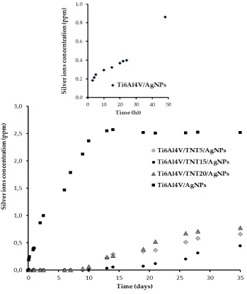
were studied for five weeks. Results of these investigations are presented in Figure 5.
277
Analysis of ICP MS data revealed that 3 hours after immersion of Ti6Al4V/AgNPs system in the PBS
278
solution, the concentration of Ag+ ions was 0.18 ppm, and after 24 and 48 hours it was 0.40 and 0.86
ppm, respectively (Figure 5; extracted graph). Over the next 12 days, a further increase in the
280
concentration of Ag+ in PBS solution was observed up to 2.52 ppm after 14 days.
281
282
Figure 5. Silver ions released from Ti6Al4V/AgNPs coatings and Ti6Al4V/TNT5/AgNPs;
283
Ti6Al4V/TNT15/AgNPs; Ti6Al4V/TNT20/AgNPs coatings immersed in phosphate buffered saline (PBS).
284
The extracted graph shows the concentration changes of silver ions released from the surface of
285
Ti6Al4V/AgNPs in the first 48 hours after immersion off the sample in PBS solution
286
During the next 14 days, the concentration of Ag+ ions did not change significantly remaining at
287
2.51-2.57 ppm (Figure 5). Studies of Ti6Al4V/TNT/AgNPs composites, which were produced by the
288
deposition of silver nanoparticles on the surface of titanium dioxide nanotubes showed, that the Ag+
289
releasing processes were proceeded in the another way (Figure 5). In our experiments we have used
290
Ti6Al4V/TNT substrates of nanotube diameters ca. 35-45 nm (TNT5), 70-80 nm (TNT15), and 100-120
291
nm (TNT20). Obtained results revealed that during the first 14 days, the release of silver ions from
292
the surface of all studied Ti6Al4V/TNT/AgNPs composites immersed in PBS solution, was not
293
observed. After this time there was a slow increase of Ag+ concentration, reaching the highest value
294
ca. 0.77 ppm (Ti6Al4V/TNT20/AgNPs) after 35 days, which was three times lower than in the case of
295
amounted ca. 0.44 ppm (after 35 days) has been noticed for Ti6Al4V/TNT15/AgNPs. The obtained
297
results revealed the clear impact of AgNPs diameter and the manner of their arrangement on the
298
surface of TNT layers on the concentration of released silver ions (Figure 4).
299
2.4. Mechanical properties of Ti6Al4V/AgNPs, Ti6Al4V/TNT, and Ti6Al4V/TNT/AgNPs
300
The studies has been carried out for Ti6Al4V/AgNPs, Ti6Al4V/TNT, and Ti6Al4V/TNT/AgNPs
301
systems, where TNT layers were produced using 5V (TNT5) and 15V (TNT15) potentials. The aim
302
was to estimate mechanical property changes of two different type of TNT coatings enriched by
303
AgNPs, i.e. the network formed from densely packed TiO2 tubes (TNT5) and the layer composed of
304
separated and ordered nanotubes (TNT15).
305
2.4.1. Surface topography
306
Surface topographies of the obtained coatings and the reference Ti alloy were examined by means of
307
atomic force microscopy (AFM, NaniteAFM, Great Britain) in the 50 x 50 μm area. Surface roughness
308
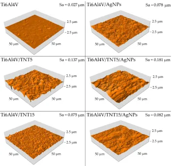
parameter Sa, was determined using software that is an integral part of the device. As demonstrated
309
by the conducted research, electrochemical anodization increases the roughness parameter Sa for
310
both coatings produced at 5 V and 15 V. For the coating obtained at a voltage of 5V, the increase in
311
the Sa parameter was almost threefold and for the coating obtained with 15V more than 5 times.
312
Also, the implantation of silver ions into electrochemically anodised coatings further increases the Sa
313
parameter. In the case of the Ti6Al4V/TNT5/AgNPs coating, the Sa parameter increased by a further
314
32% and for the Ti6Al4V/TNT15/AgNPs coating by 9.3%. The implantation of silver ions into the
315
Ti6Al4V substrate causes a threefold increase in surface roughness, from Sa = 0.027 µm to Sa = 0.078
316
µm (Figure 6).
317
318
Figure 6. AFM surface topography and Sa parameter of reference Ti6Al4V, and coating Ti6Al4V/AgNPs and
319
Ti6Al4V/TNT/AgNPs composites.
2.4.2. Hardness and Young’s modulus
321
Hardness tests were carried out using a Berkovich indenter. All tested samples were subjected to 25
322
(5 x 5) measurements of nanoindentation.Individual indentations were spaced 20 μm apart (in both
323
axes). Table 5 presents mechanical properties measured in nanoindentation tests and Figure 7
324
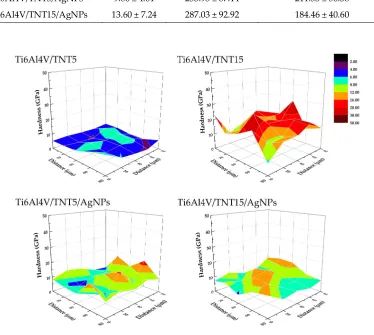
exemplary hardness distribution on the area of 50 x 50 µm. Obtained results revealed that the surface
325
implantation of the Ti6Al4V alloy with silver ions causes a slight increase in hardness from, 6.18 GPa
326
to 6.81 GPa. On the other hand, after electrochemical anodization of the titanium alloy surface, the
327
increase in hardness is greater than after surface implantation with silver ions. A particularly large,
328
more than two and a half times increase in hardness was noted for electrochemically anodized
329
coatings obtained at 15 V (Ti6Al4V/TNT15).
330
Table 5. Mechanical properties (hardness, Young’s Modulus and maximum depth of indentation) of reference
331
Ti6Al4V, Ti6Al4V/AgNPs and Ti6Al4V/TNT/AgNPs composites
332
333
334
Figure 7. Hardness distribution of Ti6Al4V/TNT5, Ti6Al4V/TNT15 and Ti6Al4V/TNT5/AgNPs,
335
Ti6Al4V/TNT15/AgNPs composites.
336
Biomaterial sample
Hardness [GPa]
Young’s Modulus [GPa]
Maximum depth of indentation [nm]
Ti6Al4V 6.18 ± 2.88 230.12 ± 21.68 162.18 ± 12.18 Ti6Al4V/AgNPs 6.81 ± 2.55 187.54 ± 54.33 253.09 ± 51.55
Ti6Al4V/TNT5 7.42 ± 3.30 229.71 ± 88.07 302.40 ± 61.85
Ti6Al4V/TNT15 16.23 ± 8.81 350.64 ± 157.57 168.11 ± 46.04
Ti6Al4V/TNT5/AgNPs 9.86 ± 4.61 253.93 ± 87.14 211.53 ± 56.38
For coating obtained at 5 V (Ti6Al4V/TNT5) increase in hardness was not so significant; the value
337
only increased by 20%. After implantation with silver ions electrochemically anodized coatings, it
338
can be noticed that depending on the anodizing voltage, the hardness either decreases or increases.
339
In the case of anodized coating obtained at 5 V, after implantation with silver ions an increase in
340
hardness by 33% (from 7.42 GPa to 9.46 GPa) is observed. However, for anodized coating obtained at
341
15 V, after implantation with silver ions, a 16% reduction in hardness is observed (from 16.23 GPa to
342
13.60 GPa). Similar changes after the silver ion implantation of anodized coatings, as in the case of
343
hardness, can also be observed for the measured Young's modulus, i.e. an increase in stiffness for the
344
Ti6Al4V/TNT5/AgNPs composite and a decrease in stiffness for the Ti6Al4V/TNT15/AgNPs
345
composite. In turn, the implantation with silver ions of the surface of the Ti6Al4V alloy results in the
346
reduction of the Young's modulus from 230.12 GPa to 187.54 GPa (18.5%).
347
2.4.3. Adhesion tests of Ti6Al4V/TNT and Ti6Al4V/TNT/AgNPs composites
348
The coatings were subjected to 5 scratch tests (individual nanosporks were spaced apart by 250
349
μm). Table 6 presents aggregate results for all investigated coatings and Figure 8 shows
350
exemplary curves obtained in the scratch test. As can be seen from the data presented in
351
Table 6, electrochemical anodization at 15 volts allows obtaining coatings with greater adhesion
352
to the substrate than anodizing at 5 volts. The critical force resulting in the loss of adhesion is
353
about 39% higher for the coating obtained at 15 volts than for the coating obtained at 5 volts.
354
Table 6. Results of nano scratch-tests of Ti6Al4V/TNT and Ti6Al4V/TNT/Ag composites
355
356
357
358
359
360
361
Figure 8. Examples of results obtained in the scratch test for Ti6Al4V/TNT5 coating and for
362
Ti6Al4V/TNT5/AgNPs composite.
363
Nano scratch – test properties
Biomaterial sample Critical Friction [mN] Critical Load [mN]
Ti6Al4V/TNT5 155.76 ± 69.02 197.713 ± 78.62
Ti6Al4V/TNT15 234.68 ± 21.05 275.03 ± 28.91
Ti6Al4V/TNT5/AgNPs 213.57 ± 49.50 275.11 ± 58.15
In addition, the standard deviation of the average results of the critical force causing the loss of
364
adhesion to the substrate is about 3 times greater in the case of coatings obtained with the
365
voltage of 5 volts. Implantation of electrochemically anodized coatings with Ag ions contributes
366
to changes in the critical force that causes loss of coating adhesion. Electrochemically anodized
367
coatings obtained at 5 V, after their implantation with Ag ions, show an increase in critical force
368
of about 39% while the implantation with Ag ions of coatings obtained at 15 V causes a slight
369
decrease in adhesion by about 3.6%.
370
3. Discussion
371
The implant samples fabricated by the selective laser sintering of Ti6Al4V powders (SLS technology)
372
were used as substrates in all our experiments, which results are discussed in this paper. The
373
appropriate porosity of substrates was obtained by covering of their surface with TiO2 nanotube
374
coatings (TNT), which were produced using the electrochemical anodization method [31-33]. In our
375
works, we have focused on studies on amorphous Ti6Al4V/TNT systems produced using potentials:
376
5V (Ti6Al4V/TNT5), 15V (Ti6Al4V/TNT15), and 20V (Ti6Al4V/TNT20), which showed the promising
377
bioactivity [32]. The conversion of amorphous TiO2 layers into anatase phase during their heating up
378
to 573 K were not noticed, which was confirmed by analysis of IR and Raman spectra. This fact was
379
important for our further works associated with the use of CVD technique in order to the enrichment
380
of the Ti6Al4V and Ti6Al4V/TNT substrate surfaces with the AgNPs. Our earlier experience with the
381
use of the different Ag(I) precursors in CVD experiments prompted us to choose Ag(O2CC2F5) as a
382
suitable source of dispersed AgNPs [28,29]. However, during the recrystallization of this compound
383
from a 1:2 EtOH/H2O mixture, the colorless crystals have been isolated after 5 days. The analysis of
384
single crystals X-ray diffraction data proved the formation of trihydrate species of the general
385
formula [Ag5(O2CC2F5)5(H2O)3] (Figure 1, Table 1). Three water molecules, which are presented in
386
the structure of this compound (differently coordinated with silver atoms and taking part in possible
387
interactions by hydrogen bonds with oxygen and fluorine atoms) should impact its properties as the
388
CVD precursor. The results of volatility studies (VT IR and MS EI) showed that the heating of this
389
compound in the range 303-503 K proceeded with its dehydration and releasing of dimeric Ag(I)
390
carboxylate species. Carried out studies exhibited that in comparison to anhydrous form, the
391
isolated trihydrate crystals are characterized by the lower vaporization temperature at the pressure
392
5·10-1 hPa. Moreover, CVD experiments proved that the deposition of dispersed AgNPs proceeded
393
with the lower deposition rate rD = 2.25-2.57 mg · min-1 at TD = 553 K (Table 3). SEM images presented
394
in Figure 4 indicated that spherical nanoparticles of silver of dimeters ca. 34-80 and 24-35 nm were
395
localized on surface of Ti6Al4V/TNT5/AgNPs and Ti6Al4V/TNT20/AgNPs coatings, respectively.
396
Simultaneously, in the case of Ti6Al4V/TNT15/AgNPs most of silver particles were localized on the
397
walls, inside of tubes. The differences mentioned above can explain the noticed differences in
398
wettability (hydrophilicity) and in the way of silver ions releasing from Ti6Al4V/TNT/AgNPs
399
composites.
400
The direct consequence of the TNT layer formation on the surface of Ti6Al4V implant is the surface
401
wettability increase with simultaneous surface free energygrowth (Table 4). Obtained results are in
402
good accordance with the previous reports [34]. The enrichment of Ti6Al4V and Ti6Al4V/TNT
403
surface by AgNPs lead to decrease of their wettability and SEP value. The analysis of water contact
404
angle changes revealed that the AgNPs deposition on the surface of hydrophilic surface of TNT
405
coatings (water contact angle < 10 deg) lead to the increase of their hydrophobicity (water contact
406
angle was changed to 110.2 - 124.2 deg) (Table 4). Simultaneously, it should be noted that
407
hydrophobicity of studied samples changes in the row: Ti6Al4V/TNT15/AgNPs >
408
Ti6Al4V/TNT5/AgNPs > Ti6Al4V/TNT20/AgNPs. The increase of hydrophobicity of TNT layers
409
(diameter 33 nm) after their decoration by AgNPs (diameter 35 nm) was also noticed by Caihong et.
410
al [35]. Insertion of an AgNPs-enriched implant into an aqueous solution is associated with the
411
oxidation of metal nanoparticles and the releasing of silver ions, which has direct impact on
412
potential antimicrobial properties of the produced coatings [36]. Figure 4 shows that Ag+ ions were
413
time, the release rate changes indicate on a saturated behavior, and the concentration of the Ag+ ions
415
in PBS was close to 2.5 ppm. The higher concentration of these ions than 10 ppm in the human body
416
can be toxic [37]. Zaho et. al. showed a similar way of Ag+ releasing from the surface of Ti/AgNPs
417
substrates, however concentration of silver ions in PBS solution after 7 days stabilized on the level
418
0.13 ppm [38]. In the case of Ti6Al4V/TNT/AgNPs coatings immersed in PBS solution, the different
419
silver ion releasing pathway has been noticed (Figure 4). Independently to the TNT diameters (TNT5
420
- 35-45 nm, TNT15 - 70-80 nm, TNT20 - 100-120 nm), the silver ions release process was not observed
421
in first 7 days. After this time, the Ag+ ions concentration slowly increases, reaching values 0.44-0.77
422
ppm after 35 days dependently to the TNT diameter, AgNPs size, and the way of their distribution.
423
Attention is drawn to the fact that the release rate of silver ions from Ti6Al4V/TNT20/AgNPs (lowest
424
value of SEP and water contact angle 110.2 deg) is higher in comparison to Ti6Al4V/TNT15/AgNPs
425
(highest value of SEP and water contact angle 124.2 deg) (Table 4). The earlier studies of
426
Ti/TNT(anatase)/AgNPs composites (tube diameters were 50, 75, and 100 nm) revealed that Ag+ ions
427
were releasing with the high rate in the first 2 days and maintaining concentration at the level
428
0.25-0.28 ppm [38]. Also in this case, the highest release rate was noticed for AgNPs deposited on the
429
surface of TNT layer consisted from tubes of diameter 100 nm. Our earlier studies of Ag+ ions
430
releasing from Ti/TNT/AgNPs composites revealed that after 21 days the concentrations of this ions
431
in PBS solution was close to 0.005-0.008 ppm and after 28 days it increased to the level 0.15-0.22 ppm
432
[33].
433
Up till now, the mechanical properties of TiO2 coatings produced by the electrochemical
434
anodization of titanium alloys has been poorly explored. However, Young’s modulus, hardness and
435
adhesion of the coating to the substrate can be the decisive factors in terms of applications, for
436
example, when considering the production of such coatings on implants elements. The strong
437
integration of an implant with the bone tissue is crucial for the safe operation of the implant. The loss
438
of coherence between the bone and the implant due to friction contributes to the implant wear. The
439
abrasive wear of the implant may additionally cause inflammatory reactions in the patient's body.
440
Von Wilmowsky et.al reported in their work [39] that TiO2 nanotube coatings have shown a “good”
441
qualitative adherence, but other reports [40,41] have qualified such coatings as “not very well
442
adherent”. Results of our nano scratch-tests revealed that the adhesion of the Ti6Al4V/TNT15
443
coating to the substrate is slightly greater than the Ti6Al4V/TNT5 coating (Table 5, Figure 8). This
444
difference can be resulted in the differences in the way of TNT coatings architecture. The TNT5 layer
445
is composed of dense packed nanotubes of diameter ca. 35-45 nm and wall thicknesses ca. 12 nm,
446
while the TNT15 consist of separated tubes of diameter ca. 70-80 nm and wall thicknesses ca. 20 nm.
447
After the AgNPs deposition on the surface of TNT5 coating, the dispersed nanoparticles with
448
diameters of 34-80 nm, were located mainly on the layer surface, which should not impact the
449
adhesion of the coating to the substrate. However, AgNPs of diameters similar to tube sizes can be
450
located inside of tubes or close them. This can explain the adhesion increase of TNT5 coating from
451
197.7 mN up to 275.03 mN after the deposition AgNPs on it's surface. In the case of TNT15 coating
452
which consists of tubes of diameters 70-80 nm (TNT15) the size of AgNPs decreased to 10-18 nm
453
maximum. The metallic grains were located inside the tubes on their walls which caused a slight
454
decrease in the adhesion of the coating to the substrate (from 275.1 mN to 267.7 mN).
455
Analysis of data presented in Table 5 revealed a clear increase of nano-mechanical properties
456
(hardness, Young’s modulus) of Ti6Al4V substrate surface after the formation Ti6Al4V/TNT system.
457
However, it should be noted that the magnitude of these changes is associated with the morphology
458
of produced TNT coatings. The results of our measurements indicate that the hardness (7.42 GPa)
459
and Young’s modulus (229.71 GPa) of Ti6Al4V/TNT5 coatings are significantly lower than that of
460
Ti6Al4V/TNT15 coatings (hardness 16.23 GPa and Young modulus 350.64 GPa), despite the fact that
461
they have a finer nanotubes structure. It can be explained by the increase of both stiffness and
462
hardness of coatings, which results from increase of the used voltage in the anodization process. The
463
earlier works revealed that voltage increase (at a constant process time) is accompanied with an
464
increase nanotubes diameter, wall thickness and also their length [42]. Moreover, the increase in
465
results in the formation of larger pores and greater distance between them [43]. As a result of these
467
processes, the nanotubes of larger diameter and wall thickness are formed. Bauer et al. [44], revealed
468
that anodizing of titanium using voltages 10-25 V led to the formation of coatings composed of
469
separated and ordered nanotubes, while the use of lower voltages led to the formation of a structure
470
resembling an ordered network. For studied coatings above mentioned effects are noticed for TNT15
471
and TNT5 respectively. The important factor which can influence the hardness and stiffness of TNT
472
coatings is the phase structure of nanotubes. Analysis of the previous reports showed that anodized
473
TiO2 nanotubes are amorphous in nature [45-47]. However, the method and parameters of coatings
474
production as well as their heat treatment may affect the occurrence of crystalline TiO2 phases such
475
as anatase, rutile or a mixture of these polycrystalline forms. It was indicated that amorphous TiO2
476
nanotubes are softer than mixture of amorphous and crystallized TiO2 (anatase) nanotubes. Also the
477
geometry of nanotubes, i.e. their length and wall thickness will affect the hardness measurement
478
result [48-50]. In addition, it is well-known that the radius of the nanoindenter's tip rounding has an
479
effect on the test results. The porosity of the coatings constitutes an additional parameter affecting
480
their hardness. Munirathinam and Neelakantan reported [51] that porosity has a significant
481
influence on the elastic modulus of the nanotubes. In our experiments, the potential of 15V applied
482
during the anodizing the Ti6Al4V alloy was low enough to the formation of a structure with low
483
porosity, as evidenced by the high hardness of the Ti6Al4V/TNT15 coating. After enriching
484
produced coatings by AgNPs, the hardness of the Ti6Al4V/TNT5 coating increased from 7.42 GPa to
485
9.86 GPa, while for the Ti6Al4V/TNT15 coating the hardness decreased from 16.23 GPa to 13.60
486
GPa. Considering that during the CVD process the structure of amorphous TNT coatings did not
487
change, the hardness increase of the Ti6Al4V/TNT5/AgNPs composite can be explained by the
488
deposition of AgNPs on the surface of an ordered network, consisted of dense packed TiO2
489
nanotubes. On the other hand, the decrease in the hardness of the Ti6Al4V/TNT15 coating after the
490
process of silver crystallite deposition can be due to the much lower hardness of silver nanoparticles
491
deposited only on the tube walls as opposed to the hardness of the separated and ordered TiO2
492
nanotubes.
493
494
4. Materials and Methods
495
496
4.1. Synthesis of silver CVD precursor and conditions CVD processes carry out
497
The silver(I) pentafluoropropionate has been synthesized according to previously reported
498
procedure [28,29]. The slow recrystallization of this salt from the 1:2 EtOH/H2O solution led to the
499
isolation of stable in air and colorless crystals after 5 days. The light sensitivity of these crystals
500
required their storage in the light protected container.
501
Yield: 89.2%; anal. calculated for C10H6F25O13Ag5: C, 8.98 %, H, 0,44 %,; Found: C, 9,09 %, H, 0,47 %.
502
13C NMR (75 MHz), δ (ppm): 59.04 (CF2), 117.49 (CF3), 167.25 (COO), 19F NMR (CDCl3, 376 MHz), δ
503
(ppm): - 82.91 (s, 3F), - 118.38 (d, J=21.1 Hz, 2F) Solid NMR spectra were recorded in a Varian Gemini
504
200 MHz NMR spectrometer in CDCl3 (Varian Inc., Palo Alto, Califirnia USA). Single crystal X-ray
505
diffraction data were collected from a crystal of dimensions 0.57 × 0.51 × 0.38 nm with an Oxford
506
Diffraction KM4 CCD diffractometer (Oxford Diffraction Ltd., Abingdon, Oxfordshire. UK)(Mo Kα
507
about wavelength λ=0,71073Å). The structure was solved by direct methods and was refined with
508
the full-matrix least squares on F2 using the software package SHELX-97 [52]. All figures were
509
prepared in DIAMOND [53] and ORTEP-3 [54]. CCDC: 1477237; contains the supplementary
510
crystallographic data for [Ag5(O2CC2F5)5(H2O)3]. These data can be obtained free of charge via
511
http://www.ccdc.cam.ac.uk/conts/retrieving.html, or from the Cambridge Crystallographic Data
512
Centre, 12 Union Road, Cambridge CB2 1EZ, UK; fax: (+44)1223-336-033; or e-mail:
513
[email protected]. Crystal data and structure refinement for this compound are given in Table
514
Table 7. Crystal data and structure refinement for [Ag5(O2CC2F5)5(H2O)3)]
519
520
Formula sum C15 H6 Ag5 F25 O13
Formula weight 1408.55
Crystal system triclinic
Space group P -1
Unit cell dimensions a = 11.3277(5) Å b = 13.0765(5) Å c = 13.7547(5) Å = 116.746(4)o
= 100.869(3)o
= 99.819(3)o
Cell volume [Å3] 1709.36(13)
Density (calculated) [Mg/m3] 2.737
Z 2
Absorption coefficient [mm-1] 3.005
F(000) 1320
Crystal size [mm] 0.57 x 0.51 x 0.38 Theta range for data collection [dego] 2.16 to 26.37
Index ranges -14<=h<=14
-16<=k<=16 -17<=l<=17
Reflections collected 18624
Reflections unique / Rint 6960 / 0.0424
Completeness to theta = 26.37 99.5%
Transmission Max/Min 0.3947 / 0.2792
Refinement method Full-matrix least-squares on F^2 Data/restraints/parameters 6960 / 20 / 592
Goodness-of-fit on F^2 1.043
Final R indices [I>2sigma(I)] R1=0.0474 wR2=0.1339 R indices (all data) R1=0.0627 wR2=0.1439 Largest diff. peak and hole [e.Å-3] 0.937 and -0.846
R1 = Fo - Fc/Fo
521
wR2 = {Σ[w(Fo2-Fc2)2]/ Σ[w(Fo2)2]}1/2
522
523
The enrichment of AgNPs on the surface of Ti6Al4V and Ti6Al4V/TNT substrates were carried out
524
using CVD method (the horizontal hot-wall reactor) under the conditions presented in Table 2 [29].
525
4.2. The production of Ti6Al4V/TNT substrates and its characteristics
526
Titanium dioxide nanotube layers (TNTs) were fabricated on the surface of implants of the radial
527
bone (total area implant - 20.53 cm2, formed by selective laser sintering (SLS) of Ti6Al4V powder) as
528
a result of the electrochemical anodic oxidation, according to the method previously described
529
[31,32,33]. This process was carried out at the following voltages: 5 V (TNT5), 15 V (TNT15) and 20 V
530
(TNT20). The anodizing time was t = 30 minutes. The morphology of the produced coatings were
531
examined using a Quanta scanning electron microscope with field emission (SEM, Quanta 3D FEG,
532
Huston USA). The structure of the produced TiO2 nanotube layers was studied using Raman
533
spectroscopy (RamanMicro 200 PerkinElmer (PerkinElmer Inc., Waltham, USA) ( = 785 nm)) and
534
diffuse reflectance infrared Fourier transform spectroscopy (DRIFT, Spectrum2000, PerkinElmer
535
Inc., Waltham, USA).
536
4.3. Measurement of the contact angle and surface free energy of biomaterials
537
Determination of the wettability was carried out by the measuring of the contact angle. The contact
538
angle was measured using a goniometer with drop shape analysis software (DSA 10 Krüss GmbH,
539
(H2O) and diiodomethane (CH2I2). In the case of distilled water, the volume of the drop in the contact
541
angle measurement was 3 μl, and in the case of diiodomethane 4 μl. In order to determine the
542
surface free energy, mathematical calculations were performed using the Owens-Wendt method.
543
Each measurement was carried out three times.
544
4.4. Evaluation of stability and durability of coating materials in the body fluid environment
545
The analysis was carried out on Ag-enriched (a) titanium foil (Ti6Al4V, gradation 5, 99.7% purity,
546
STREM) and (b) titanium foil with tiatnium dioxide nanotube modified surface (i.e. arrangements
547
Ti/Ag and Ti/TNT5/Ag; Ti/TNT15/Ag; Ti/TNT20/Ag). Both variants were cut into 7 mm x 7 mm
548
pieces. These composites were additionally protected with polyglycolide (PGA) and were also
549
analyzed. The prepared materials were immersed in 15 ml of buffered saline solution, with the
550
concentration of ions and the osmotic pressure being comparable to that which prevails in human
551
body fluids. This solution was made by dissolving a PBS tablet with the following composition: 140
552
mM NaCl, 10 mM phosphate buffer, 3mM KCl in 100 ml distilled water. The samples were kept in an
553
incubator at 37°C for 1, 2, 3, 4, 6, 7, 9, 10, 13, 14, 21, 26, 28 and 35 days. Estimation of silver
554
concentration was performed by mass spectrometry with plasma ionization inductively coupled to a
555
quadrupole analyzer using an ICP-MS 7500 CX spectrometer with Agilent Technologies collision
556
chamber (Agilent Technologies Inc., Tokyo, Japan).
557
558
4.5. Topographies and mechanical properties of the produced nanocoatings on the surface of 3D printed
559
implants
560
Surface topographies were examined by means of atomic force microscopy (AFM, NaniteAFM,
561
Nanosurf AG, Liestal, Switzerland) using a contactless module with a force of 55 mN in the 50 x 50
562
μm area. Hardness tests and Young modulus measurements were carried out using a nanoindenter
563
(NanoTest Vantage, Micro Materials Ltd., Wrexham, UK) using a pyramidal, diamond, three-sided
564
Berkovich indenter with an apical angle of 124.4 °
.
Hardness tests were performed for the loads of 10565
mN. The time of load increase from the zero value to the maximum load 10 mN was 15 s.
566
Indentation involving one cycle with 5 s dwell at maximum load. Hardness values (H), reduced
567
Young's modulus (Er) and Young's modulus were determined using the Oliver-Pharr method using
568
the NanoTest results analysis program. In order to convert the reduced Young's modulus into the
569
Young's modulus, a Poisson coefficient of 0.25 was assumed for the coatings.
570
Tests of coatings adhesion were made using nanoindenter (NanoTest Vantage, Micro Materials Ltd.,
571
Wrexham, UK) and using the Berkovich indenter, as in the case of nanoindentation tests.
572
The parameters of scratch tests were as follows: scratch load - 0 to 500 mN, loading rate – 3.3 mN/s,
573
scan velocity - 3 μm/s, scan length - 500 μm. Based on the dependence of the friction force (Ft) on the
574
normal force (Fn) in the program for the analysis of NanoTest results, the values of critical friction
575
force (Lf) and critical force (Lc) which caused separation of the layer from the substrate, were
576
determined.
577
578
5. Conclusions
579
The direct result of our works was the fabrication of coatings composed of the dispersed AgNPs
580
and/or the TNT/AgNPs nanocomposites on the surface of Ti6Al4V implants, produced in SLS
581
technology. The TNT layers were produced using electrochemical anodization of Ti6Al4V at 5, 15,
582
and 20V, while CVD method was used in order to enrich Ti6Al4V and Ti6Al4/TNT substrates by
583
silver nanoparticles. The CVD experiments carried out proved the utility of [Ag5(O2CC2F5)5(H2O)3)]
584
as a precursor of metallic silver nanoparticles. The enrichment of Ti6Al4V and Ti6Al4V/TNT
585
substrates with AgNPs increased their surface free energy, hardness, and Young’s modulus. From
586
the Ti6Al4V/TNT/AgNPs nanocomposites amorphic Ti6Al4V/TNT15/AgNPs revealed significant
587
hydrophobic properties. It showed also the best nano-mechanic properties. Studies of
588
Ti6Al4V/TNT/AgNPs composites immersed in PBS solution proved that concentration of silver ions
589
relation to previous research this result indicates that the nanocomposites produced according to
591
described in paper procedure should be not toxic to the cells of the human body.
592
593
Author Contributions: Conceptualization, P.P. and A.R.; Methodology, P.P., A.R., M.S.; Formal Analysis, A.R.,
594
M.E., M.S., T.M.M., P.P.; Investigation, A.R., T.M.M., M.G, M.E., M.B.; Writing-Original Draft Preparation, P.P.
595
Funding: this research was funded by the Regional Operational Programme of the Kuyavian-Pomeranian
596
Voivodeship (1.3.1. Support for research and development processes in academic enterprises), within the grant
597
obtained by Nano-implant Ltd.
598
Conflict of Interest: The authors declare no conflict of interest.
599
600
References
601
602
[1] Vorndran, E.; Moseke, C.; Gbureck, U. 3D printing of ceramic implants. MRS Bulletin 2015, 40, 127-136, DOI.
603
10.1557/mrs.2015.326
604
[2] lmquist, A.; Omar, O. M.; Esposito, M.; Lausmaa, J.; Thomsen, P. Titanium oral implants: surface
605
characteristics, interface biology and clinical outcome. Journal of The Royal Society Interface 2010, 7, 515-527,
606
DOI:10.1098/rsif.2010.0118.focus.
607
[3] Streckbein, P.; Streckbein, R.G.; Wilbrand, J.F.; Malik, C.Y.; Schaaf, H.; Howaldt, H.P.; Flach, M. Non-linear
608
3D Evaluation of Different Oral Implant-Abutment Connections. Journal of Dental Research 2012, 91, 1184-1189,
609
DOI:10.1177/0022034512463396.
610
[4] Dekker, T.J.; Steele, J.R.; Federer, A.E.; Hamid, K.S.; Adams, S.B. Use of Patient-Specific 3D-Printed Titanium
611
Implants for Complex Foot and Ankle Limb Salvage, Deformity Correction, and Arthrodesis Procedures. Foot &
612
Ankle International 2018, 36, 1-6, DOI:10.1177/1071100718770133.
613
[5] Tedesco, J.; Lee, B.E.J.; Lin, A.Y.W.; Binkley, D.M.; Delaney, K.H.; Kwiecien, J.M.; Grandfield, K.
614
Osseointegration of a 3D Printed Stemmed Titanium Dental Implant: A Pilot Study. International Journal of
615
Dentistry 2017, 2017, 1-11, DOI: 10.1155/2017/5920714.
616
[6] Shirazi, S.F.S.; Gharehkhani, S.; Mehrali, M.; Yarmand, H.; Metselaar, H.S.C.; Kadri, N.A.; Osman, N.A.A.
617
A review on powder-based additive manufacturing for tissue engineering: selective laser sintering and inkjet
618
3D printing. Journal Science and Technology of Advanced Materials 2015, 16, 1-20, DOI:10.1088/1468-6996/
619
16/3/033502.
620
[7] Tran, Q.H.; Nguyen, V.Q.; Le, A.T. Silver nanoparticles: synthesis, properties, toxicology, applications and
621
perspectives. Advances in Natural Sciences: Nanoscience and Nanotechnology 2013, 4, 1-20, DOI:
622
10.1088/2043-6262/4/3/033001.
623
[8] Kang, C.G.; Park, Y.B.; Choi, Oh, H.S.; Lee, K.W.; Choi, S.H.; Shim, J.S. Osseointegration of Implants
624
Surface-Treated with Various Diameters of TiO2 Nanotubes in Rabbit. Journal of Nanomaterials 2015, 2015, 1-11,
625
DOI:10.1155/2015/634650.
626
[9] Piszczek, P.; Lewandowska, Ż.; Radtke, A.; Jedrzejewski, T.; Kozak, W.; Sadowska, B.; Szubka, M.; Talik, E.;
627
Fiori, F. Biocompatibility of Titania Nanotube Coatings Enriched with Silver Nanograins by Chemical Vapor
628
Deposition. Nanomaterials 2017, 7, 1-19, DOI: 10.3390/nano7090274.
629
[10] Radtke, A.; Topolski, A.; Jędrzejewski, T.; Kozak, W.; Sadowska, B.; Więckowska-Szakiel, M.; Szubka, M.;
630
Talik, E.; Nielsen, L.P.; Piszczek, P. The Bioactivity and Photocatalytic Properties of Titania Nanotube Coatings
631
Produced with the Use of the Low-Potential Anodization of Ti6Al4V Alloy Surface., Nanomaterials, 2017, 7, 1-15,
632
DOI: 10.3390/nano7080197.
633
[11] Zhao, L.; Chu, P.K.; Zhang, Y.; Wu, Z. Antibacterial Coatings on Titanium Implants. Journal of Biomedical
634
Materials Research 2009, 91, 470–480, DOI: 10.1002/jbm.b.31463.
635
[12] Costerton, J.W.; Montanaro, L.; Arciola, C.R. Biofilm in implant infections: Its production and regulation.
636
International Journal of Artificial Organs 2005, 28, 1062-1068, DOI:10.1177/039139880502801103.
637
[13] Fürst, M.M.; Salvi, G.E.; Lang, N.P.; Persson, G.R. Bacterial colonization immediately after installation on
638
oral titanium implants. Clinical Oral Implants Research 2007, 18, 501-508, DOI:doi.org/10.1111/j.1600-0501.2007.
639
01381.x
640
[14] Fielding, G.A.; Roy, M.; Bandyopadhyay, A.; Bose, S. Antibacterial and biological characteristics of silver
641
containing and strontium doped plasma sprayed hydroxyapatite coatings. Acta Biomaterialia 2012, 8, 3144, 3152,
642
DOI:10.1016/j.actbio.2012.04.004.
![Figure 1. The scheme of the structure of [Ag5(O2CC2F5)5(H2O)3]. For clarity -C2F5 groups are omitted](https://thumb-us.123doks.com/thumbv2/123dok_us/7996277.1327807/3.595.127.471.210.449/figure-scheme-structure-ag-cc-clarity-groups-omitted.webp)
![Table 1. Selected bonds lengths [Å] and angles [º] for [Ag5(O2CC2F5)5(H2O)3] (for the clarity the Ag-Ow distances have been highlighted)](https://thumb-us.123doks.com/thumbv2/123dok_us/7996277.1327807/4.595.63.523.106.666/table-selected-bonds-lengths-angles-clarity-distances-highlighted.webp)
![Figure 2. IR spectra of [Ag5(O2CC2F5)5(H2O)3] registered at 303, 398, and 523 K.](https://thumb-us.123doks.com/thumbv2/123dok_us/7996277.1327807/5.595.90.429.158.387/figure-ir-spectra-ag-o-cc-f-registered.webp)
![Table 2. Silver(I) fragmentation ions present on the mass spectra (MS EI) of [Ag5(O2CC2F5)5(H2O)3] registered at 403 and 513 K](https://thumb-us.123doks.com/thumbv2/123dok_us/7996277.1327807/6.595.143.450.117.380/table-silver-fragmentation-ions-present-mass-spectra-registered.webp)