Article 1
An Integrated Wireless, Full-Range, Capacitive Sensor
2
System Designed for Measuring Ventricular Pressure
3
NH Sebastián1, DD Alonso2, FJ Renero-Carrillo1, Noé Villa-Villaseñor3 and W Calleja-Arriaga1* 4
1 CD-MEMS INAOE, Puebla, México; [email protected], [email protected], [email protected] 5
2 Center for Engineering and Industrial Development, CIDESI, Queretaro, México; [email protected] 6
3 Advance Technology Center, CIATEQ, San Luis Potosi, México; [email protected] 7
* Correspondence: [email protected] 8
9 10
Abstract: This paper reports the novel design of a touch mode capacitive pressure sensor 11
(TMCPS) system with a wireless approach for a full-range continuous monitoring of ventricular
12
pressure. The system consists of two modules: an implantable set and an external reading device.
13
The implantable set, restricted to a 2x2 cm2 area, consists of a TMCPS array connected with a 14
dual-layer coil, for making a reliable resonant circuit for communication with the external device.
15
The capacitive array is modelled considering the small deflection regime for achieving a dynamic
16
and full 5-300 mmHg pressure range. In this design, the two inductive-coupled modules are
17
calculated considering proper electromagnetic alignment, based on two planar coils and
18
considering the following: 13.56 MHz frequency to avoid tissue damage and three types of
19
biological tissue as core (skin, fat and muscle). The system was validated with the Comsol
20
Multiphysics and CoventorWare softwares; showing a 90% power transmission efficiency at a 3.5
21
cm distance between coils. The implantable module includes aluminum- and polyimide-based
22
devices, which allows ergonomic, robust, reproducible, and technologically feasible integrated
23
sensors. In addition, the module shows a simplified and low cost design approach based on
24
PolyMEMS INAOE® technology, featured by low-temperature processing.
25
Keywords: RF MEMS, Pressure Sensor; MEMS Resonators; Implantable BioMEMS; Flexible 26
Electronics, Touch Mode Capacitive Sensor.
27 28
1. Introduction 29
This work addresses a new alternative for measuring blood pressure, using a novel LC sensor
30
arrangement, which can overcome some restrictions that are due to the reduced implantation area
31
available at the left ventricle (LV). Some recent alternatives are still considering the pulmonary
32
artery anatomy dimensions, since it can allow a wider area for the implantation of a more powerful
33
LC radiating inductor [1], however, they are characterized by a limited pressure range [2]. Some
34
biomedical and technology details are described below.
35
Regarding sensors placed inside the human body for the measurements and wireless
36
transmission of physiological parameters, some cases were proposed since several decades ago. In
37
1967, C. Collins [3] developed a passive miniature sensor for the continuous measurement of the
38
intraocular pressure on patients with glaucoma. This device was based on a passive LC resonant
39
circuit, in which the resonant frequency was varied according to the embedded pressure
40
surrounding the device. The electromagnetic coupling of the sensor to an external loop allowed for
41
the wireless transmission, hence determining the resonant frequency of the LC sensor. Then, and
42
considering some suitable calibration, that sensor was able to read the embedding pressure. Starting
43
from that work and with the current advances in microelectronics and microelectromechanical
44
systems (MEMS), several groups began conduct research based on the same principle [4-12]. As was
45
evidenced, the available area for the LC array versus power transmission is the main issue to be
46
solved for this kind of implantable sensors, calling for technological improvements in order to meet
47
the implantation requirements.
48
Blood pressure problems are a kind of disease that chronically damages the blood vessels,
49
organs and tissues of the human body. Public information shows that at least 10% of the world
50
population suffers from these diseases, with the high blood pressure being the main cause of
51
morbidity and mortality in the world [12-15]. In the heart, the contractions of the ventricular
52
chambers, left and right, provide the force to send the blood to the human limbs, however,
53
sometimes the heart cannot provide enough force to send the blood to the whole body [2]. Thus, it is
54
desired to perform some real time pressure measurements directly inside the chambers of the heart.
55
Accordingly, a successful ventricular pressure monitoring is crucial in medical diagnosis on a series
56
of diseases such as heart failure, aortic aneurysms, strokes, arteriosclerosis and renal failure [16,17].
57
Currently, there are several blood pressure measurement systems; the most common are the
58
non-invasive devices such as air-filled blood-pressure cuffs linked to a sphygmomanometer and the
59
via auscultator sound method [18]. In addition, non-invasive blood pressure measurements lack of
60
accuracy and stability, since they are indirect measurement techniques [17]. On the other hand,
61
current invasive methods are typically used for percutaneous arterial catheter system, which
62
although are very accurate, they inhibit the free movement of the patient and might be unsafe for
63
long-term use due to complications such as trauma to arterial vessels, infection, hemorrhage and
64
difficulty in obtaining access [18-21].
65
The development of polymeric materials has represented one of the most significant tools for
66
the medical area and bioengineering research, since the use of new materials has allowed significant
67
advantages for obtaining implantable devices that can work for a long time, besides they also
68
present additional advantages, such as biocompatibility, low weight, mechanical flexibility and the
69
use of minimally invasive implantation techniques.
70
In 2006, Fonseca et al. [22] published the first flexible wireless pressure sensor for monitoring
71
abdominal aortic aneurysms. This device was fabricated using a flexible polymer and ceramics
72
which incorporated using lamination techniques, in order to implement a passive resonant circuit.
73
Although this work represents one of the first academic contributions about implanted blood
74
pressure monitors with strong consideration for biocompatibility and minimally invasive
75
functionality, the device precision showed limitations by signal drift and the distance of the
76
electromagnetic transmission.
77
In 2006 [11], began the development of a new class of implantable devices for the control of
78
aortic aneurysms and heart failure. The system was named CardioMEMSTM [23-27], and consists of 79
an implantable pressure sensor, an external communication module and an intravenous supply
80
system designed to deploy the sensor in the pulmonary artery. The battery-less 3.5×30 mm device
81
has a wireless range of about 20cm. The micromachined device was fabricated utilizing two fused
82
silica wafers, electrodeposited inductors, and fusion bonding. Once implanted, the CardioMEMSTM 83
sensor provided hemodynamic data for systolic pulmonary pressure of 15-35 mmHg, diastolic
84
pressure of 8-20 mmHg and a mean of 10-25 mmHg [26, 28]. In 2014 this system was approved by
85
FDA and according to the CHAMPION study, the use of this device in patients with heart failure
86
(HF) has allowed for a reduction of hospitalization events which improved the life quality of the
87
patients [28-29].
88
CardioMEMSTM sensor and most of the pressure sensors designed to be implanted in a place 89
near the heart, are mainly placed in the pulmonary artery (PA), since the pressure in this site can be
90
related to a series of diseases such as heart failure, pulmonary hypertension and aortic aneurysms
91
[19, 23-25]. In addition, the implantation of pressure sensors in the PA offers a series of design and
92
manufacture advantages such as reduced pressure range (0-80 mm Hg), large devices due to the size
93
of the PA (3x3 cm), and the use of techniques for minimally invasive implantation. However, the
94
pressure range measured in PA cannot be related directly to cardiac ventricular contraction and
95
relaxation event. Therefore, if a reliable ventricular pressure sensor can be fabricated and implanted,
96
new diagnostic and therapeutic possibilities could be open, because the LV is the chamber of the
97
heart responsible for pumping the oxygenated blood to the circulatory system [2, 29]. As a result, the
continuous monitoring of left ventricular pressure, could allow the control of diseases such as: heart
99
failure, hypertrophy in the LV and hypertension; additionally, this will allow the control of
100
secondary diseases such as strokes, renal failure, myocardial infarctions, disease in the coronary
101
artery and aortic aneurysms, placing the sensor permanently in the aneurysmal sac [8,
102
17,19,20-21,30-43]. Figure 1 shows a geometrical approach for the left ventricle, this section is
103
proposed for the sensor implantation, with an inner available area of 2x2 centimeters [44].
104
Figure 1. Sketch of the left ventricle [44]; showing the inner section proposed for the sensor implantation. 105
Therefore, an implantable LV pressure device that meets the following considerations is
106
required: wide range of operating pressure (5 to 300 mmHg), small size, appropriated frequency
107
bandwidth, high resolution and precision, biocompatibility and stability in hostile environments. In
108
addition, the sensor design must take into account minimally invasive techniques and anchoring
109
schemes that prevents displacements of the sensor.
110
This paper reports the novel design of a two inductive-coupled modules designed for a
111
continuous monitoring of LV pressure. The conception of the implantable capacitive array and the
112
inductive coupling link are designed for accomplish practical, accurate, and real-time wireless
113
pressure sensing. This novel design is supported by our previous work: a) A magnetically coupled
114
planar coils for wireless power transfer in intraocular pressure measurements [45]; b) An aluminum
115
based thin film technique for the fabrication of capacitive sensors [46-47], and c) The implantation of
116
an experimental LC prototype beneath the conjunctiva of a rabbit´s eye using a very simple surgery.
117
The sensors array has the capability to adjust between the conjunctiva and the cornea without an
118
aggressive invasive procedure; the LC array did not suffer rejection; tissue irritation disappears after
119
three weeks; the prototype showed good stability, and the rabbit tolerated this implant during six
120
months before its sacrifice [48]. Figure 2 shows images of this previous work. This implantable
121
sensor is still under fabrication considering a thin-film monolithic approach, defining the capacitive
122
and inductive structures in the same flexible/foldable ergonomic substrate, without the use of
123
hybrid-like connections, combining two manufacturing technologies: surface micromachining and
124
flexible electronics.
(a) (b)
Figure 2. a) Aluminum based capacitive pressure sensor fabricated over a thick polyimide substrate and capped 126
with a thin polyimide film. b) Flexible LC prototype implanted in the rabbit´s eye [45, 47-48]. 127
The fabrication process was designed according to the PolyMEMS INAOE® technology, which
128
is featured by a low-temperature processing, considering materials for assuring biocompatibility.
129
Finally, this sensor can also be adapted for monitoring the pressure in different organs, such as the
130
aorta, pulmonary artery and even the urinary bladder.
131
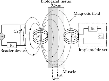
2. Integrated Wireless System Description 132
The concept supporting the wireless ventricular pressure sensor, in a passive electrical sensing
133
scheme, is shown in Figure 3. The complete monitoring system consists of two modules: an
134
implantable sensor set and an external reader device. In this design, the two inductive-coupled
135
modules are calculated considering a proper electromagnetic alignment, based on two circular
136
planar coils with the proper resonant frequency, calculated as [49-51]:
137
f= 1
2π√LC if R
2≫L
C (1)
Where L, C and R denotes the magnitudes for inductance, capacitance and resistance,
138
respectively. In addition, for this design both coupled modules are modelled as a multicore
139
transformer for transmission/reception power. That is, when a time varying current circulates
140
though the coil (Lr) from the reader device, an electromagnetic field is radiated around it. If the coil 141
(Ls) from the implantable set is inside the radiation zone, some electromagnetic field lines cross the 142
Ls area, generating a time varying current on the implantable set and operates according to the Cs 143
magnitude. Cs will vary following the ventricular pressure, and the proper electromagnetic coupling 144
is the main subject for this work.
145
146
Figure 3. Electromagnetic scheme for the wireless ventricular pressure sensor. 147
The resonant frequency of the implanted sensor set and the signal coupling towards the
148
external coil can be modeled as a two-port network. Under this premise, the input impedance of the
149
reader coil is expressed taking electrical parameters from the implantable device [49-50, 52], as
150
follows:
151
Zeq=Vr
Ir =j2πfLr 1+k
2 (f/fs)2
1-(f/fs)2+(1/Qs)j(f/fs) (2)
Where V and I are the exciting voltage and current across the reader coil, f is the excitation
152
frequency of the implanted sensor set and Q=(2πfsLs)/Rs is the quality factor of the sensor under 154
resonance.
155
It can be seen from Equation 2, that in order to change the impedance Zeq from de reader coil, 156
one must change either the k or fs of the implanted set. For ventricular pressure applications, the 157
distance between both coils will remain constant so the k will not change. Therefore, fs is the only 158
parameter capable of changing the equivalent impedance. According to Equation 1, the overall
159
variation of the capacitance into the implanted sensor array is caused by a local change of the
160
pressure, which accordingly changes the resonant frequency. Such changes are detected in the
161
reading coil as variations in the equivalent impedance, and hence related to the ventricular pressure.
162
2.1 Implantable LC sensor set 163
The implantable sensor set, restricted to a 2x2 cm2 area (according to the LV internal 164
dimensions), was defined over a 20 µm-thick polyimide film and interconnected according to Figure
165
1. It consists of 2 touch-mode capacitive pressure sensor (TMCPS) parallel array connected to a
166
dual-layer planar coil, thus a reliable resonant circuit for communication with the external device is
167
attained. The implantable set has been designed considering a thin-film monolithic approach,
168
underlying the capacitive and inductive structures in the same flexible ergonomic substrate without
169
the use of hybrid-like connections, combining two manufacturing technologies, such as surface
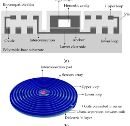
170
micromachining and flexible electronics. Figure 4 shows a 3D view of the double-layer coil and a
171
cross-section view of the implantable sensor set.
172
(a)
(b)
Figure 4. a) Cross section cut of the implantable sensor set and b) A 3D view. 173
The proposed novel capacitive array is shown in Figure 5a, it consists of a sectioned hermetic
174
chamber with 2 parallel capacitors array. In this approach, both plates are isolated by a double
175
insulator: air/silicon oxide, allowing a dynamic variable capacitive sensor [47, 53-55], as can be seen
176
in the layout of Figure 5b. The 555 µm-side capacitor is mechanically designed for response under
177
the lower LV pressure regime and the 300 µm-side capacitor is designed to obtain a response under
178
the higher LV pressure regime. This capacitive array is fully designed considering a thin polyimide
179
film, which is added as a biocompatible capping film, i. e., at the same time is part of the diaphragm
180
of the capacitors. Finally, the capacitors are analyzed as follows: a) the top diaphragm is calculated
181
to provide a direct contact with the physiological environment; thus, the structures are properly
covered with a biocompatible film; b) the double-film squared diaphragm (polyimide over
183
aluminum) was structurally modeled considering the small deflection regime [54-55]. This analytical
184
work has concluded with 2 precise mechanical complementary capacitors, capable of achieving a
185
dynamic and full 5 - 300 mmHg pressure range to cover the full diastolic-systolic pressure range
186
developed across the LV [2, 19].
187
(a)
(b)
Figure 5. a) Double diaphragm capacitive array, the sketch shows structural materials and dimensions. b) 188
Layout. 189
The detection principle for the capacitive array is based on the relationship between the changes
190
in capacitance under the applied pressure [8, 47, 49, 54]. In this case the total capacitance, at any time,
191
is the sum of the individual capacitances associated at a given pressure, as follows:
192
Cs=ε0εaireεd1Atouch1 Wmax1+εd1Wmax1+
ε0εaireεd2A
touch2
Wmax2+εd2Wmax2 (3)
Where εd is the dielectric constant of the insulating material, ATouch is the contact area of the 193
diaphragm, Wmax is the separation distance between the parallel metal plates and the subscripts 1 194
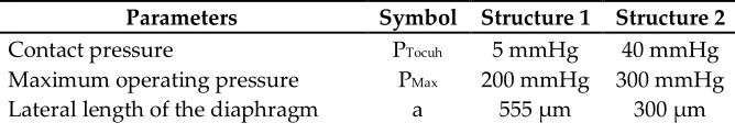
and 2 indicate the first and second capacitive structure, respectively. Table 1 shows the main
195
parametric design and the analytical results for the capacitive array. Both diaphragms were
196
calculated to operate simultaneously based on the minimum and maximum operating pressure of
197
the LV, that is, the first structure operates from the minimum pressure of 5 mmHg and the second
198
one operates up to a maximum pressure of 300 mmHg, thereby ensuring that the capacitive
199
assembly covers the full range for the ventricular pressure.
200
Table 1. Parameters design and analytical results for the capacitive array. 201
Parameters Symbol Structure 1 Structure 2
Contact pressure PTocuh 5 mmHg 40 mmHg
Maximum operating pressure PMax 200 mmHg 300 mmHg
Thickness of the lower electrode tElow 2 µm 2 µm
Thickness of the top electrode tEtop 1 µm 1 µm
Thickness of the biocompatible film tBio 1.5 µm 1.5 um
Air gap Wmax 1.5 µm 1.5 µm
Oxide thickness toxi 0.2 µm 0.2 µm
Sensor capacitance at zero pressure Cp0 1.9 pF 0.51 pF
Because the restricted area existing inside the LV, the design of the internal coil consists of a
202
dual-layer planar inductor to increase the total value of the inductance and its quality factor. The
203
two superposed aluminum loops, insolated by a dielectric bi-layer (oxide and polyimide), are
204
connected in series and composed by 28 turns each, covering an external diameter of 2cm. Regarding
205
the metal and coil thickness, they were chosen based on the full implantable set to facilitate the
206
thin-film monolithic approach. As shown in the layout of Figure 6, the full array is covered by a thin
207
polyimide film.
208
209
Figure 6. Double layer internal coil, layout showing the 5-level design. 210
The electrical characteristics of the dual-layer planar coil can be determined by using
211
established models [56-58], where the electrical inductance for a circular multi-layer coil is calculated
212
as:
213
L≅L1+L2±2M (4)
Where M=k(L1∙L2)1/2 is the mutual inductance between the two levels of the planar coil [28], 214
k=(R2out.T∙R2out.R)/(R2out.T∙R2out.R)1/2(R2out.T+X2)3/2 is the coupling factor between two coils, whereas L1 and 215
L2 are the self-inductances for the lower and upper loops, which are determined from the following 216
Equation [49-50, 57, 59]:
217
L1=L2≅µ0n
2d avgC1
2 ln
C2
F +C3F+C4F
2 (5)
Where n=(Rout - Rin)(w+s) is the number of turns of the inductor, davg=(Dout+Din)/2 is the
218
averaged diameter of the windings, F=(Dout-Din)/ Dout+Din) is the fill factor of the windings and
219
C1 – C4 are constant coefficients determined by the winding geometry [57].
220
From Equation 4 we can observe that for a multi-layer system, the final inductance increases
221
according to a positive effective mutual coupling. Figure 6 shows the layout of the sensor set. This
222
design has several advantages that include small size, stability, ergonomic and mechanical
223
flexibility. Additionally, the distribution of the windings are not superposed, in this way there is no
224
contribution to parasitic capacitance and the mutual coupling results positive.
225
The external coil was calculated under flexible conditions taking into account the physical
227
dimensions and materials for manufacturing; it was projected on a 4-layer PCB FR-4 as the substrate
228
material; composed by 27-turns cooper coil and 8-cm outside diameter, and designed following the
229
Finkenzeller condition, according the following Equations [52, 59]:
230
Dout.T≤D2√2 (6)
Rout.T≥ X2+Rout.R2 (7)
Where Dout.T=2Rout.T is the outer diameter of the outer coil, D is the radiation distance and X is the 231
separation between the inner and outer coils.
232
The electromagnetic coupling was calculated considering the following: a) 13.56 MHz
233
frequency to avoid tissue damage by radiation and heating (according to ISO 14117 for implantable
234
devices) and b) in order to simulate a more realistic environment, the core considers three
235
components for the biological tissue: the first layer is skin with 0.5 cm thickness, the second layer is
236
fat with 1 cm thickness and the third layer is muscle with 2cm thickness. Design parameters such as
237
the number of turns, width, thickness and value for the inductive element are determined based on
238
the self-inductance value of the implantable sensor set, so that the two RCL circuits resonate at the
239
same frequency. Figure 7 shows the lay out of the external coil.
240
241
Figure 7. Layout generated for the external coil. 242
The self-inductance of the external coil as well as for the internal coil were calculated based on
243
the number of turns taken from Equation 5. For the inductive coupling link, the electrical parameters
244
were calculated using well known methods [51, 59-60], and then the power transmission efficiency
245
for the inductive link is given by:
246
ƞ= k
2Q 1Q2
3R 2Rload
k2Q1Q23R2Rload+k2Q1Q2Rload2 +Q2 4R
2
2+2Q
2 2R
2Rload+Rload2
(8)
Where Q=(1/R)(L/C)1/2 represents the quality factor for the external and internal coils, R2 is the 247
equivalent resistance of the internal coil, Rload≥2ωL2 is the load resistance [59], and for this case Rload=3 248
kΩ. Table 2 shows the main parametric design and the analytical results for the internal and external
249
coils.
250
Table 2. Analytical and design parameters for the internal and external coils. 251
Quantity Symbol Internal coil External coil
Internal diameter Din 2 mm 2 mm
External diameter Dout 2 cm 8 cm
Width of the metal lines w 160 µm 700 µm
Thickness of the metal lines h 2 µm y 1 µm 35 µm
Number of turns N 28 each loop 27
Length l 1.14 m 1.7 m
Frequency of operation fs 13.56 MHz
Self-Inductance L 20.05 µH 21.29 µH
Electrical resistance R 309 Ω 4 Ω
Quality factor Q 8 591
Load resistance Rload 3 kΩ ---
Radiation distance X 3.5 cm
Coupling coefficient k 0.054
Mutual inductance M 2.5 µH
Power transmission efficiency η 90%
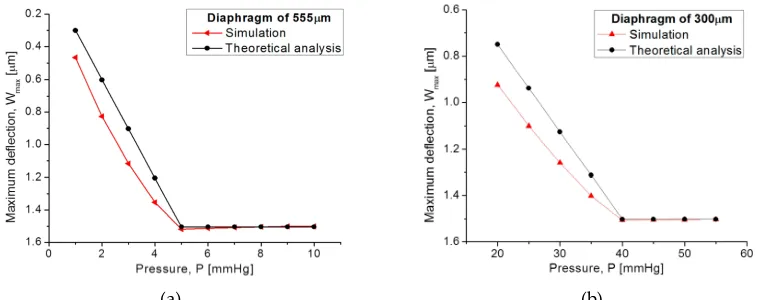
3. Results and Discussion 252
3.1. Capacitive array 253
The capacitive array was analyzed using the CoventorWare® software based on the finite
254
element method to evaluate the mechanical deformation of both diaphragms. In addition, the
255
obtained parameters (strain, stress, electrical resistance, and finally the C-P characteristics) and the
256
resultant quantitative curves were used as a design tool to achieve a desired electromechanical
257
performance. Figure 8a compares both, the analytical and simulated diaphragm maximum
258
deflection P-Wmax versus the applied pressure, obtained from the designed squared capacitive 259
structures: 555 µm- and 300 µm-side. Figure 8b illustrates the initial touching operation pressure
260
(PTouch) for each diaphragm. 261
262
(a) (b)
Figure 8. Comparison of analytical and simulated P-Wmax curves obtained from (a) 555 µm-side 263
diaphragm and (b) 300 µm-side diaphragm. 264
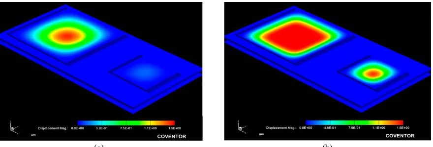
Figure 9 allows the 3D qualitative visualization for the mechanical response under an applied
265
pressure. It can be observed that the large structure operates at the low pressure regime and the
266
small one operates at the high pressure regime.
(a) (b)
Figure 9. Simulated mechanical response, obtained from the capacitive array at (a) 10 mmHg and (b) 100 268
mmHg applied pressure. 269
From Figure 8, the analytical model agrees well the calculated mechanical response, where the
270
maximum deflection (touching pressure) occurs at 5 mmHg and 40 mmHg, according to the size for
271
each squared diaphragm. The slight variation observed at the beginning of the P-Wmax curves are 272
due the fact that the analytical calculations neglects some deformations at the middle plane of the
273
composed diaphragm, and the simulation software recreates the complete trajectory of the
274
diaphragm, considering key structural parameters and a more complex analysis.
275
Once the capacitance (TCMPS) parameters have been determined for achieving an optimum
276
performance, the maximum operating pressure is evaluated according to the increasing pressure
277
over the diaphragms, hence simulating the touching contact area (Acontact) over the isolated lower 278
plate. Therefore, once the contact area does not increase anymore, the applied pressure at this point
279
is the maximum operating pressure. Figure 10 shows the P-Acontact graphs, where the maximum 280
operating pressure for each capacitive structure are plotted.The lower pressure regime corresponds
281
to the 550 µm diaphragm, and the higher pressure regime is for the 300 µm diaphragm.
282
283
Figure 10. P-Acontact graphs for the capacitive (TMCPS) sensor array. 284
In both diaphragms under increasing pressure regime, the variations of the touching contact
285
area seem slight, however these variations are enough to produce significative changes in the overall
286
capacitance, and consequently produce changes in the resonant frequency of the RCL circuit (see
287
Equation 1). The touch contact area can be expressed as ATouch=K1P-K2P2, where K1 y K2 are linear and 288
saturation constants, respectively, and K1>>K2 [53]. Therefore, under a determined pressure, the 289
contact area is proportional to the pressure, and the corresponding capacitance is directly
290
determined. This is because the overall response is a linear C–P relationship, typical of a touch mode
291
capacitive pressure sensor, which is very suitable for conditioning circuits. Figure 11 shows the
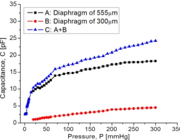
292
characteristic C–P curves obtained for each one and the full set of capacitive sensors as well.
294
Figure 11. Capacitance response versus applied pressure, covering a full 5-300 mmHg range. 295
In Figure 11, graph C, it can be seen that at the beginning the capacitance increases suddenly
296
because the 555 µm diaphragm quickly makes contact over the lower electrode. In the 15 – 75 mmHg
297
range, the capacitance increases with a linear rate typical for the 555 µm diaphragm. Around 80 - 300
298
mmHg, the capacitance increases linearly and steadily, influenced by the 300 µm diaphragm
299
according to the simulation routines. This electromechanical response from the capacitive sensor set
300
is analyzed once it is interconnected with the planar coil. As expected, the capacitance variations
301
lead to changes over the resonant frequency. Figure 12 shows the simulated operating frequency
302
versus the capacitance variations, according to the circuit shown in Figure 3.
303
304
Figure 12. Simulated operating frequency as a function of capacitance for the implantable set. 305
According to simulations, the operating frequency for the implantable sensor set has a variation
306
from 13.56 MHz to 5.2 MHz, this frequency range which is included within the industrial, medical
307
and scientific band (ISM), and completely ensures the safety because no tissue damage by radiation
308
can occur. Another key parameter for analyzing the capacitive pressure sensor is the sensitivity
309
ΔC/ΔP as a function of frequency.
310
Our mathematical analysis and simulations make evident some changes in the sensor
311
sensitivity, considering the operating frequency range. Figure 13 shows the relationship between the
312
sensitivity and the applied pressure, considering each capacitive structure. As observed, the
313
sensitivity decreases when the applied pressure increases. This sensitivity is influencing the final
314
power transmission efficiency to be discussed later.
316
Figure 11. Sensitivity versus applied pressure. 317
3.2. Inductive coupling link 318
The overall inductive coupling link was modeled considering three main factors (internal
319
dual-layer coil, external coil and protocol coupling link), using the Comsol Multiphysics® software
320
based on physical interfaces and finite element analysis. Each factor was modeled explicitly and
321
with a homogenized approach for obtaining diverse parameters, such as: self-inductance (L), mutual
322
inductance (M), electrical resistance (R), magnetic flux density (Φ) and induced current (i).
323
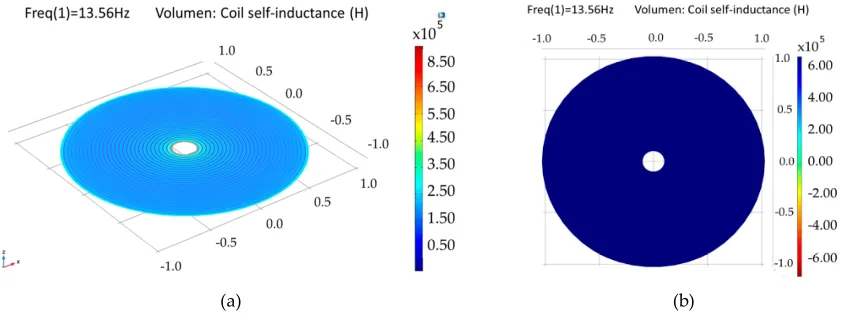
3.2.1. Internal dual-layer coil model
324
The internal dual-layer coil is simulated by parts and as a single-element, because a multilevel
325
coil involves more coupling factors, than a single-layer coil (see Equation 4). As a
326
composed-element, a self-inductance of 6.68 µH was obtained for each loop, and an electric
327
resistance of 77 Ω and 158 Ω were obtained for the lower and upper loop, respectively. For the
328
single-element coil, separated 1.5 µm by a dielectric material (polyimide) and planarly oriented, a
329
coupling factor of 0.99, a self-inductance of 27.1 µH and an electrical resistance of 259 Ω were
330
obtained, this is shown in Figure 14.
331
(a) (b)
Figure 14. Simulation results for the internal double-level coil. (a) Self-inductance for the composed 332
double coil and (b) self-inductance for a single-element coil. 333
The model for a dual-layer planar coil implemented in the implantable set, allows for obtaining
334
higher values of inductance in a small area (restricted by the anatomical dimension of the LV, which
335
results in better characteristics in terms of the internal coupling factor and power transmission
336
efficiency. Table 3 shows the simulation results for the internal coil.
Table 3. Simulation results for the internal dual coil. 340
Parameters Lower loop Upper loop Binding
Electrical resistance 77 Ω 158 Ω 259 Ω
Self-inductance 6.68 µH 6.68 µH 21.12 µH
Quality Factor 17 8.3 9.1
Internal coupling factor1 0.99
Internal mutual inductance1 6.67 µH
1Parameters between the lower and upper loops.
341
3.3.2. External coil
342
The external coil was simulated in a similar way to the internal coil, however, a less complex
343
system was considered, since the coil is formed by a single loop, thus only the explicit simulation
344
model was used. A self-inductance of 19.7 µH, a quality factor of 512 and an electrical resistance of
345
5.6 Ω were obtained.
346
3.3.3 Magnetic Coupling link model
347
The mathematical analysis of the inductive coupling link was validate with the software
348
Comsol Multiphysics based on the near field approximation. The simulation model considers that
349
the external coil is located outside the human body but establishes communication across the surface
350
skin, where the internal coil is mounted within the left ventricle at a depth of 3.5 cm. In addition, we
351
are considering a 13.56 MHz resonance frequency to avoid tissue damage by radiation and heating
352
(according to ISO 14117 for implantable devices), and in order to simulate a more realistic coupling
353
environment, the core considers three types of biological tissue: skin, fat and muscle, as shown in
354
Figure 15. Table 4 shows the parameters used for the composed biological tissue [61-62].
355
356
Figure 15. Inductive coupling link across biological tissue. 357
Table 4. Constitutive parameters of human biological tissue at a frequency of 13.53 MHz. 358
Model Thickness [cm]
Conductivity [sm-1]
Relative permittivity
Wavelength [m]
Dry skin
0.5 0.23802 285.25 2.26
Wet skin 0.38421 177.13 2.87
Fat 1 0.030354 11.827 11.11
Muscle 2 0.62818 138.44 3.24
For medical applications, a key factor is the inductive coupling link because part of the field
359
dissipates in the tissue causing some power dissipation. It is clear that as the distance between the
coils decreases, the electromagnetic field density increases, as well as other parameters such as: the
361
mutual inductance, induced current/voltage and power transmission efficiency. Figure 16 shows the
362
magnetic field density of the inductive coupling link and the relationship between the separation
363
distance between the coils and the induced voltage for an input voltage of 5 V, 10 V and 15 V.
364
(a) (b)
Figure 16. (a) Magnetic flux density and (b) induced voltage changes as a function of the separation distance. 365
Finally, the simulation results for the coupling across biological tissue delivers the following
366
results: first, they show a 90% power transmission efficiency under the lower pressure range;
367
second, under the higher pressure range the efficiency decreases to 78%. This controlled coupling
368
attenuation comes from the smooth capacitance transition over the TMCPS array; Figure 17 shows
369
this relationship.
370
371
Figure 17. Power transmission efficiency versus frequency. 372
Table 5 list the simulation parameters about the inductive coupling link, which are in good
373
agreement with the theoretical analysis.
374
Table 5. Simulation parameters for the inductive coupling link. 375
Parameters Symbol Value
Resonance frequency 13.56 MHz
Mutual inductance 3.38 µH
Magnetic flux density ∅ 150 µT
Coupling efficiency 0.054
Radiation distance 3.5 cm
Power transmission efficiency ɳ 90.7%
5. Conclusions 377
We report a new sensor scheme offering a continuous blood ventricular pressure monitor,
378
which will allow for the continuous control of some diseases such as heart failure, aortic aneurysms
379
and hypertension. The novel implantable sensor set, composed by capacitive and inductive
380
structures, are arranged over the same flexible substrate, avoiding hybrid-like connections, and
381
combining both manufacturing technologies, surface micromachining and flexible electronics. The
382
capacitive sensors array was designed using a composed aluminum/polyimide diaphragm, where
383
the structure and its parallel interconnection, are arranged in order to cover the wide LV pressure
384
range, which is a key contribution of this work. According to the anatomy of the LV, an internal
385
dual-layer coil was implemented to increase the L and Q parameters in a reduced physical area. The
386
model for a dual-layer planar coil allows for obtaining better characteristics in terms of the internal
387
coupling factor and power transmission efficiency. The implantable set presented the following
388
figures of merit: a dynamic and full 5 mmHg – 300 mmHg pressure range; and an operating
389
frequency range of 5.2–13.56 MHz. This system complies with the full diastolic-systolic pressure
390
range developed across the LV, also following the ISO 14117 standard for implantable devices and
391
the industrial, medical and scientific band (ISM). Currently the fully integrated process fabrication is
392
under progress.
393
The electromagnetic coupling across the biological tissue was validated with the Comsol
394
Multiphysics software: in the first place showed a 90% power transmission efficiency, at 3.5 cm
395
separation between coils, under the lower pressure range; second, under the higher pressure range
396
the efficiency decreases to 78%. Concerning the module fabrication, and according to our previous
397
experimental work, we adapted the PolyMEMS INAOE® technology, for an aluminum-based
398
technique, which allows for obtaining ergonomic, robust, reproducible, low-cost, and
399
technologically feasible inductive and capacitive structures. The polyimide substrate and coating
400
contribute for reducing the tissue damage and also offers a minimally invasive implantation
401
procedure. Finally, this sensor can also be adapted for monitoring the pressure in different organs
402
such as the aorta, pulmonary artery and the urinary bladder.
403 404
Acknowledgments: Natiely Hernandez Sebastián acknowledges Conacyt program scholarship #549792. 405
Author Contributions: Formal analysis Noe Villa-Villaseñor; Investigation, Natiely
406
Hernández-Sebastián, Daniela Díaz-Alonso and Francisco-Javier Renero-Carrillo, and Wilfrido
407
Calleja-Arriaga. NH Sebastián is a Ph.D. student.
408
Conflicts of Interest: “The authors declare no conflict of interest." 409
“The founding sponsors had no role in the design of the study; in the collection, analyses, or interpretation of 410
data; in the writing of the manuscript, and in the decision to publish the results”. 411
References 412
1. Yujia, P.; Tengxing, W.; Wein, J.; Xinchuan, L.; Xuejun, W. Modeling and Optimization of Inductively 413
Coupled Wireless Bio-Pressure Sensor System Using the Design of Experiments (DOE) Method. IEEE 414
Transactions on Components, Packaging and Manufacturing Technology, October 2017, Vol. 8, pp. 65-72.
415
2. Guyton, A.C.; Hall J. Textbook of medical physiology. 4th ed., 1032pp. Philadelphia-London-Toronto: 416
Saunders 1971. 417
3. Collins C. Miniature passive pressure transensors for implanting in the eye. IEEE Trans Biomed Eng. 418
1967; Vol. 14, pp. 74–83.
419
4. Rosengren, L.; Rangsten, P.; Bäcklund, Y.; Hok, B.; Svedbergh, B.; Selen, G. A system for passive 420
implantable pressure sensors. Proc. 8th Int. Conf. Solid-State Sensors and Actuators, Yokohama, Japan, 421
1993, pp. 588-591.
422
5. Olsen, E. R. et al. Intracranial pressure measurement with a miniature passive implanted pressure 423
6. Wise, K.D.; Clark, S.K. Diaphragm formation and pressure sensitivity in batch-fabricated silicon 425
pressure sensors. IEDM Tech. Dig., 1978, pp. 96-99. 426
7. Lee, Y.S.; Wise, K.D. A batch-fabricated silicon capacitive pressure transducer with low temperature 427
sensitivity. IEEE Trans. Electron Devices, 1982, vol. ED-29, no. 1, pp. 42-48. 428
8. Chatzandroulis, S.; Tsoukalas, D.; Neukomm, P.A. A miniature pressure system with a capacitive 429
sensor and a passive telemetry link for use in implantable applications. J. Microelectromech. Syst. 2000, 430
vol. 9, no. 1, pp. 18-23.
431
9. Park, E.C.; Yoon, J.B.; Yoon, E. Hermetically sealed inductor–capacitor (LC) resonator for remote 432
pressure monitoring. Jpn. J. Appl. Phys. 1998, Vol. 37, pp. 7124-7128. 433
10. Takahata, K.; DeHennis, A.; Wise K.D.; Gianchandani Y.B. A wireless microsensor for monitoring 434
flow and pressure in a blood vessel utilizing a dual-inductor antenna stent and two pressure sensors. 435
Int. Conf. Micro Electro Mechanical Systems, 2004, Vol. 17, pp. 216-9.
436
11. DeHennis, A.; Wise, K.D. A fully-integrated multisite pressure sensor for wireless arterial flow 437
characterization. Dig. North American Sensor Actuator Microsystems Workshop, 2004, Vol. 15, pp. 168-171. 438
12. Información General sobre Hipertensión en el Mundo. Available online. 439
http://apps.who.int/iris/bitstream/handle/10665/87679/WHO_DCO_WHD_2013.2_spa.pdf;jsessionid= 440
CA28E7F834B1972192D25482E211BCBC?sequence=1 (Accessed on 15 March 2018). 441
13. Banegas, J.R.; Ruilope, L.M. Mortality study from the Spanish Registry of ABPM. An appeal for the 442
transition of ABPM to clinical practice. Hipertensión y riesgo cardiovascular, September 2018, pp.97-100. 443
14. Campos, C.N.; Lucia, H.C. Hipertensión en adultos mexicanos: prevalencia, diagnóstico y tipo de 444
tratamiento. Salud pública de México, vol. 6, mayo 2018. 445
15. Maria, T.L. Burden of hypertension as a cardiovascular risk factor. Revista médica clínica los condes, 446
Marzo 2015, Vol. 26, pp. 156-163.
447
16. Lanzarini, L.; Fontana, A.; Campana, C.; Klersy, C. Two simple echo-Doppler measurements can 448
accurately identify pulmonary hypertension in the large majority of patients with chronic heart 449
failure. J Heart Lung Transplant. 2005, Vol. 24, pp. 745–754. 450
17. Hugo, E.V.; Pablo, F.C.; Roberto, A.F.; Mario, A.A.; Milton, E.A.; Carlos, C.D.; Robert, C.B. 451
Comparison of a Radiofrequency-Based Wireless Pressure Sensor to Swan-Ganz Catheter and 452
Echocardiography for Ambulatory Assessment of Pulmonary Artery Pressure in Heart Failure. 453
Journal of the American College of Cardiology. Dec 2007, Vol. 50 (25), pp. 2375-2382; DOI:
454
10.1016/j.jacc.2007.06.061. 455
18. Ogedegbe, G.; Pickering, T. Principles and Techniques of Blood Pressure Measurement. Cardiology 456
Clinics, 2010, Vol. 28, pp.571-586.
457
19. Fonarow, G.C.; Stevenson, L.W.; Walden, J.A.; et al. Impact of comprehensive heart failure 458
management program on hospital readmission and functional status of patients with advanced heart 459
failure. J Am Coll Cardiol, 1997, Vol. 30, pp. 725–732. 460
20. Fonarow, G.C.; Chelimsky-Fallik, C.; Stevenson, L.W.; et al. Effect of direct vasodilation with 461
hydralazine versus angiotensin-converting enzyme inhibition with captopril on mortality in 462
advanced heart failure: The HyC trial. J Am Coll Cardiol. 1992, Vol. 19, pp. 842–850. 463
21. Stevenson, L.W.; Tillish, T.H. Maintenance of cardiac output with normal filling pressures in patients 464
with dilated heart failure. 1986, Vol. 74, pp. 1303–1308 465
22. Fonseca, M.A.; Allen, M.G.; Kroh, J.; White, J. Flexible wireless passive pressure sensors for 466
biomedical applications. Proc. 12th Solid-State Sens. Actuators Microsyst. Workshop, 2006, pp. 37-42. 467
23. CardioMEMSTM. Available online. https://www.accessdata.fda.gov/cdrh_docs/pdf10/p100045c.pdf 468
(Accessed on 21 February 2018). 469
24. Clausen, I.; Glott, T. Development of Clinically Relevant Implantable Pressure Sensors: Perspectives 470
and Challenges. Sensors, 2014, pp. 17686–17702.
471
25. CardioMEMS, CardioMEMS, inc. announces FDA clearance of the EndoSureä wireless AAA pressure 472
measurement system for measuring intrasac pressure during thoracic aortic aneurysm (TAA) repair. 473
Available Online. http://www.cardiomems.com/content.asp?display=news&view=9 (Accessed on 21 474
on February 2018). 475
26. Host, J.F.; Hasan A. Role of telephone monitoring in patients with chronic heart failure: theory and 476
27. Pandey, A.C. et al. Reducing Days in the Hospital with Cardiomems Device in Patients with Left 478
Ventricular Assist Device. The Journal of Heart and Lung Transplantation, Vol. 37, Issue 4, pp. S280 - S281. 479
28. Rodrigo, B. Revolucionando el tratameinto de la insuficiencia cardíaca descubriendo 480
CardioMEMSTM: Descubriendo CardoMEMST. Insuficiencia cardíaca, 2015, Vol. 10(3), pp. 141-148. 481
29. Abraham, W.T.; Stevenson, L.W.; Bourge, R.C.; Lindenfeld, J.A.; Bauman J.G.; Adamson, P.B. 482
CHAMPION Trial Study Group. Sustained efficacy of pulmonary artery pressure to guide adjustment 483
of chronic heart failure therapy: complete follow-up results from the CHAMPION randomised trial. 484
Lancet, 2016, Vol. 387, pp. 453–461. DOI: 10.1016/S0140-6736(15)00723-0.
485
30. Ahmed, D. RVSP – Right Ventricular Systolic Pressure: MyHeart. Available online. 486
https://myheart.net/articles/rvsp-right-ventricular-systolic-pressure/ (Accessed on February 2018). 487
31. Takahata, K.; DeHennis, A.; Wise, K.D.; Gianchandani, Y.B. A micromachined antenna stent for 488
wireless monitoring of implantable microsensors. Proc. Annu. Int. Conf. IEEE Eng. Med. Biol. Soc. 4, 489
2004, pp. 3360–3363.
490
32. DeHennis, A.D.; Wise, K.D. A fully integrated multisite pressure sensor for wireless arterial flow 491
characterization. J. Microelectromech. Syst. 15, 2006, pp. 678–685. 492
33. CardioMEMS. Available Online. http://www.cardiomems.com (Accessed in 2018). 493
34. Allen, M.G. Micromachined endovascularly-implantable wireless aneurysm pressure sensors: from 494
concept to clinic Transducers, 2005, pp. 275–278. 495
35. Hamilton, M.A.; Stevenson, L.W.; Child, J.S.: Moriguchi, J.D.; Walden, J.; Woo, M. Sustained reduction 496
in valvular regurgitation and atrial volumes with tailored vasodilator therapy in advanced congestive 497
heart failure secondary to dilated (ischemic or idiopathic) cardiomyopathy. Am J Cardiol, 1991, Vol. 67, 498
pp. 259–263. 499
36. Harvey, S.; Stevens, K.; Harrison, D.; et al. An evaluation of the clinical and cost-effectiveness of 500
pulmonary artery catheters in patient management in intensive care: a systematic review and a 501
randomized controlled trial. Health Technol. 2006, Vol. 10, pp. 1–150. 502
37. Merchant, F.M.; Dec, G.W.; Singh, J.P. Implantable sensors for heart failure. Circ Arrhythm 503
Electrophysiol. 2010, Vol. 3, pp. 657-667.
504
38. Adamson, P.B.; Magalski, A; Braunschweig, F.; Bohm, M.; Reynolds, D.; Steinhaus, D.; Luby, A.; 505
Linde, C.; Ryden, L.; Cremers, B.; Takle, T.; Bennett, T. Ongoing right ventricular hemodynamics in 506
heart failure: clinical value of measurements derived from an implantable monitoring system. J Am 507
Coll Cardiol. 2003, Vol. 41, pp. 565–571.
508
39. Magalski, A.; Adamson, P.; Gadler, F.; Boehm, M.; Steinhaus, D,; Reynolds, D.; Vlach, K.; Linde, C.; 509
Cremers, B.; Sparks, B.; Bennett, T. Continuous ambulatory right heart pressure measurements with 510
an implantable hemodynamic monitor: a multicenter, 12-month follow-up study of patients with 511
chronic heart failure. J Card Fail. 2002, Vol. 8, pp. 63–70. 512
40. Adamson, P.B.; Kjellstrom, B.; Braunschweig, F.; Magalski, A.; Linde, C.; Kolodiezj, A.; Cremers, B.; 513
Bennett, T. Ambulatory hemodynamic monitoring from an implanted device: components of 514
continuous 24-hour pressures that correlate to supine resting conditions and acute right heart 515
catheterization. Congest Heart Fail. 2006, Vol. 12, pp. 14–19. 516
41. Thomas, M.; Philip B.; Jason, W.; Jin W.P.; Jessic,a H.; Julia, V.; Peter K.; Stuart, W.; Peter, S.; Erwin, B.; 517
Wilfried, D.; Jörg H.; Hubert T. Remote Left Ventricular Hemodynamic Monitoring Using a Novel 518
Intracardiac Sensor. Journal of the American College of Cardiology. 519
42. Mosterd, A.; Azadas, A.W. Epidemiología clínica de la insuficiencia cardíaca. Heart. 2007 , Vol. 93, pp. 520
1137 – 1146. Doi: 10.1136 / hrt.2003.025270. 521
43. Zile, M.R.; Bennett, T.D.; John, S.M.; Cho, Y.K.; Adamson, P.B.; Aaron, M.F.; Aranda, J.M.; Braham, 522
W.T.; Smart, F.W.; Stevenson, L.W.; Kueffer, F.J.; Bourge, R.C. Transición de la insuficiencia cardíaca 523
crónica compensada a la descompensada aguda: información fisiopatológica obtenida de la 524
monitorización continua de las presiones intracardíacas. 2008, Vol. 118, pp. 1433 – 1441. Doi: 10.1161 / 525
CIRCULATIONAHA.108.783910. 526
44. Roberto M.L; Luigi P.B.; Víctor, M.; Jonathan, A.. Recomendaciones para la Cuantificación de las 527
Cavidades Cardiacas por Ecografía en Adultos: Actualización de la Sociedad Americana de 528
Ecocardiografía y de la Asociación Europea de Imagen Cardiovascular. Chicago Illinois; Padua, Italia, 529
Quebec y Toronto. American Society of Echocardiography. 2015.
45. Rendón-Nava, A.; Díaz-Méndez, J.; Nino-de-Rivera, L.; Calleja-Arriaga, W.; Gil-Carrasco, F.; 531
Díaz-Alonso, D. Study of the Effect of Distance and Misalignment between Magnetically Coupled 532
Coils for Wireless Power Transfer in Intraocular Pressure Measurement. The Scientific World Journal, 533
2014, pp.1-11.
534
46. Díaz, D. Caracterización y modelado de sensores capacitivos para aplicaciones médicas. PhD. Instituto 535
Nacional de Astrofísica, Óptica y Electrónica. 2015.
536
47. Díaz, D.; Mario, M.M., Carlos, Z.; Joel, M.; Wilfrido-Calleja, A.; Juan- Carlos, C., Luis-Niño, R.; 537
Volodymir, P.; Felix, G.; Angel, G.; Efrain, R. Hermetic capacitive pressure sensors for biomedical 538
applications. Microelectronics International, 216, Vol. 33 Issue: 2, pp.79-86, 539
48. Carrasco, F.; Alonso, D.; Niño-de-Rivera, L. Biocompatibility and implant of a less invasive 540
intraocular pressure sensor. Microelectronic Engineering, 2016, Vol. 159, pp.32-37. 541
49. Chen, P.J.; Saati, S.; Varma, S.; Humayun, M.S.; Tai, Y.C. Wireless intraocular pressure sensing using 542
microfabricated minimally invasive flexible-coiled LC sensor implant. J. Microelectromechan. Syst., 543
2010, vol. 19, no. 4, pp. 721-734.
544
50. Chen, P.J.; Rodger, D.; Saati, S.; Humayun, M.S.; Tai, Y.C. Microfabricated Implantable 545
Parylene-Based Wireless Passive Intraocular Pressure Sensors. Journal of Microelectromechanical 546
Systems, 2018, 17(6), pp.1342-1351. 547
51. Hannan, M. A.; Mutashar, S.; Samad, S. A.; Hussain, A. Energy harvesting for the implantable 548
biomedical devices: issues and challenges. Biomed. Eng. Online 13, 2014, pp. 79. 549
52. Finkenzeller, K. RFID Handbook: Fundamentals and Applications in Contactless Smart Cards and 550
Identification, 2nd ed.; Wiley: New York, NY, USA, 2003. 551
53. Ko, W.H.; Wang, Q. Touch mode capacitive pressure sensors. Sensors and Actuators, 1999, vol. A 75, pp. 552
242-251. 553
54. Yamamoto, S.; Nakao, O.; Nishimura, H. Touch mode capacitive pressure sensor for passive tire 554
monitoring system. Proc. Sensors of IEEE, 2002, vol 2, pp 1582-6. 555
55. Timoshenko, S.P.; Woinowsky, K.S. Theory of Plates and Shells. Second Edition, Mc-Graw-Hill Book, 556
1959, New York, NY. 557
56. Islam, A.; Islam, S. Design of multi-spiral solenoidal inductor for inductive power transfer in 558
biomedical applications. Proc. Applied Computational Electromagnetics Society Conf., 2011, pp. 369-374. 559
57. Zhao J. A new calculation for designing multilayer planar spiral inductors. EDN, July 2010, vol. 29, pp. 560
37-40. 561
58. Chiang, C.; Klin, C.; Ju, M. An implantable capacitive pressure sensor for biomedical applications. 562
Sens. Actuators, A, 2007, Vol. 134, pp. 382-388.
563
59. Mutashar, S.; Hannan, M.A.; Samad, S.A.; Hussain, A. Analysis and optimization of spiral circular 564
inductive coupling link for bio-implanted applications on air and within human tissue. Sensors, Vol. 565
14, pp. 11522-11541, 2014.
566
60. Mutashar, S.; Hannan, M.A.; Samad, S.A.; Hussain, A. Efficiency Improvement of Wireless Power 567
Transmission for Bio-Implanted Devices. International Journal of Medical, Health, Biomedical, 568
Bioengineering and Pharmaceutical Engineering. 2013, Vol:7, No:12.
569
61. Hmida, G.B.; Ghariani, H.; Samet, M. Design of wireless power and data transmission circuits for 570
implantable biomicrosystem. Biotechnol. J. 2007, vol. 6, no. 2, pp. 153-164, 2007. 571
62. Rahko, P.S. Evaluation of the skin-to-heart distance in the standing adult by two-dimensional 572
echocardiography. J Am Soc Echocardiogr, Jun 2008, Vol. 21(6), pp. 761-764. 573
![Figure 1. Sketch of the left ventricle [44]; showing the inner section proposed for the sensor implantation](https://thumb-us.123doks.com/thumbv2/123dok_us/8007992.1330839/3.595.145.457.620.762/figure-sketch-ventricle-showing-section-proposed-sensor-implantation.webp)