Wind Energy Conversion Systems Using Doubly Fed
Induction Generator
R.Chander & Ch.Ramyasri
Research Scholar Department of Electrical Engineering University College of Engineering (A) Osmania University,Hyderabad Telangana,India
M.Tech student, P.E Chaitanya Institute Of Technology And Science, Warangal, Telangana,India E-mail:[email protected] ; E-mail: [email protected]
ABSTRACT:Doubly-fed induction generator (DFIG) are widely used for variable speed wind energy conversion systems(WECS). This paper presents a detailed analysis on various topologies, configuration, power converters and control schemes usedwith the operation of the DFIG. The main involvement of this work fabrication in thecontrol of GSC for supplying harmonics.In addition toits slip power transfer. The rotor-side converter (RSC)is used for attaining maximum power extraction and tosupply required reactive power to DFIG. Wind energyconversion system (WECS) works as a staticcompensator (STATCOM) for supplying harmonicseven when the wind turbine is in shutdown condition. of both GSC and RSC control algorithms are presented in detail. DFIG-basedWECS is implemented using MATLAB/Simulink. Aprototype of the proposed DFIG based WECS isdeveloped using a digital signal processor (DSP). Thewind energy is the preferred for all renewable energysources.
KEYWORDS-Variable speed DFIG, MPPT, windenergy, power quality, active filtering, GSC
I. INTRODUCTION
Now-a-days, the consumption of conventional power assets has multiplied, So efforts were made togenerate power from renewable power sources including wind, solar and so forth., Wind strength has emerge as certainly one of themost important and promising assets of renewable strength. This needs extra transmission capability andbetter approach of preserving system reliability. these days the wind electricity potential of the arena is approximately50GW and it's far expected to attain 160GW by using 2012. In current Wind Turbine technology system (WTGS), thewind generators are subjected to version of load and effect of sudden wind pace variations.With accelerated penetration of wind strength into electric grids, Doubly-Fed Induction Generator (DFIG) windturbines are largely
deployed due to their variable pace function and for this reason influencing system dynamics. This hascreatedan hobby in developing suitable fashions for DFIG to be incorporated into electricity gadget studies. Thecontinuous fashion of getting high penetration of wind power, in latest years, has made it necessary to introducenew practices. moreover, so as to version power digital converters, within the best situation, it is assumedthat the converters are best and the DC-link voltage among the converters is steady. therefore, dependingon the converter manipulate, a controllable voltage (cutting-edge) supply may be applied to represent the operation ofthe rotor-side of the converter in the model.
within the literature, ManasiPattnaik, “have a look at of Doubly-Fed Induction Generator for variable pace WindEnergy Conversion systems”, offers quick concept about the operation and working of DFIG.[1].F. Poitiers, M.Machmoum,R. Le Doeuff and M.E. Zaim, “control Of A Doubly-Fed Induction Generator For Wind EnergyConversion machine”, gives statistics about the modeling of the DFIG and the manage operation used.[2].R.Pena, J.C Clare and G.M Asher (1996), “Doubly Fed Induction Generator the usage of back-to-back PWM converter andits software to variable-velocity wind-strength technology”, describes the rotor facet converter manage of DFIGwhich provides the reference waveform for rotor facet converter and the pulses for RSC have been obtained withthis the actual and reactive strength can be controlled.[3].
approximately the grid disturbance reaction to fixed velocity wind turbines and wind turbineswith DFIG are provided.[4].A.Petersson, L.Harnefors, and T.Thiringer (2005), “assessment OF modern ControlMethods For Wind turbines using Doubly-Fed Induction device,” offers quick idea approximately the evaluation of thestator-flux orientated modern manipulate of the DFIG.[5].CarlesBatlle,ArnauD`oria-Cerezo ,Romeo Ortega (2006) , “ARobustly solid PI Controller for The Doubly-Fed Induction gadget”, this paper offers the brief concept approximately theclosed loop of the gadget the use of the PI controller.
II. CONTROL APPROACH FOR UPFC
These dfigs also offer accurate damping performancefor the weak grid. Unbiased control of lively andreactive electricity is done by using the decoupled vectorcontrol set of rules. This vector control of such systemis commonly found out in synchronously rotating referenceframe oriented in both voltage axis or flux axis. Inthis paintings, the manage of rotor-facet converter (rsc) isimplemented in voltage-oriented reference frame.reaction of dfig-primarily based wind power conversionsystem (wecs) to grid disturbance is as compared to thefixed pace wecs. Generated strength smoothening isachieved by using enforcing first-rate magnetic energystorage structures.
The other auxiliary services together with reactive powerrequirement and brief stability restriction are achievedby which include static compensator (statcom).adistributionstatcom (dstatcom) coupled withfly-wheel electricity storage gadget is used on the windfarm for mitigating harmonics and frequencydisturbances. A extraordinary capacitor energy storage systemat the dc hyperlink of unified power excellent conditioner(upqc).enhancing strength high-quality and reliability. Theharmonics repayment and reactive power controlare carried out with the help of present rsc. Anindirect cutting-edge control method is easy and showsbetter overall performance for removing harmonics ascompared to direct present day manipulate.
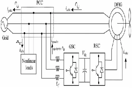
Fig. 1. Proposed system configuration
Working precept:on this paintings, a new manage algorithm for gscisproposed for compensating harmonics produced bynonlinear loads the use of an indirect modern-day control. Rscis used for controlling the reactive power of dfig.the other principal benefit of proposed dfig is that itworks as an active clear out even if the wind turbine isin shutdown condition. Therefore, it compensates loadreactive strength and harmonics at wind turbine stallingcase. Each simulation and experimental performancesof the proposed incorporated energetic filter out-primarily based dfigarepresented in this work. The dynamic overall performance ofthe proposed dfig is also tested for varyingwind speeds and adjustments in unbalanced nonlinearloads at factor of common place coupling.
In fig.1 shows a schematic diagram of theproposed DFIGbased WECS with integrated activefilter capabilities. DFIG, the stator is directlyconnected to the grid as shown in Figure. Two back-toback connected voltage source converters (VSCs) areplaced between the rotor and the grid. Nonlinear loadsare connected at PCC as shown in Fig. 1. Theproposed DFIG works as an active filter in addition tothe active power generation similar to normal DFIG.Harmonics generated by the nonlinear load connectedat the PCC distort the PCC voltage.
voltage-orientedreference frame. Synchronous reference frame (SRF)control method is used for extracting the fundamentalcomponent of load currents for the GSC control.
DESIGN OF DFIG-BASED WECS:
Selection of rankings of vscsand dc-hyperlink voltage isvery plenty crucial for the a hit operation ofwecs. Choice of DC-link Voltage:The dc-hyperlink voltage of VSC must be greater than twicethe peak of most phase voltage. Whileconsidering from the rotor aspect, the rotor voltage is sliptimes the stator voltage. So, the layout criteria for theselection of dc-link voltage may be done byconsidering handiest percent voltage. Even as thinking about fromthe GSC aspect, the percent line voltage (vab) is 230 V, asthe system is hooked up in delta mode.consequently, the dc-link voltage is anticipated as
𝑉𝑑𝑐≥
√2
2
√3 ∗ 𝑚𝑉𝑎𝑏
where
Vab is the line voltage at the PCC.
Maximum modulation index is selected as 1for linear range.
The value of dc-link voltage (Vdc) by (1) isestimated as 375 V.
Hence, it is selected as 375 V
Selection of VSC Rating: The DFIG draws a lagging volt-ampere reactive(VAR) for its excitation to build the rated air gapvoltage. , the rating of the VSC used as RSC Sratedisgiven as
𝑆𝑟𝑎𝑡𝑒𝑑 = √𝑃𝑟𝑚𝑎𝑥2 + 𝑄𝑟𝑚𝑎𝑥2
Design of Interfacing Inductor: The design of interfacing inductors between GSC andPCC depends upon allowable GSC current limit(igscpp), dc-link voltage, and switching frequency ofGSC. Maximum possible GSC line currents are usedfor the calculation. Maximum line current dependsupon the maximum power and the line voltage at GSC.The maximum possible power in the GSC is the slippower.Interfacing inductor between PCC and GSC isselected as 4 mH.
𝐿𝑖=
√3𝑚𝑣𝑑𝑐
12𝑎𝑓𝑚∆𝑖𝑔𝑠𝑐
= √3 × 1 × 375
12 × 1.5 × 10 000 × 0.25 × 3.76= 3.8𝑚𝐻
CONTROL STRATEGY:
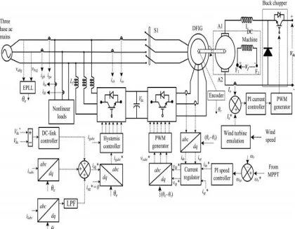
Control algorithms for both GSC and RSC arepresented in this section. The control algorithm for emulating wind turbine characteristics using dcmachine and Type A chopper is also shown in Fig. 2.
Fig. 2. Control algorithm of the proposed WECS.
Control of RSC:The main purpose of RSC is to extract maximumpower with independent control of active and reactivepowers. Here, the RSC is controlled in oltageoriented reference frame., the active andreactivepowers are controlled by controlling direct andquadrature axis rotor currents (idr and iqr).
Where:
The speed error (ωer) is obtained by subtractingsensed speed (ωr) from the reference speed (ω∗r ).
kpd and kid are the proportional and integralconstants of the speed controller.
ωer(k) and ωer(k − 1) are the speed errors at kth and (k−1)th instants.
Reference rotor speed (ω∗r ).
In general, the quadrature axis reference rotor current (i∗qr) is selected such that the stator reactive power (Qs) is made zero. In this DFIG, quadrature axisreference rotor current (i ∗qr) is selected for injecting
the required reactive power. Inner current controlloops are taken for control of actual direct andquadrature axis rotor currents (idr and iqr) close to thedirect and quadrature axis reference rotor currents (i∗dr and i ∗qr). The rotor currents idr and iqrarecalculated from the sensed rotor currents (ira, irb, and
irc).
Control of GSC:
The novelty of this work lies in the control of this GSCfor mitigating the harmonics produced by the nonlinearloads. The control block diagram of GSC is shown inFig. 2. Here, an indirect current control is applied onthe grid currents for making them sinusoidal andbalanced. Therefore, this GSC supplies the harmonicsfor making grid currents sinusoidal and balanced.These grid currents are calculated by subtracting theload currents from the summation of stator currentsand GSC currents. Active power component of GSCcurrent is obtained by processing the dc-link voltageerror (vdce) between reference and estimated dc-linkvoltage (V ∗ dc and Vdc) through PI controller as
Where kpdc and kidc are proportional and integral gains of dc-link voltage controller.Vdce(k) and Vdce(k− 1) are dclink voltage errors at kth and (k−1)thinstants. i∗gsc(k) and i ∗gsc(k − 1) are active powercomponent of GSC current at kth and (k−1)th instants.
III. SIMULATION RESULTS
The DFIG machine modes of operation namely sub-synchronous generating, super-synchronous
generating aresimulated and the waveforms for speed and stator, rotor power and torque in each of the above modes of operationare presented. The rotor speed is controlled by using v/f control and grid-side reactive power &Vdc are controlledby using voltage oriented control techniques. The grid-side current is controlled by using reference current controltechniques under p-q theory.
Fig 3 Matlab/simulinkdiagram of DFIG connected to
WECS
(b)
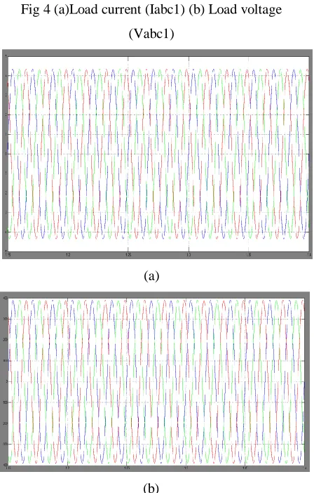
Fig 4 (a)Load current (Iabc1) (b) Load voltage
(Vabc1)
(a)
(b)
Fig 5 (a)grid current(Iabc) (b) grid voltage(Vabc)
(a)
(b)
Fig 6 FFT Analysis tool
IV. CONCLUSION
Proposed dfig, thereactive electricity for the induction machine has beensupplied from the rsc and the load reactive energy hasbeen furnished from the gsc. Decoupled manage ofboth active and reactive powers has carried out by rsccontrol. Dfig has also been proven at wind turbinestalling condition for compensating harmonics andreactive electricity of neighborhood hundreds. Proposed dfig-basedwecs with an integrated lively clear out has beensimulated the usage of matlab/simulink surroundings, andthe simulated results are verified with test results of thedeveloped prototype of this wecs.
REFERENCES
Management, ISSN (PRINT):2231–4407,Vol – 1,Issue – 3.
[2]. F. Poitiers, M. Machmoum, R. Le Doeuff and M.E. Zaim, “Control Of A Doubly-Fed Induction Generator For Wind Energy ConversionSystem”,GE44-LARGE
,Ecoleploytechnique de l`universite`de Nantes, Saint Nazaire, France.
[3]. R. Pena, J.C Clare and G.M Asher, “Doubly Fed Induction Generator Using Back -to-Back PWM Converter and Its Application ToVariable-Speed Wind Energy Generation”, IEEE Proceeding Electrical Power Application., Vol.143, NO.3, May1996, ISSN.,PP. 231-241.
[4]. T. Thiringer, A. Petersson, and T. Petru ,“Grid Disturbance Response Of Wind Turbine Equipped With Induction Generator and DoublyFed Induction Generator”, in Proceeding IEEE Power Engineering Society General Meeting, Vol.3, Toronto, Canada, July 2003,pp.1542-47.
[5]. A. Petersson, L. Harnefors, and T.Thiringer, “Evaluation Of Current Control Methods For Wind Turbines Using Doubly-Fed InductionMachine”, IEEE Transaction on Power Electrnoics.,Vol 20,No.1,Jan 2005,PP.227-235, July 2000.
[6] D. S. Zinger and E. Muljadi, “Annualized windenergy improvement using variable speeds,” IEEETrans. Ind. Appl., vol. 33, no. 6, pp. 1444– 1447,Nov./Dec. 1997.
[7] H. Polinder, F. F. A. van der Pijl, G. J. de Vilder,and P. J. Tavner, “Comparison of direct-drive andgeared generator concepts for wind turbines,” IEEETrans. Energy Convers., vol. 21, no. 3, pp. 725– 733,Sep. 2006.
[8] R. Datta and V. T. Ranganathan, “Variable-speedwind power generation using doubly fed wound rotorinduction machine—A comparison with alternativeschemes,” IEEE Trans. Energy Convers., vol. 17, no.3, pp. 414–421, Sep. 2002.
[9] E. Muljadi, C. P. Butterfield, B. Parsons, and AEllis, “Effect of variable speed wind turbine generatoron stability of a weak grid,” IEEE Trans. EnergyConvers., vol. 22, no. 1, pp. 29–36, Mar. 2007.
Authors: