Development of a Photovoltaic Module with
INC Maximum Power Point Tracking Control
System
Mohammad Asif
1, Ameenuddin Ahmed
2M. Tech Student [PS], Dept. of EEE, Al-Flah University, Faridabad, Haryana, India1 Assistant Professor, Dept. of EEE, Al-Flah University, Faridabad, Haryana, India2
ABSTRACT: At present, we are more concerned about the environmental issues caused by the consumption of conventional energy sources. That‟s why; we are focusing on the non-conventional energy sources like solar energy, wind energy, biomass energy, etc. to generate the required amount of electrical energy. Out of all the available energy resources solar energy is the most promising source of energy. But a photovoltaic system has two major drawbacks; the high installation cost and the low conversion efficiency of a PV system. To increase the efficiency of photovoltaic systems different types of MPPT techniques have been developed in past. In this paper we study and designed a PV system with incremental conductance (INC) based MPPT controller in SIMULINK. It also consists of a DC-DC converter. The implemented model extracts the maximum power from PV system and makes it available to the load hence it enhances the efficiency of the system.
KEYWORDS: INC, incremental conductance, MPPT, Simulink, DC-DC converter.
I.INTRODUCTION
The recent alteration in the environmental surroundings such as global warming and the speedy increase in the demand for electricity led to a need for new generation sources of energy that is cheaper and sustainable with reduced carbon emissions. Solar energy is the best solution of the problem to meet the energy demands in a clean and economic way. Solar energy is harnessed by using the solar cells which are the basic building blocks of solar power system. A solar cell converts the solar light directly into electricity by using photovoltaic effect. The Solar cells has nonlinear PV characteristics. These characteristics vary with the varying environmental conditions such as temperature and solar radiations [1]. Fig. 1 shows I-V and P-V characteristics of a PV system. As shown in fig. 1, there is an inimitable point at which PV system operates at maximum efficiency; this point is the maximum power point (MPP). To track this point a number of techniques have been proposed in literature, called Maximum power point tacking (MPPT) techniques. A MPPT is used to extract the maximum power from the PV system. Therefore it improves the efficiency of the PV system and hence reduces the cost.
Fig.1 I-V & P-V characteristics of PV system
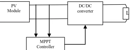
the source to transmit the maximum power [2]. In this work a dc-dc converter is connected in series with the PV module. Fig. 2 shows a series connection of dc-dc converter with a MPPT controller.
Fig.2 DC-DC converter in series with PV module
II
.
LITERATURE SURVEYA lot of work has been done in the past related to the PV modelling and different MPPT techniques to extract the maximum power from the PV system to make it more efficient. Sohan Lal et. al. in [1] discussed about three different MPPT techniques to increase the efficiency of the PV systems. Hairul Nissah Zainudin et. al. in [2] presents comparative study between two most popular algorithms technique which is incremental conductance algorithm and perturb and observe algorithm. The buck, boost and cuk converter was used in this study. A Matlab/Simulink based modeling and simulation of PV cell was presented in [3], [4] and [6]. They also discussed about the non-linear I-V characteristics of PV cell.Many methods to track Maximum Power Point (MPP) for PV arrays have been discussed by Trishan Esram et al [5]. The designing of DC-DC converter has been proposed in [8] and [9].
III
.
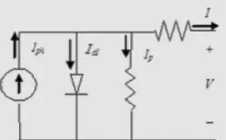
SOLAR CELL MODELINGA PV cell converts the solar energy directly into electricity, without polluting the environment. It has a PN junction made up of a semiconductor material. A variety of semiconductors is used to manufacture a PV cell using different types of manufacturing technology. A number of PV cells are connected in series or parallel to form PV array or modules. An equivalent circuit of an ideal solar cell is given below [4].
Fig. 3 Equivalent circuit of Ideal single diode model
The output current „I‟ is given as:
I = IPh – Id (1)
Here Id is the current of diode connected in anti-parallel with light generated current source and Iph is the photocurrent.
Diode current is given as:
1
akT qV exp o I d
I (2)
V is the voltage imposed on diode; „Io‟ is the reverse saturation current, „k‟ is the Boltzmann constant (1.38065*10 -23
J/K), „q‟ is the electron charge (1.602176*10-19 C), „T‟ is the junction temperature; „a‟ is the diode ideality constant. In practical case it is necessary to take into account series resistance RS and parallel resistance RP as they affected the
efficiency of the PV cell. Fig. 4 shows a practical PV cell‟s equivalent circuit.
PV Module
DC/DC converter
MPPT Controller
Fig. 4 Equivalent circuit of a practical model with Rs and Rp
Now current is given as:
I = IPh - Id - IP (3)
Where IP = current leak in parallel resistor.
Now the current equation can be given as:
P s t
s o
ph
R I R V 1 a V
IR V exp I I
I
(4)
Above equation describe the single diode model we considered. Table 1 shows the parameters we have taken for modelling of a PV system at a temperature of 30°C and solar insolation of 500w/m2.
Table.1 Electrical Parameters for PV system modelling
S. No. Symbols Values
1. Tref 25°C
2. Sref 1000w/m2
3. Voc 66
4. Vm 54.2
5. Isc 25.44
6. Im 23.25
Fig. 5 shown below is the simulink subsystem of a PV module for 30°C temperature and 500 w/m2 is the solar irradiance.
Fig.5 Simulink subsystem of PV Module
Fig.6 Internal circuit of the simulink PV subsystem
IV.DC-DC CONVERTER
A DC-DC converter is a power optimizer that is widely used in PV systems as an interface between PV module and the load. It is used to deliver the maximum power from the source i.e. solar module to the load.Basically three types of dc-dc converter circuits, termed as buck, boost and buck-boost are used for this purpose. In this paper we have used a boost converter with IGBT as a switch. It is a power converter with an output voltage greater than its input voltage and output current is smaller than the input current. Fig.7 shows the basic circuit diagram of Boost converter.
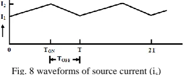
Fig.7 Circuit diagram of a Boost converter The figure given below shows the waveform of source current (is).
Fig. 8 waveforms of source current (is)
When switch „S‟ is „ON‟, the output voltage Vo is zero and current from source (is) starts flowing across the inductance
„L‟. The equation of this circuit can be given as:
dt s di L s
V or
L s V dt
s di
during interval Tonto (5)
When switch „S‟ is „OFF‟, current (is) starts decreasing and the equation during OFF period (Toff = T-Ton) for this
circuit can be given as:
dt s di L o V s
V or
L o V s V dt
s
di during interval
on
T t
T (6)
Therefore we can write expression for on T min I max I on T 1 I 2 I dt s di
(7)
By comparing the above equation with equation 2, we get
on s s T L / V dt di
(8)
Similarly in time interval Toff , current goes from I2 (Imax) to I1 (Imin) and therefore we get the expression for
off T L / s V o V off T min I max I off T 1 I 2 I dt sdi (9)
From equations (8) & (9),
off s o on s
T
L
/
V
V
T
L
/
V
(10)From above equation we get the average output voltage given as:
k 1 1 V T / T 1 1 V V s on so (11)
Here time period, T = Toff + Ton and duty ratio,
off on on on T T T T T k
with range of
1
k
0
Fig. 9 Boost converter simulink model
A boost converter model developed in simulink is shown above in above figure.
V.MAXIMUM POWER POINT TRACKING CONTROL METHODS
In a PV system, tracking the maximum power point is an important part to improve the efficiency of the PV system. Many MPPT algorithms have been developed and presented in past. All these algorithms or techniques to track MPP vary in some respects such as; complexity, sensors requirement, speed of convergence, overall cost, range of efficacy, and attractiveness. Some of them are Perturb and Observe (P&O), Incremental conductance (INC) method, Parasitic Capacitance (PC), Fractional open circuit voltage, Fractional short circuit current, neural network, fuzzy logic control etc [5]. Out of them in this paper we discussed about INC method.
VI
.
INCREMENTAL CONDUCTANCE METHODDue to some drawbacks of P&O algorithm, we used incremental conductance (INC) method. The incremental conductance (INC) technique is based on the information that the PV array power curve slope is either zero at the Maximum Power Point, positive on the left, or negative on the right, as specified by equations:
At Maximum power point,dP dV0, at Left of maximum power point, dPdV> 0, and at Right of maximum power
point, dP dV< 0.
As P = IV, therefore
V I V I dV dI V I dV IV d dV dP
Therefore from above equations we can write,
At maximum power point,
I
V
I
V
, at Left of maximum power point, IV> I V, and at Right of maximum power point
I
V
< I VFig.10 Flow chart of INC MPPT algorithm
Fig.11 represents the simulink model of INC MPPT algorithm.
Fig.11 Simulink model of INC MPPT algorithm
The figure given below shows the whole simulink model of PV system with INC MPPT controller that we have implemented in simulink.
VII.RESULTS AND DISCUSSION
From the simulink model of photovoltaic (PV) module with incremental conductance (INC) based maximum power point tracking (MPPT) control system we observe different values of output current, voltages and power from the module. Different waveforms shown below are the results we obtained from simulink model.
Fig.13 output current of Boost converter
Above figure shows the output current of boost converter.
Fig.14 output voltage of Boost converter
Above figure shows the voltages of boost converter.
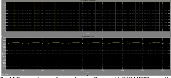
Fig. 15 Duty cycle waveform and output Power with INC MPPT controller
Fig.16 Complete output waveform of power with and without MPPT controller
The figure shown below is the combined waveform of output power with and without MPPT controller.
VIII.CONCLUSION
In this paper a PV system with MPPT controller using incremental conductance algorithm has been simulated. It helps the system to track the maximum power point MPP without much affecting by varying weather conditions like. It draws the maximum power from the system. Hence it improves the efficiency of the system and reduces the overall cost of the system.
REFERENCES
[1] Sohan Lal, Rohtash Dhiman, Mr.S.K.Sinha, “Analysis Different MPPT techniques for Phoovoltaic systems,” IJEIT Volume 2, Issue 6, December 2012.
[2] Hairul Nissah Zainudin, Saad Mekhilef, “Comparison Study of Maximum Power Point Tracker Techniques for PV Systems,” Proceedings of the 14th International Middle East Power Systems Conference (MEPCON‟10), Cairo University, Egypt, pp. 750-755, 19-21December 2010. [3] Tarak Salmi, Mounir Bouzguenda, Adel Gastli, Ahmed Masmoudi, “ MATLAB/Simulink Based Modelling of Solar Photovoltaic Cell,”
IJRER Vol.2, No.2, 2012
[4] Habbati Bellia, Ramdani Youcef, Moulay Fatima, “A detailed modeling of photovoltaic module using MATLAB,” NRIAG Journal of Astronomy and Geophysics, pp.53–61, 3 (2014).
[5] T. Esram and P. L. Chapman, “Comparison of photovoltaic array maximum power point tracking techniques,” IEEE Trans. on Energy Conversion, vol. 22, no. 2, June 2007.
[6] M. G. Villalva, J. R. Gazoli, and E. R. Filho, “Comprehensive approach to modeling and simulation of photovoltaic arrays,” IEEE Trans. on power Electron. vol. 24, no. 5, May 2009
[7] Eftichios Koutroulis, Kostas Kalaitzakis, and Nicholas C. Voulgaris, “Development of a Microcontroller-Based Photovoltaic Maximum Power Point Tracking Control System,” IEEE TRANSACTIONS ON POWER ELECTRONICS, VOL. 16, NO. 1, JANUARY 2001.
[8] S.Kolsi, H.Samet, M. Ben Amar, “Design analysis of DC – DC Converters connected to a PV generator and controlled by MPPT for optimal energy transfer throughout a clear day,” Journal of Power and energy Engineering, pp.27-34, 2(2014).
[9] Dhananjay chaudhary, Anmol Ratna SAxena, “DC-DC Buck Converter For MPPT of PV Systems,” IJETAE ISSN 2250-2459, Volume 4, Issue 7, July 2014.
BIOGRAPHY
Mohammad Asif was born on 30th June 1990 in Firozabad, UP, India. He received the graduation degree in Electrical and Electronics Engineering in 2013 from MDU, Haryana. Currently he is pursuing Master‟s in Power Systems from MDU Haryana. His research interests include power generation using renewable energy resources and power controlling using FACTs devices.