A Study and Design of Circulating Current
and DC Current Ripple Controlling MMC
S.Vijay Kumar
M.Tech(Digital Systems And Computer Electronics), JNTUH
R.Srikanth
M.E.(Bio Medical Engineering), UCEOU
Vuppari Prabhakar
M.Tech(Energy Systems), JNTUCEAABSTRACT:MMC is an evolving topology which is
able to handle high voltage and power
ratings.Under the unbalanced condition, the main theme of controlis to decrease the negative-sequence line current. Moreover,the circulating current of a MMC contains not only double-linenegative-sequence component, which appears under the balancedcondition, but also positive- and zero-sequence double-line components. Thus the controller should be able to remove all those components of the circulating current. A proportional-resonantcontroller (PR controller) is applied to regulate the positive- andnegative-sequence components of circulating current. In
addition,the zero-sequence component of
circulating current is controlledby a dc current
controller. The proposed control method
isconfirmed in MATLAB/SimPowerSystem.
KEYWORDS-Modular multilevel converter (MMC), Circulating Current Suppression Control, DC Current Ripple Control,Proportion Resonance Controller
I. INTRODUCTION
AC has been the desired international platform for electrical transmission to homesand corporations for the beyond 100 years. And but high-voltage AC transmission hassome limitations, beginning with transmission potential and distance constraints, andthe impossibility of immediately connecting two AC electricity networks of various frequencies. With the dawn of a brand new energy era and the want to construct a smarter grid,HVDC is predicted to develop some distance past its
traditional function as a complement to ACtransmission [2].
Figure 1.1: HVDC transmission system from an offshore to onshore grid [1]
Modular Multilevel Converters (MMCs) have won researcher’s attention due totheir potential to deal with excessive voltage and energy ratings. VSC-HVDC is getting increasingly more important for integrating renewable power assets together with large offshorewind farms, offering bendy interconnection among vulnerable AC grid networkthe use of back-to-returned configuration, or truly transmitting electricity using undergroundcables. The VSC-HVDC additionally has speedy and particular manage over the lively strength-flowin addition to it could independently control the reactive power injection on the nearby acgrid. There are numerous operational MMC-HVDC tasks which include HVDC PLUS(Siemens) with an 88km undersea transmission hyperlink between San Francisco’s CityCentre electric power grid and a substation near Pittsburg. The important assisting functions HVDC PLUS affords are AC voltage Control, black-begin functionality,compact converter station space utilization, four quadrant operation, repayment ofasymmetrical masses, bendy integration into HVDC multi terminal structures or future HVDC grids. Its primary running principle and different blessings each on thetechnical in addition to on the budget friendly thing may be described in [3] [4].
Another MMC-HVDC set up named HVDC Light by using ABB, is an versionof HVDC classic used to transmit strength in strength tiers (50-2500MW) transmitted using overhead lines and enviornmental pleasant underground and sub-sea cables.It is used for grid interconnections and offshore links to wind farms. With HVDCLight, it's far feasible to transmit energy in both instructions and to guide existing ACgrids a good way to increase robustness, stability, reliability and
controllability. HVDCLight gives many other advantages and may be utilized in extraordinary programs whichis explained in [5]. As mentioned before, the principle trouble of the 2 degree converter is its excessive switching losses due to exceedingly high switching frequency which necessitates excessive insulation necessities of the transformer, as well as filters. The use ofmodular multilevel converters overcomes most of the aforementioned shortcomings,but on the expense of two times as many semi-engaging in devices and a big allottedcapacitor for each submodule. The precept idea of the hybrid VSC-HVDC, as usedin HVDC MaxSine evolved by Alstom, is to use a stage converter as the principleswitching aspect with low switching frequency and an MMC to provide a voltagewave shaping function on the AC side so that you can do away with the harmonics [6] [7].
II. PROPOSEDCONTROL STRATEGY
Multilevel converters are classified into diode-clampedmultilevel converters (DCMCs), flying-capacitor multilevelconverters (FCMCs), cascaded H-bridge converters (CHBCs),and modular multilevel converters (MMCs). MMCs havebeen widely adopted in VSC-HVDC systems. Fig. 1 showsthe structure of an MMC consisting of six arms. Each armis composed of an inductor and a series of connected halfbridge sub-modules (SMs). HVDC-MMC systems requireseveral design techniques. (1) System parameter designincludes inductance and capacitance design and switchingdevice current capacity design. (2) System control designincludes power (DC-link voltage) control, AC-sidecurrent control, circulating current control, and SM voltagebalancing [2-6].
Fig. 1. Basic structure of MMC.
The SM capacitorvoltage ripple has line-frequency and double-line-frequencycomponents. However, this design method did not separateline-frequency and double-line-frequency components; thecapacitor voltage ripple was only calculated using integratedcomponents.
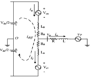
The output ofsub-module is either Uc or 0 depending on the gate statement.When N is big enough or the switching frequency is highenough, the voltage injection to each arm by sub-modules canbe considered as continuous. For DC side voltage, with bigDC-side capacitor, the dc-side voltage can be considered as aconstant value. Thus, the single phase-equivalent circuit of aMMC can be expressed as Fig. 2.
Fig. 2. Single phase equivalent circuit of MMC
In Fig. 2, The upper and lower arm current are named as iuand il; the converter’s output current and voltage are
named asio and vo respectively. The circulating current flowing withinthe converter is denoted as idiff. Since the upper and lowerarm are symmetric, ideally both lower and upper arm currentscontain half of the converter output current.
III. CONTROL SYSTEM UNDER UNBALANCED VOLTAGE
A. PR Controller
PR control can achieve high bandwidth at certain resonantfrequency. Through PR control, measurement signal can trackthe reference signal without steady-state error at the resonancefrequency.
B. Outer Loop Power Control
When the grid side voltage is under unbalanced condition,the line current and power flow are separated in positive-, negative- and zero-sequence components. With a zero-sequence current controller, thezero-sequence current can be reduced to zero. Therefore theobjective of the unbalance controller is the negative componentof line current.
C. Inner Loop Current Control
Different control objectives have been set for MMC underunbalanced condition. Reference [15] tried to reduce thenegative components of the line current to zero.
D. Grid-side Zero-Sequence Current Control
The overall control structure is shown in Fig.4. The zerosequence current occurs during the unbalanced condition. AY−to−∆ transformer can stop the zero sequence current.However, when the fault happens on the transformer or between the transformer and MMC, zero-sequence current willnot be stopped by transformer.
E. Circulating Current Control and Dc Current Ripple Control
power foreach phase has a negative-sequence double line frequencycomponent.
When the ac-side voltage has negative component, theinstantaneous power of each phase consist not only negativesequence but also positive- and zero-sequence double-linefrequency components. Therefore, to eliminate the circulatingcurrent under unbalanced condition, the controller in positive-,negative- and, zero-sequence are all needed.
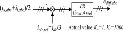
It’sdc component is set as the reference of the PR controller. Theoutput of PR controller is the positive- and negative-sequencecomponents of the reference inner unbalanced voltage, whichis noted as ediff;abc in Fig. 3.
Fig. 3. Circulating current suppression controller. For a three-phase system, the sum of positive- and negativesequence current are zero. However the sum of zero-sequencecomponent is not zero. And idc is the sum of three-phase current. Therefore, if the three-phase current has zero-sequencecomponent, then idc includes the zero-sequence componentripple. Normally, a Y-to-δ transformer can stop the zerosequence line current. However, when the fault happensbetween the transformer and MMC, or the system has notransformer, it is necessary to eliminate the zero-sequence linecurrent. The controller to eliminate zero-sequence current isshown in Fig. 4. As shown in Fig. 3, the output of the zerosequence line current controller is added to the output of theinner loop current controller as a zero-sequence component.
Fig. 4. Zero-sequence line current controller.
If we assume there is no power loss on MMC. Then theac-side power of MMC should be equal to the dc-side powerof MMC. So the dc component of the dc-side current can beeasily set as Idc;ref = Pout=Vdc. Where Pout is the ac-sideoutput power of MMC and Vdc is the dc supply voltage ofMMC. A PR controller is used to control the zero-sequenceof the inner difference current to Idc;ref. The output of PRcontroller is the zero-sequence component of the referenceinner difference voltage. Beside the double-line frequencyripple, the dc current ripple controller can also cancel theresonance current caused by LC circuit resonant. A controlleris added to reduce the dc current ripple as shown in Fig. 5. Theoutput of the dc current ripple controller is added to the outputof the circulating current suppression controller as shown inFig. 3.
Fig.5. DC-side current ripple controller. IV. SIMULATION RESULTS
A simulation of the proposed system is conducted inMATLAB SimPowerSystem. The simulation environment andparameters are listed in table I. At t =0:2s the circulatingcurrent controller and the controller to eliminate the dc currentripple is activated. From t = 0:6s to t = 0:8s, there is a0:2pu negative-sequence component voltage on the grid side.Regardless of the start-up process, the capacitor voltages ofsub modules were charged at nominal value at beginning.
B. Performance of the control system
Fig.6 shows the output real power of the MMC. During the unbalanced voltage condition (t from 0:6 to 0:8), the output power has a double-line frequency component. When I− is zero, with a non zero V −
Fig. 6. Output real power of converter.
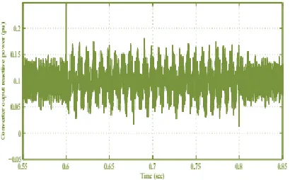
Fig.7 shows the output reactive power of the MMC. As thesame with the output active power. During the unbalanced gridcondition, there is a double-line frequency component appearon the converter output reactive power.
Fig. 7. Output reactive power of converter
Fig.8 is the grid current of MMC during the unbalancecondition. The ripple during the unbalanced condition is dueto the changing of the power and reactive power. The outloop power controller tries to regulate the converter powerto reference value. So the ripple of the power leads a ripplein current reference in dq frame, and the ripple for referencecurrent in dq frame causes a ripple of line current in abc frame.
Fig. 8. Grid current of MMC
Fig. 9 is the zero-sequence component of line current. After applying the zero-sequence current controller at t = 0:1s,the magnitude of the zero-sequence current is reduced duringboth balanced and unbalanced condition.
Fig. 9. Zero-sequence component of line current of MMC
V. CONCLUSION
Investigative study of the internal unbalances in an MMC has been approved out.This unbalance can be a result of the asymmetries, non linearities and change in the tolerances of the components as for illustration arm inductors andsubmodule capacitors used in an MMC. When the negative-sequence componentof the line current during unbalanced condition is controlled tozero, there is a double-line frequency component on the outputpower of MMC during unbalanced condition. With proper nonzero negative-sequence line current, the double-line frequencycomponent of the output real power can be eliminated. ThePR controller reduces both positive- and negative-sequencecomponents of the circulating current during the unbalancedcondition. In addition, a dc current controller is appliedto reduce the zero-sequence of the circulating current andresonance current on the dc-side of MMC.
REFERENCES
[2] ABB, “HVDC over HVAC,” http://new.abb.com/systems/hvdc/why-hvdc.
[3] Siemens, “HVDC PLUS VSC Technology,”
http://www.energy.siemens.com/mx/en/power-transmission/hvdc/hvdc-lus.htm#content=%20Topology. [4] “Basics and principle operation of HVDCPLUS,” http://www.energy.siemens.com/br/pool/hq/power-transmission/HVDC/HVDC_Plus_Basic%20and%20Prin cipals.pdf.
[5] ABB, “HVDC Light, It’s time to connect,” http://new.abb.com/docs/default-source/ewea-doc/hvdc-light.pdf?sfvrsn=2.
[6] Alstom, “HVDC-VSC transmission technology of the future,”
https://www.gegridsolutions.com/alstomenergy/grid/Glob al/Grid/Resources/Documents/Smart%20Grid/Think-Grid-08-%20EN.pdf.
[7] M. Winkelnkemper, A. Korn, and P. Steimer, “A modular direct converterfor transformerless rail interties,” in Industrial Electronics (ISIE), 2010IEEE International Symposium on, July 2010, pp. 562–567. [8] Q. Tu, Z. Xu, and L. Xu, “Reduced switching-frequency modulationand circulating current suppression for modular multilevel converters,”Power Delivery, IEEE Transactions on, vol. 26, no. 3, pp. 2009–2017,July 2011. [9] L. Harnefors, A. Antonopoulos, S. Norrga, L. Angquist, and H.-P.Nee, “Dynamic analysis of modular multilevel converters,” IndustrialElectronics, IEEE Transactions on, vol. 60, no. 7, pp. 2526–2537, July2013. [10] Y. Ma, L. Fan, and Z. Miao, “Integrated control and switching strategyfor a grid-connected modular multilevel converter,” in PES GeneralMeeting, 2015 IEEE, accepted, July 2015, pp. 1–5.
[11] X. She, A. Huang, X. Ni, and R. Burgos, “Ac circulating currentssuppression in modular multilevel converter,” in IECON 2012 - 38th
Annual Conference on IEEE Industrial Electronics Society, Oct 2012,pp. 191– 196.
[12] Y. Ma, Z. Miao, V. R. Disfani, and L. Fan, “A one-step model predictivecontrol for modular multilevel
converters,” in PES General Meeting Conference Exposition, 2014 IEEE, July 2014, pp. 1–5
[13] L. Fan, R. Kavasseri, H. Yin, C. Zhu, and M. Hu, “Control of DFIGfor rotor current harmonics elimination,” in Power & Energy SocietyGeneral Meeting, 2009. PES’09. IEEE. IEEE, 2009, pp. 1–7. [14] L. Fan, H. Yin, and Z. Miao, “A novel control scheme for DFIG-basedwind energy systems under unbalanced grid conditions,” Electric PowerSystems Research, vol. 81, no. 2, pp. 254–262, 2011.
[15] M. Guan and Z. Xu, “Modeling and control of a modular multilevelconverter-based hvdc system under unbalanced grid conditions,” PowerElectronics, IEEE Transactions on, vol. 27, no. 12, pp. 4858–4867, Dec2012.
Authors Details:
S.Vijay Kumar completed M.Tech(Digital Systems And Computer Electronics) from JNTUH
R.Srikanth completed M.E.(Bio Medical Engineering) from UCEOU.
![Figure 1.1: HVDC transmission system from an offshore to onshore grid [1]](https://thumb-us.123doks.com/thumbv2/123dok_us/7773492.1280924/2.612.62.280.39.202/figure-hvdc-transmission-system-from-offshore-onshore-grid.webp)