ISSN 2348 – 7968
258
Shakedown and limit load of pipe bends with local wall thinning
under combined internal pressure and cyclic in-plane bending
moment
W.E. Abdel-Ghany1, S.J Ebeid2 and M.R Kasem3
1, 2 Department of Design and Production Engineering
Faculty of Engineering, Ain Shams University, Cairo, Egypt
3 Mechanical Engineer, CAIROMATIC, Cairo, Egypt
Abstract
The behaviour of smooth 90-degree pipe bends under combined internal pressure and cyclic bending loads has received a substantial attention in recent few years where shakedown and ratcheting boundaries have been determined. However such data are scarcely found for those pipe bends suffering from local wall thinning. This paper quantifies the effect of local wall thinning parameters on both elastic and shakedown boundaries via a non cyclic-numerical technique developed by Abdalla et al. [1]. The effect of local wall thinning parameters is investigated also on limit loads of pipe bends under the internal pressure and bending moments based on a systematic FE limit loads using elastic perfect plastic material model. The limit load study has been verified with the proposed approximations developed by Oh et al. [2] and Kim et al. [3]. The thinning geometry is assumed to be rectangular rather than circular but the geometrical nonlinearities are considered. Finite and fully circumferential local wall thinning in pipe bends under combined internal pressure and in-plane bending; opening and closing have been studied. Both extrados and intrados local wall thinning locations have been considered also.
Keywords: Finite Element, Pipe Bends, Shakedown,
Reversed Plasticity, Ratcheting, Local Wall Thinning, Twice-Elastic-Slope, Plastic Load
1.
Introduction
Pipe bends are considered the most critical components in piping systems, especially in nuclear power plants and natural gas pipe lines. They are incorporated into piping systems to allow modifications in isometric routings and maintain integrity of piping systems under transient loading conditions by absorbing the thermal expansions and seismic movements by dissipating energy as a result of
local plastic deformation. On the other hand due to their specific deformation behaviour when being used beyond their elastic limit, they are capable of plasticizing over large areas when the system is overstressed. However, care must be taken so that deformations of the bend remain predominantly elastic. Otherwise, the resistance to deformation may decrease rapidly leading to the failure of the system. It is, therefore, important to know its collapse load for the safe operation of the plant. Not only do not the pipe bends suffer from conventional applied loads, but they also suffer from several environmental effects such as erosion and corrosion. Erosion and corrosion effects can be found from the inside running fluid or outside corrosion from the inside running fluid or outside corrosion from moisture or acidic media. All these types of attacks lead to general and localized metal loss.
ISSN 2348 – 7968
259 In order to assess FFS of the local wall thinning in pipe
bends, determination of plastic limit is importantly needed to estimate the maximum load carrying capacities of these pipe bends under load combination.
API 579-1[2] code defines the limit load; as a failure criteria is applied only for steady loads which are generally
uncommon in pressurized components. Most of pressurized components operate under low cycle fatigue conditions which require the determination of the shakedown limit load for safe operation. Full elastic-plastic cyclic loading FE analyses are implemented by API 579-1[2] standard. Such lengthy time consuming analyses
Nomenclature rm Mean cross sectional radius of pipe
d Local wall thinning depth t Thickness of pipe bend
i
d Inner diameter of pipe Greek symbols
o
d Outer diameter of pipe εo Material initial yield strain
E Young’s modulus α Thermal expansion coefficient
o
F Normalized limit load for circumferential
part-through constant depth surface crack λ
Pipe bend characteristics, 2 m = Rt r
ΔT Temperature difference
F¥ Normalized limit load for sufficiently long wall thinning
σ Stress
E
σ Elastic stress component
L Length of straight pipe σELPL Elastic-plastic stress component
Half axial (longitudinal) length of local wall thinning σeq Equivalent plastic stress
o
σ Limit stress of an elastic perfect plastic material
M In-plane bending moment
Mi Incremental in-plane bending moment σr Residual stress component
L
M Limit in-plane bending moment of defective
pipe bend
z x y r
r r
σ σ σ, , Residual normal stress components
u
σ Ultimate tensile strength
o
M Limit in-plane bending moment of smooth pipe
bend (without any defect)
y
σ Yield strength
τrx,τry,τrz Residual shear stress components A
o
M Plastic collapse moment solution for pipe bend
from ASME BPVC θ
Half axial circumferential angle of local wall thinning
C o
M Plastic collapse moment solution for pipe bend
by Chattopadhyay and co-workers ϕ
Half axial longitudinal angle of local wall thinning
D o
M Plastic collapse moment solution for pipe bend from ductile fracture handbook Abbreviations
API American petroleum institute
Exp o
M Experimental plastic collapse moment ASME American society for mechanical engineers
ECM Elastic compensation method
K o
M Plastic collapse moment solution for pipe bend
by Kim and co-workers
LMM
Linear matching methodFAC Flow accelerated corrosion
s o M
Limit in-plane bending moment of smooth straight pipe = 4σor tm2
FE
Finite elementFFS Fitness for service
SD
M Shakedown limit moment IPC In-plane closing
P Internal pressure IPO In-plane opening
L
P Limit pressure of defective pipe bend PCM Plastic collapse moment
O
P Limit pressure of smooth pipe bend SD Shakedown
S O
P Limit pressure of straight pipe,= 2 3σοt rm TED Twice elastic deflection
PEQ Equivalent plastic strain TES Twice elastic slope
ISSN 2348 – 7968
260 cannot determine the RSF (RSF = limit or plastic collapse
load of damaged component / limit or plastic collapse load of undamaged component) for the component directly. It just performs the analysis based on the design load and checks if a given load is safe or not according to the failure criteria.
Extensive experimental and analytical works have been proposed for straight pipes with local wall thinning by Oh et al. [3] and Kim et al. [4]. For elbows and pipe bends; Oh et al. [5] and [6] proposed assessment equations for internal pressure and bending moment loads, but these studies are limited for combined loads and cyclic ones. So this paper quantifies the effect of local thinning parameters on the pipe bends under combined loads besides to a comparative verification with the Kim et al. [6] and Oh et al. [5] proposed equations. The wall thinning shape can be rectangular or circular but this study is limited on rectangular local wall thinning. Kim et al. [6] studied the effect of the circular wall thinning on pipe bends under combined internal pressure and IPC bending moment. Oyamada et al. [7] studied the effect of the external local wall thinning on pipe bends under combined internal pressure and bending moments.
The current study is limited to the rectangular internal local wall thinning. This is done through a systematic 3D FE limit analysis using elastic-perfectly plastic material model with invoked geometrical non-linearity. Also shakedown and elastic boundaries of those pipe bends are proposed in this paper via a non cyclic-numerical technique developed by Abdalla et al. [1]. Finite and fully circumferential rectangular local wall thinning geometries are studied for symmetric axial wall thinning and extended ones. Both IPC and IPO moments are incorporated in this study for both extrados and intrados locations.
2.
Finite element analysis
Finite element analysis is used to conduct the investigation of SD and collapse loads of pipe bends of various sizes under the effect of the combined internal pressure and bending moments via a general purpose finite element program ABAQUS [8]
2.1.Geometry
Fig. 1 depicts a 90° pipe bend characterized by two dimensional variables R/r and r/t leading to another non-dimensional pipe bend characteristic λdefined by
m 2
m m
(R r ) Rt
λ= = (r t)
r (1) Where R is the mean bend radius of the elbow, rm and t
are the mean cross sectional radius and the wall thickness of the elbow.
To study the behaviour of pipe bend geometry, four different sets of
m
r t and R / r were considered in this study as depicted in Table 1. The pipe bend system considered consists of 90° elbow and the attached straight pipe of length L
, where L is chosen to be twenty times the elbow’s cross sectional radius, L = 20rm, to avoid the end effects and to accommodate the free ovalization effect of the elbow cross section on plastic loads due to the effect of geometrical nonlinearities. Due to symmetry, only 45° portion of the pipe bend along the longitudinal direction and 180° in the circumferential one was considered to utilize the mesh refinement and reduce the consumed running time.
2.1.1.The shape of wall thinning
The shape of the wall thinning is assumed to be rectangular of constant depth in both longitudinal and circumferential directions. The location of the wall thinning was considered to be internal at both extrados and intrados o the elbow. The rectangular wall thinning depicted in Fig. 2, 3 and 4 is characterized by the following parameters, the wall thinning depth d, the half circumferential angle θ, the longitudinal angleφand half longitudinal length of local wall thinning. The above mentioned parameters lead to four non-dimensional variablesd t,θ π 4φ πand do.
Table 1 Geometry of pipe bends
m
r t r tm R rm λ= Rt rm2
50 5 10 2 0.2
50 2.5 20 6 0.3
50 10 5 2 0.4
50 5 10 5 0.5
ISSN 2348 – 7968
261 Fig. 2 Schematic illustration of 90°pipe bend with finite extrados local wall thinning under in-plane bending; (a) the cross section of wall thinning, (b) characteristics of elbow wall thinning and (c) characteristics of longitudinal extent of wall thinning.
Fig. 3 Schematic illustration of 90°pipe bend with finite intrados local wall thinning under in-plane bending; (a) the cross section of wall thinning, (b) characteristics of elbow wall thinning and (c) characteristics of longitudinal extent of wall thinning.
ISSN 2348 – 7968
262 In this study four values for d twere consideredd t=0.1,
0.3, 0.5 and 0.7 and four values forθ π, θ π=0.1, 0.3, 0.5 and 1 to cover the finite and the fully circumferential wall thinning as depicted in Fig. 2, 3 and 4.Wide range of longitudinal extent of local wall thinning ranges from 0.25 to 3 to study the extent of wall thinning from the elbow to the attached straight pipe. The extended longitudinal wall thinning angle
is defined by1 2
4 x R
(2)
Where
x
denotes the longitudinal length of local wall thinning in the attached straight as shown in Fig. 2c, 3c and 4c. The limiting case of 4 indicates that the thinning exists in the entire elbow.The other limiting case is the thinning without longitudinal extent. Also do ranges from 0 to 2. The length of the longitudinal extent depends on the thinning location and whether the thinning is finite or fully circumferential. Hence the previous values of the aforementioned parameters cover the locations of local wall thinning at both extrados and intrados.
Pipe bends contains local wall thinning with zero longitudinal length corresponds to circumferential part-through constant depth surface cracks which is characterized by two non-dimensional parameters a/t and
, where denotes the half crack length Fig. 2, 3 and
4. The value of is systematically varied
from =0and =0.5 while the relative crack depth a/t is varied from a/t=0.2 to a/t=0.8.
2.2. Material
Material non-linearity was considered in this study. This was implemented by using ‘elastic perfectly plastic’ material model. The effect of the strain hardening of the material was eliminated by using this model. Materials used with young’s modulus E , yield strengthσy and
Poisson’s ratioυrespectively as 200 Gpa, 200 Mpa and 0.3. Using the abovementioned constant values do not affect the results of the present case study, as normalized values are considered. Prabhakaran et al. [9] Performed an exercise to study this effect and it is observed that plastic collapse moment is more depended onσy than elastic modulus E . In general it can be concluded that for metallic materials that are generally used in piping industry, the effect of yield strengthσy to elastic modulus E is minimal.
2.3. Element and meshing
The C3D20R, 20-node quadratic brick, reduced integration element was preferred to avoid problems associated from incompressibility.
Due to symmetry, only one fourth of the pipe bend was modeled. Mesh refinements were achieved thus for smooth pipe bend; the number of element ranges from 1,000 to 1,500 elements with 8,000 to 12,000 nodes. The model was meshed with twenty elements across the circumference, fifteen elements across the axis of the elbow, five elements across the axis of the attached straight pipe and three elements through the thickness as depicted in Fig. 5. For Pipe bend with local wall thinning; the number of element ranges from 1,000 to 1,500 elements with 8,000 to 12,000 nodes where four elements were used through the thickness and twenty elements across the circumference of the elbow cross section while the longitudinal direction of the elbow was meshed with sixteen elements as depicted in Fig. 6.
Pipe bends contains thinning with zero longitudinal length corresponds to part-through constant depth surface cracks which were characterized by two parameters; a tand
θ πas depicted in Fig. 7, whereθ πis the circumferential crack angle that was varied from 0.1, 0.3, and 0.5 while
a tis the ratio of crack depth (
a
) and pipe bend thickness (t
) that was varied from 0.2 to 0.8. The circumferentialFig. 5 Finite element quarter model of the smooth pipe bend
ISSN 2348 – 7968
263 constant depth part- through surface crack model was
meshed with eight divisions in the circumferential direction and three divisions in the radial direction at the spider web. At the crack face 16 divisions across the crack length and six divisions across the crack depth have been employed.
2.4. Loading and boundary conditions
The load on the pipe has two components: a “dead” load, consisting of internal pressure (with a closed end condition), and a “live” in-plane bending moment applied to the end of the system. Combined internal pressure and in-plane bending moment are applied in a non-proportional manner, that is internal pressure is applied to the model in an initial step and then held constant in the second analysis step while the bending moment is increased monotonically. The rationale behind keeping pressure constant is that internal pressure generally does not increase during service whereas; bending moment may
increase significantly in an accidental condition. Thus it is of interest to predict PCM of an elbow for a constant internal pressure. Internal pressure is applied as a distributed load to the inner surface of the FE model. In addition, an equivalent pressureP1 is applied at the end of
the pipe to simulate closed end defined by
i o i
2 2 2 1
P =P. d d -d
(3) For bending loading, rotation is applied at the nodes at the end of the pipe, constrained using the kinematic coupling option within ABAQUS [8]. Sufficiently large deformation (rotation) was directly applied to the constrained (master) node. The bending moment is directly determined from the nodal force of the master node. Symmetry in the pipe bend geometry was utilized and therefore, one fourth of the model which is symmetric about both; longitudinal and circumferential planes, as shown in Fig. 8. The quarter model has symmetry boundary condition on the longitudinal edges (Z-Symmetry) and (Y-(Z-Symmetry) on the middle of the elbow. The model is hinged at the top most extrados point. The point of load application was assigned a Z-rotation boundary condition while restrained to move in X-displacement only to prevent rigid body motion.
2.5. Definition of plastic loads
Safe load carrying capacity of the pipe bend is important for safe and reliable design. Limit load analysis calculates the maximum load that the pipe bend made of perfectly plastic material can sustain. Limit load analysis does not consider the strain hardening of the material. It is determined from the load-deflection or load-strain curves and herein it is determined from the moment end rotation curve.
There are various definitions of limit load depending on the meaning of failure, which is depicted in Fig. 9. Generally there are two categories; instability and collapse
Fig. 7 Element meshing of constant depth part-through surface cracks
Fig. 8 Loading and boundary conditions of pipe bend with local wall
ISSN 2348 – 7968
264 loads. Instability load defined by the maximum load in the
load-deformation curve.
As per definition of Gerdeen [10], the plastic instability load is characterized by the zero slope of the moment-end rotation curve, where the deformation of the elbow increases without significant increase in the load. The plastic instability load is a structural instability load that depends on the yield strength of the material and the influence of significant changes in shape of the structure. Robertson et al. [11] stated that the plastic instability load is based and it is dependent on the load path leading to collapse.
The plastic collapse load can be evaluated via one of the three normally used methods; tangent intersection method (TIM), twice elastic deflection (TED) and twice elastic slope (TES). and Robertson et al. [11] recommended the TIM, but defining the tangent point in this method is difficult. The TED method is not always easy to use, due to difficulty in determination of the exact displacement at initial departure from. TES method generally produces the most consistent results and it is widely used and recommended by ASME. The TES method is used to estimate the plastic collapse moment (PCM) by drawing a straight line from the origin with the linear elastic slope, which makes an angle of “” with the vertical moment axis, a second line is drawn at a slope two times that of the elastic portion of the moment-rotation curve, such that
tan 2 tan as shown in Fig. 9. The intersection of the second line with the moment end rotation curve is called the TES collapse load.
Sometimes the TES method could not be applied, if the instability load is reached before the collapse limit line; determined from the intersection of the TES line with the moment-rotation curve. In these cases plastic instability load (last converged value) was deemed to be the PCM as shown in Fig. 10. TES is the most used method due to ease of application and it is recommended by ASME PBVC section III Div. I [12]
2.6. Validity of present FE limit analysis
To validate the present work, experimental results would be the best reference as the present work is based on
systematic FE limit analysis and the reliability of this work needs to be verified against the experimental results. This paper compares the published experimental plastic collapse loads for 90 smooth pipe bend with the current ο FE limit analysis. Hilsenkopf et al. [13] studied the behaviour and capability of ferritic and austenic stainless steel elbows based on experimental work, Wilkins [14] studied the non-linear behaviour of elbows monotonic, cyclic and rate dependent loading based on experimental and analytical work, Tan et al. [15] studied the correlation between the FEA and experimental works for elbows under out of plane bending moments. The experimental results include those for IPC, IPO and OP bending and for combined pressure and bending for both thick and thin walled elbows are summarized in Table 2.
3.
Theoretical background of smooth pipe
bends:
3.1. In-plane bending moment
Marcal [16] was the first to present the results for elastic– plastic behavior of pipe bends with in-plane bending moment.
Spence and Findlay [17] proposed the lower pound in-plane bending limit moment of smooth elbows under pure in-plane bending moment by utilizing the previously existing analysis in conjunction with the perfect plasticity limit theorems as following
2 0.6
o
o 0.6
4r tσ 0.8λ ; forλ<1.45 M =
0.8λ ; forλ>1.45
(4)
Calladine [18] proposed the lower bound limit moment thin curved tubes by based on the classical elastic shell with the plasticity theorems as following
o 2 3
o s
M =M 0.935λ ; forλ<0.5 (5) Both these solutions were based on small displacement analysis. But since the elbows are flexible components, the effect of geometric non-linearity must be taken into consideration.
Goodall [19] proposed a limit moment solution for defect-free thin elbows subjected to IPC considering the effect of large displacement as following
2 3
oo s 1.04λ
M
=
M 1+β;
(6)Where β=
2+332 3
4 1+πυ2 σEo rt
Touboul et al. [20] proposed PCM solutions of defect-free elbows under IPC and IPO moments based on Spence and Findlay [17] and experimental works as following
ISSN 2348 – 7968
265
s 2 3
o o
Closing moment; M =M 0.715λ (7)
s 1 3
o o
Opening moment; M =M 0.722λ (8) Griffiths [21] performed several experiments on defect-free and cracked elbows and suggested some corrections to the limit moment solutions proposed byCalladine [18] to account the stiffening effect of tangent pipes attached to the elbow.
o Calladine's sol
M =1.33( ution) (9) Miller [22] suggested the following equation for limit moment determination which takes into account the pipe mean radius/ bend radius ratio:
o m m
o s
r r
M
=
M 1 0.36 R; for
0> R >0.67 (10) Zahoor [23]proposed in the ductile fracture handbook; the following formula for the limit load of the elbows subjected to IPC .
f2
D 2 3
o
M =0.935 2r tσ λ
forλ<0.5, 2 R r 3 and r t 7.5 (11) Where σfdenotes the flow stress, usually defined as the
average of yield σYand ultimate σUstrengths.
RCC-MR code [24] provided a theoretical limit moment solution of the un-cracked elbow as following
o
o s 2 2 2 3
1.3 1
M M B B
λ
=
;
=
(12)Drubay et al. [25] proposed the following equation for the closing mode collapse limit moment
o 2 3
o s
M =M 0.769λ (13) ASME BPVC Sec III [12] presented a closed formula for in-plane bending moment regardless the mode of bending; whether IPC or IPO .
A o 2 3
o s
M =M 0.906λ (14) Chattopadhyay et al. [27] and [28] proposed two closed
form equations to evaluate thePCM for both
IPC or IPO without internal pressure as following
C o 2 3
o s
Closing moment M =M 1.122
;
λ (15)
C o 1 3
o s
Opening
moment;
M =M 1.047λ (16) Chattopadhyay et al. [29] recently developed the following closed form equationsClosing bending moment IPC
C o 2 3
o s
M =M 1.075λ (17) Opening bending moment IPO
C o 1 3
o s
M =M 1.048λ -0.0617 (18) Recently Kim and Oh [30] proposed a closed formula for theTES plastic load solutions based on FE limit analysis forIPC as following
(
)
(
nc)
so o c c
M =M A λ+K (19)
-0.017 -0.911 m m c 0.127 m c c r rA 0.800 t 1.460 t
r 0.423 t
; K
n
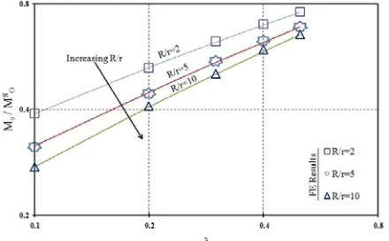
Fig. 11 shows a comparison between the published formulas and the current FE analysis. This comparison shows good agreement with Kim et.al closed formula. The results in Fig. 12 are in a log-log scale and hence the predications by Kim et.al are linear. Finally Fig. 11 and Fig. 12 show that the limit moment does not depend only on the bend characteristics but it is additionally dependent on either on r/t or R/r .
Table 2 Comparison between the experimental results, published works and current FE analysis for limit load determination
Material R / r r / t Temp.
οCy
σ (Mpa) σu(Mpa) εo(% ) Exp( )
o
M KN.m MExpo MCo MoExp MKo
Exp
o o
M M Reference
SA106Gr B 2.88 6.176 20 322 469 0.16 20.25 1.17 1.02 1.03 [13] SA106Gr B 2.88 6.176 120 286 424 0.14 20.76 1.35 1.17 1.18 [13]
BS970 2.06 18.52 20 216 - 0.12 0.2 1.27 1.1 0.96 [20]
BS970 2.07 19.69 20 288 - 0.15 0.23 1.21 1.05 0.98 [20]
ASTM A-106B 2.09 11.34 20 273 511 0.13 23.27 1.52 1.33 1.13 [26] ASTM A-106B 2.09 11.34 20 317 469 0.14 21.92 1.24 1.08 0.93 [26] ASTM A-106B 2.14 7.171 20 238 485 0.12 41.69 1.55 1.34 1.18 [26] ASTM A-106B 2.84 11.34 20 345 507 0.17 29.83 1.26 1.1 1.07 [26] ASTM A-106B 2.91 7.171 20 261 448 0.13 48.36 1.33 1.16 1.14 [26]
ISSN 2348 – 7968
266 3.2. Internal pressure:
Based on von misses yield criteria, Goodall [31] proposed the lower bound limit pressure of elbows under internal pressure as following
s
o o 1-r R
P =P 1-r 2R
(20) Where Pos denotes the limit pressure of the straight pipe, given by
s
o 2 o r+t 2 2 o t
P = σ ln r-t 2 σ r
3
3 (21)For 90° thin walled elbow with r t >5, Kim et al. [32] proposed the following approximation for the limit pressure of pipe bend based on FE analysis
o o s
P 1
R P 1+Aexp -B
r
(22)
r 0.09 rA=1.19 t+1 -1; B=0.0013 +0.307t
The abovementioned formula was compared with the
present FE results in Fig. 13, showing good agreement with Kim et al. [32].
3.3. Combined internal pressure and In-plane
bending
ASME PBVC section III Div. I [12] determined structure failure of pipe bends under combined internal pressure and bending loads via the following equation
2 3 y
1.95M Pr +0.75xt 1.5σ
λ I (23)
The abovementioned equation was established based on small displacement analysis considering the maximum stress is a sum of membrane stress caused by internal pressure and bending stress by bending moment.
Goodall [31] was the first to propose a closed form equation of limit load of pipe bends under combined internal pressure and in-plane bending moment, based on small displacement analysis as following
o
1 3 o
o s
2 3
M 1.04λ r
1-P 2tσ
M (24)
This equation shows that the limit bending moment decreases with the increase of the internal pressure which is against the observations of Rodabaugh [33], Hilsenkopf et al. [13], Touboul et al. [20], Shalaby and Younan [34] and Chattopadhyay et al. [28]. This is due to using small displacement analysis which neglects the stiffening effect of internal pressure.
Kim and Oh [35] modified the abovementioned equation and proposed a new equation for pipe bends under combined internal pressure and in-plane bending.
os
o o
P M =
1-M P (25) Fig. 14 shows a comparison between the current FE and the above mentioned equations proposed by Goodall [31] and Kim and Oh [35].
Touboul et al. [20] proposed an equation for instability moment; defined as the maximum moment in the moment–rotation curve under combined internal pressure and bending moment as following
o
oo o
mo M 1+ 0.7 Prλ tσ 1.4-0.5 tPrσ
M P=0
.
(26)Where M P=0o
denotes the instability moment without internal pressure. The abovementioned equation did not differentiate between both modes of bending; IPC andIPO which is against the observations of Shalaby and Younan [34] and Chattopadhyay et al. [28].
Chattopadhyay et al. [36] proposed a closed form for the limit load of pipe bends under combined internal pressure and in-plane bending based on fitting of the FE results as following
For closing in-plane bending
Fig. 12 Comparison between the published formulas and the current FE analysis in terms of R/r
ISSN 2348 – 7968
267
o 2 3 2
s o
mo MM 1.122λ 0.175 -0.508PPλ (27) For opening in-plane bending
o 1 3 2
s 1.2
o
mo MM 1.047λ 0.124λP -0.5608P (28)
Applicability; 0.24 λ 0.6, 0 P 1
Recently Chattopadhyay et al. [37] developed improved equations for integrity assessment for pipe bends under combined loads; pressure and in-plane bending moment as following
For closing in-plane bending
1.418
2 3 12.129
s 0.223
o
o 2.071
mo MM 1.075λ P +8.41P λ
(29)For opening in-plane bending
1 3
s 9.6431
o 1 3
o mo -0.0617+1.0485λ M 1-P 1.2182P M +7.8509P λ
(30)R 3, , 0 1
Applicability; 2 r 5 rm t20 P
Kim and Oh [30] studied the effect of internal pressure on the PCM of pipe bends with r/t=20 and proposed the following equations
2 3
+γp
m = 1+αp +βp (31)
3 2
2
2
Where
135λ -202.5λ +101.2λ-14.575 For 0.3 λ 0.5
α= 122
For 0.1 λ 0.3 105λ -105λ+23.75
For 0.3 λ 0.5 β=
1.7
For 0.1 λ 0.3 -75λ +75λ-18.83 For 0.3 λ 0.5 γ=
-3.08
For 0.1 λ 0.3
Kim and Oh [30] suggested that the effect of internal pressure on the PCM is sensitive to the bend characteristicλ. But for pipe bends with r/t=5 and r/t =10, they found that the effect of the bend characteristic λon the PCM is less significant so they approximated the previous equations as following
3 2 2 r α=-0.18+0.07 tr r r
β=0.005 t -0.0075 t +0.0375 t -0.05
r r
γ=-0.011 t +0.110 t -0.880
2 3
+γp
m = 1+αp +βp
(32)
Also they summarized the effect of internal pressure on the
PCM for pipe bends under combined internal pressure and IPOas following
2 3
+γp
m = 1+αp +βp (33) Where
-4.4λ-3.2 For 0.2 λ 0.5 α=
3λ+1.72 For 0.1 λ 0.2
3.898λ-3.523 For 0.2 λ 0.5 β=
-12λ-0.35 For 0.1 λ 0.2
0.47λ-0.094 For 0.2 λ 0.5 γ=
16λ-3.2 For 0.1 λ 0.2
ISSN 2348 – 7968
268
4.
Effect of local wall thinning on the plastic
collapse loads for pipe bends under pure
in-plane bending
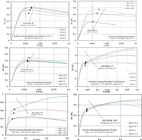
The plastic behaviour of pipe bends contains local wall thinning under in-plane bending are studied via moment-end rotation curves based on large strain FE analysis. In this section the effect of the geometrical variables of local wall thinning on the TES plastic loads was depicted in Fig. 15 and 16 for both thinning sections; extrados and intrados respectively. The extrados wall thinned section of pipe bends under IPC or intrados one under IPOis subjected to tensile stresses while extrados section under IPO or intrados one under IPC bending is subjected to compressive stresses.
The wall thinning of pipe bends is characterized with the
following parameters d/t, / πand 4 / π.
For extrados wall thinning, Fig. 15 depicts that the TES plastic loads decreases with increasing of the above mentioned parameters. Effect of thinning depth to thickness ratio d/t is less significant than circumferential thinning angle ϑ/π and longitudinal thinning angle 4ϕ/ π. It was noticed that for closing bending, the plastic instability loads are close to the TES loads and sometimes the instability load was obtained before the TES loads especially for smaller values of d/t, /πand 4 / πso the instability loads will be assumed to be the TES loads. The corresponding results of intrados wall thinning under both in-plane bending modes are depicted in Fig. 16. In comparison of Fig. 15 and 16, we see that, for the same bending mode, extrados wall thinning cases are similar to those for intrados so the effect of thinning location is
ISSN 2348 – 7968
269 minimal.
4.1 Effect of bend characteristics λ on TES
Different values of λ; corresponding to fixed value of r/t=10 leads to variable values of R/r are shown in Fig. 17 to study the effect of λ on TES plastic loads, which indicates that the TES decreases with the increasing λ or R/r. Also the effect of r/t on TES plastic loads are depicted
in Fig. 18 showing that TES plastic loads decreases with increasing r/t.
4.2 Limiting case of sufficiently long wall thinning
Oh et al. [5] studied the pipe bends with sufficiently longitudinal length of the wall thinning based on FE analysis and they found that the TES plastic loads decrease sharply with the increasing longitudinal length to a certain value of 4ϕ/π=1 which means that the wall thinning is
ISSN 2348 – 7968
270 entire the elbow and after this value, the TES plastic loads
approaches to be constant regardless the further increase of the length of the wall thinning. Hence Oh et al. [5] published the following closed formulas
L O 2 2 M dF 1 α+βλ
M t
θ θ
α=2.9 π ,β=0.29+0.9 π
(34)
Where M is given from Eq.(19) published by Kim and O Oh [30].
For intrados thinning subjected to IPO
L O 2 2 M dF 1 α+βλ
M t
θ θ
α=2.2 π ,β=0.1+2.9-3.6 π
(35)
Where M is given from Eq.(18) published by O Chattopadhyay et al. [28].
For extrados thinning subjected to IPO bending or intrados thinning subjected to IPC bending
L O
M θ d
F 1 1.8
M π t (36) Where MO is denoted from Eq. (18) and Eq. (19). Fig. 19, 20 and 21shows a comparison between the current FE results and the above mentioned formulas and it shows good agreement with the proposed solution by Oh et al. [5].
4.3 Limiting case of circumferential constant depth part-through surface cracks
In the previous subsection, we studied the limiting case of the local wall thinning where the local wall thinning is entire the whole section of the elbow and further more when exceeds to the attached straight pipe.
In this subsection we will study the other limiting case corresponding to zero longitudinal length of the wall thinning which is deemed to be a surface crack. We will study the closing bending for surface cracks; closing bending for extrados and opening bending for intrados as it is not meaningful to study the crack closure bending modes. For this issue Hong et al. [38] studied the circumferential constant depth part-through surface cracks and published the following formulas
O L O θ d1.0, -3.7 +0.324π t M
F min
M θ
+ 1.587 +1.116π
(37)For intrados surface cracks under IPO
O L O θ d1.0, -3.7 +0.324π t M
F min
M θ
+ 1.587 +1.116π
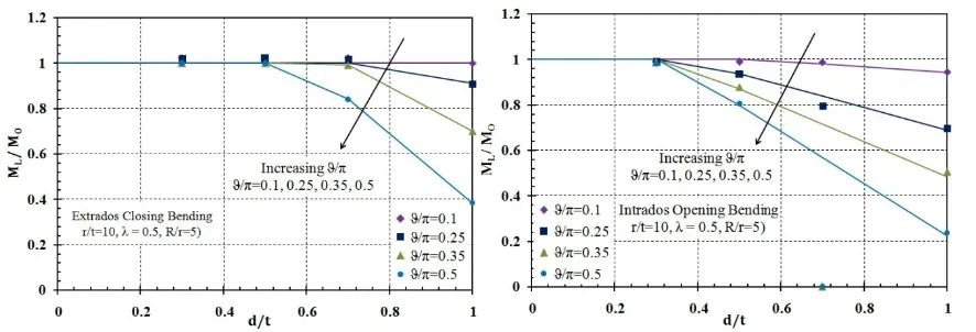
(38)Fig. 22 shows that the pipe bend can be used with surface crack up to crack depth of 0.5 of thickness for circumferential crack angle ϑ/π=0.5 which means the whole extrados section of the pipe bend but for intrados section this limit was decreased to be ϑ/π=0.3 which indicates that the intrados surface crack is more danger than the extrados one.
4.4 Effect of longitudinal extent on TES plastic loads
In the previous sub-sections, we studied the limit load solutions for two limiting cases of the longitudinal extent of local wall thinning; one for long wall thinning where thinning sections exceeds the elbow section to the attached straight pipe and the other case when longitudinal extent is zero corresponding to constant depth part through surface cracks and based on the previous observations on the behaviour of these cases, Kim et al. [6] developed the following simple approximation
o
oL O
4 4
M F -F π +F for 0 π 1 = M F (39)
Where Mo, F∞ and Fo from previous sections depending on the location of local wall thinning and bending mode.
5.
Effect of local wall thinning on limit
pressure of pipe bend
As for in-plane bending, Kim et al. [6] studied the effect of local wall thinning on limit pressure of the pipe bend according the previous mentioned limiting cases; sufficiently long wall thinning and constant depth part through surface cracks and developed a relation shows that the internal pressure tend to have constant values for sufficiently long wall thinning. They found also that the variation of circumferential angle up to ϑ/π=0.5 has a minor effect on limit pressure of wall thinned pipe bend and then they published the following relation; based on thinning depth to thickness ratio d/t only.
L o
P d
=F =
ISSN 2348 – 7968
271
Fig. 17 Effect of pipe bend characteristics λ on TES plastic loads for pipe bends with local wall thinning
ISSN 2348 – 7968
272 While the limit pressure of pipe bends with constant depth
part-through constant depth surface cracks is as following
L O
P 1
P (41)
5.1 Limit pressure of finite circumferential wall
thinning
Based on the abovementioned equations for both limiting cases, Kim et al. [6] published the a relation for the determination of limit pressure of pipe bends with wall
Fig. 19 Comparison between the FE TES loads for extrados sufficiently long wall thinning under IPC with the solution proposed by Oh et al. [5]
Fig. 20 Comparison between the FE TES loads for intrados sufficiently long wall thinning under IPO with the solution proposed by Oh et al. [5]
ISSN 2348 – 7968
273 thinning in terms of longitudinal extent as following
L o
o F F o
P = L
P d
d β=-2.76+18.3 t
exp -
β
F
(42)
5.2 Limit pressure of fully circumferential wall
thinning
Based on FE limit, Kim et al. [6] published the following relation describing the behaviour of fully circumferential wall thinning
L o
o o
2
F F
37.5
P = L
P d
d d
β=5.625-20 t t
exp -β
F
(43)
Fig. 22 Effect of circumferential part-through constant depth surface cracks on TES plastic loads of pipe bends under crack opening bending modes
Fig. 23 Effect of longitudinal extent on FE TES plastic loads for pipe bends with extrados local wall thinning under in-plane closing bending moment
ISSN 2348 – 7968
274 Where Fo is given from Eq. 40 and F∞ is denoted from the
following equation
O
L O
P 1 d d
F min 1.0, 1-t 10 +1t
P
3
(44)A compression between these relations and current FE analysis; for both finite and fully circumferential wall thinning is depicted in Fig. 26 showing that the current FE follows the same behaviour.
6.
Effect of internal pressure on limit moment
of pipe bends with local wall thinning
In the previous sections, the influence of wall thinning characteristics was discussed in case of pure in-plane bending and internal pressure only, but in fact the pipe
Fig. 25 Effect of longitudinal extent on FE TES plastic loads for pipe bends with extrados local wall thinning under in-plane opening bending moment and intrados thinning under in-plane closing moment
ISSN 2348 – 7968
275 bends subjected to combined loading, so it is necessity to
study the effect of thinning on pipe bends under combined loads. A reference case; of r/t=10 and λ=0.3 was selected for studying the local wall thinning effect on pipe bends under combined loads. Each case was compared with respect to the defect free model to show the decrease in load carrying capacity. Effect of variable thinning parameters and thinning locations were studied under both modes of in-plane bending; opening and closing.
It was noticed that for closing bending mode the limit moment increases with the increase of applied internal pressure up to a certain limit and then decreases but for opening bending moment, the limit moment decrease with the increase of applied pressure. This is due to stiffening effect of internal pressure which open the pipe bend and opposing the closing bending mode. For opening bending the internal pressure opens the bend which helps opening bending mode as shown in Fig. 27; for both thinning
location where the limit moment decreases with the increase of internal pressure. Fig. 27 depicts the effect of thinning depth on limit moment and internal pressure with respect to the defect-free model.
Fig. 28 shows the effect of circumferential angle of local wall thinning for both extrados and intrados under both bending modes; IPC and IPO where both finite and fully circumferential wall thinning was studied. Fig. 29 shows the effect of longitudinal extent on limit moment, where the extended thinning to the attached straight pipe was studied also. We can see from these figures that the variation of limit moment for different thinning depth less significant than the other thinning parameters is minimal and the limit moment for cases when thinning extends to the attached straight pipe is minimal. These observations are consistent with the previous subsections when the effect of pure in-plane bending and internal pressure was studied separately.
ISSN 2348 – 7968
276
Fig. 28 Effect of circumferential thinning angle on FE TES plastic loads for pipe bends with extrados and intrados local wall thinning under IPC and IPO moment
ISSN 2348 – 7968
277
7.
Elastic shakedown boundary of pipe bends
with local wall thinning
7.1 Theoretical background of shakedown term
The term shakedown was first introduced in the context of solid mechanics by Melan [39] through the shakedown theorem stated as follows “For a given load set P, if any distribution of self equilibrating residual stresses can be found (assuming perfect plasticity) which when taken together with elastically calculated stresses, constitute a system of stresses within the yield limit, then P is a lower bound shakedown load set and the structure will shakedown”. It is essential to determine the limit load. Being within the plastic region, it is essential to determine the shakedown limit load for structures subjected monotonic loading or in other hand, it is essential to determine the shake down limit load for components subjected to cyclic loading. Exceeding the limit load will result in failure due to gross of plastic deformation or plastic instability, while exceeding the elastic shakedown limit will result in one of two ductile failure modes which are reversed plasticity or ratcheting. When the structure is said to be shaking down, it means that it behaves fully elastically after a limited permanent amount of elastic strain in the first loading cycles. Reversed plasticity means that the structure will have plastic strain by the end of loading which is completely reversed by the end of unloading. More ever, the structure will fail after a certain number of cycles because of low cycle fatigue. The other failure mode is called ratcheting which means that the structure will accumulate plastic strain during each loading
and unloading cycle until exhausting ductility and then reaches collapse. Bree proposed a generalized interaction diagram shown in Fig. 30 showing the safe and unsafe working regions. The safe region that corresponds to elastic boundary, elastic shakedown boundary and limit loads are different within the diagram as well as the different failure mechanisms encountered when exceeds the aforementioned limits.
Researchers developed different techniques to obtain the shakedown boundary via elastic techniques with the aid of FE method to find a quick and appropriate shakedown limit load.
One of the most commonly used techniques; known as ECM elastic compensation method, was first introduced by Marriott [40], developed by Dhalla [41], Seshadri [42] and Chen and Ponter [43]. The ECM was widely used due to its simplicity in obtaining the elastic and residual stresses fields required for the lower bound shakedown limit load, but it strongly dependant on the FE meshing. Chen and Ponter [43] proposed the linear matching method LMM and recently Abdalla et al. [1] developed a direct non-cyclic numerical technique; named the simplified technique. This technique was verified against one of classical shakedown bench mark problems, known as the Bree cylinder. Fig. 31 shows the analytical shakedown boundary of Bree cylinder and a comparison with this analytical solution using the simplified technique is depicted in Error! Reference source not found..
Abdalla et al. [44] extended using the simplified technique to a long radius smooth pipe bend subjected to internal
Fig. 30 Bree diagram showing the safe and the unsafe operating regions
ISSN 2348 – 7968
278 pressure and cyclic bending moments. In the current study
we will enlarge using this technique to study the effect of local wall thinning of pipe bends under combined internal pressure and cyclic in-plane bending moments.
7.2 The simplified technique for determination of
elastic shakedown boundary
The simplified technique is a direct non-cyclic numerical technique. It consists mainly of two consecutive analyses; the first analysis is an elastic analysis represents unloading and this analysis is conducted by applying the cyclic monotonic load only without exceeding the yield stress of the pipe while the second analysis step is an elastic perfect plastic analysis which involves applying the constant internal pressure and the cyclic bending moment. The internal pressure is applied in the first step and causes only elastic stresses in the pipe bend, and then the bending moment is applied monotonically in the second step in an increasing manner causing the pipe bend strain to exceed the material yield strain.
By applying the two analyses and extracting their results, the residual stress is calculated for every element in the pipe bend structure at every solution increment (i) as following
i
i i ref
r ELPL M
σ =σ EM
(45)
Where
i
r
σ is the von-misses equivalent residual stresses,
i
M is the bending moment magnitude at the increment (i) in the elastic plastic solution. The term (M ) denotes the ref
reference cyclic bending moment applied in the first elastic step causes elastic stresses in the pipe bend. The residual stresses (
i
r
σ ) scaled to the same bending moment load increment M by subtracting the elastic stress i
components from the elastic plastic stress (
i
ELPL
σ )
component at every elastic plastic solution increment (i). A computer program is developed to read the output data of both the elastic and elastic plastic analysis to calculate the residual stress components for all elements at every elastic plastic solution increment (i) as following
x y y z
1
r 2
z x x y z
2 2
r r r r
1
eq 2 2
2 2 2
r r r r r
σ σ σ σ σ = σ σ σ τ τ τ
-
+
-
(46)Where the terms
x r σ , y r σ , z r σ , x r τ , y r
τ and
z
r
τ are the
residual stress components calculated according to Eq. (45).
Error! Reference source not found. depicts the elastic
and shakedown boundaries for pipe bend with local wall thinning at extrados and intrados closing and opening bending moments. For the extrados wall thinning it is noticed that the shakedown boundaries for closing bending are higher than those for opening bending, while the shakedown boundaries of intrados thinning is the least one indicating the danger and the probability of failure of intrados thinning.
A reference case of rm/t=10, λ=3 and θ/π=0.5 was selected to determine the elastic shakedown boundary. When we studied the effect of circumferential angle θ/π, we found that the highest elastic stress value was at crown, so the elastic shakedown boundaries are almost the same; for lower pressure with respect to the defect free case. This can be approved from determination of average von-misses stress over the circumference of the elbow as depicted in Fig. 33.
Fig. 33 depicts the elastic and shakedown boundaries for the abovementioned case. Both factors; the thinning depth and longitudinal extent for extrados closing bending and intrados opening bending is shown in Error! Reference Fig. 32 Comparison between the analytical solution and FE solution via
the simplified technique for the Bree cylinder problem
ISSN 2348 – 7968
279
source not found., where thinning depth affects the
shakedown boundaries higher than the longitudinal extent. For lower pressure, the variation in elastic shakedown boundaries due to variation of thinning longitudinal extent is minimal.
In order to be sure of the obtained boundaries, a full elastic plastic analysis has been implemented on pipe bend with extrados wall thinning at three positions shown in Fig. 35. Fig. 36 shows the full elastic plastic loading that has been implemented on the full elastic plastic analysis.
The analysis contains four repeated in-plane bending moment cycles and the steady pressure loading added in a separate step.
Fig. 34 Elastic and shakedown boundary limits for pipe bends with local wall thinning at extrados and intrados under in-plane opening and
closing bending moments
Fig. 35 Elastic and shakedown boundary of pipe bends with local wall thinning at extrados under IPC moment
Fig. 36 loading during the full cyclic elastic plastic analysis
ISSN 2348 – 7968
280
8.
Conclusions
Three dimensional, geometrically non-linear elastic-plastic finite element analyses were performed on pipe bends with internal local wall thinning subjected to pure in-plane bending only, internal pressure only and combined in-plane bending and internal pressure to investigate the effect of local wall thinning parameters on the integrity of elbows. The effect of local wall thinning parameters such as thinning depth, circumferential angle, longitudinal extent and thinning location, on the plastic collapse behaviour were investigated.
Two limiting cases of local wall thinning corresponding to sufficiently long wall thinning and zero longitudinal length wall thinning corresponding to constant depth part through surface cracks were considered. The TES plastic loads have no longer dependency on the axial longitudinal extent.
Shakedown domains for locally thinned elbows were obtained via a non-cyclic numerical technique were obtained and full cyclic elastic plastic analyses were done to gain confidence for the obtained boundaries. The shakedown boundary for locally thinned elbow; where the thinning did not exceed the crown surface is almost the same with the defect free elbow at low internal pressure and it is affected with the increasing pressure.
References
[1] Abdalla HF, Megahed MM et al.Younan MYA. A Simplified Technique for Shakedown Limit Load Determination. Nuclear Engineering and Design. 2006;237:1231-40.
[2] API Standard 579-1/ASME FFS-1, 2007, “Fitness-For-Service”.
[3] Oh CK, Kim YJ et al.Park CY. Effects of local wall thinning on net-section limit loads for pipes under combined pressure and bending. Nuclear Engineering and Design. 2009;239:261-73.
[4] Kim YJ, Oh CK, Park CY et al.Hasegawa K. Net-section limit load approach for failure strength estimates of pipes with local wall thinning. International Journal of Pressure Vessels and Piping. 2006;83:546-55.
[5] Oh CS, Kim YJ et al.Park CY. Plastic loads of elbows with local wall thinning under in-plane bending. Int J Fract. 2007;145:63-79.
[6] Kim YJ, Kim J, Ahn J, Hong SP et al.Park CY. Effects of local wall thinning on plastic limit loads of elbows using geometrically linear FE limit analyses. Engineering Fracture Mechanics. 2008;75:2225-45.
[7] Oyamada K, Konosu S et al.Ohno T. Development of A Plastic Collapse Assessment Procedure in the P-M Diagram Method for Pipe Bends With A Local Thin Area under Combined Internal Pressure and External In-Plane Bending Moment. Nuclear Engineering and Design. 2012;247:42-57. [8] ABAQUS Version 6.10-1 User’s manual.Inc.and Dassault
Systemes; 2010.
[9] Prabhakaran KM, Srivastava A et al.Ghosh AK. Plastic collapse moment of 90° long radius elbows with internal circumferential surface crack at intrados under in-plane bending. International Journal of Pressure Vessels and Piping. 2011;88:269-80.
[10]Gerdeen JC. A critical evaluation of plastic behavior data and a united definition of plastic loads for pressure components. WRC Bull. 1979;254.
[11]Robertson A, Li H et al.Mackenzie D. Plastic collapse of pipe bends under combined internal pressure and in-plane bending. International Journal of Pressure Vessels and Piping. 2005;82:407-16.
[12]ASME (American Society of Mechanical Engineers), 2007. Nuclear Components. ASME B&PV Code Sec.III.
[13]Hilsenkopf P, Boneh B et al.Sollogoub P. Experimental study of behavior and functional capability of ferritic steel elbows and austenitic stainless steel thin-walled elbows. International Journal of Pressure Vessels and Piping. 1988;33:111-28.
[14]Wilkins K. Experimental and Analytical Investigation into the Non-Linear Behavior of 2" and 4", 90 degree, Large Radius, Schedule 10, Stainless Steel Elbows Under Monotonic, Cyclic and Rate Dependent Loading, PhD. North Carolina State University; 2002.
Fig. 38 Reversed plasticity behaviour of pipe bend with local wall
ISSN 2348 – 7968
281 [15]Tan Y, Wilkins K et al.Matzen V. Correlation of test and
FEA results for elbows subjected to out-of-plane loading. Nuclear Engineering and Design. 2002;217:213-24.
[16]Marcal PV. Elastic–plastic behavior of pipe bends with in-plane bending. J Strain Anal. 1967;2:84-90.
[17]Spence J et al.Findlay. Limit load for pipe bends under in-plane bending. 2nd International Conference on Pressure Vessel Technology. San Antonio1973. p. 393-9.
[18]Calladine C. Limit analysis of curved tubes. J Mech Eng Sci 1974;. 1974;16.
[19]Goodall I, Large deformations in plastically deforming curved tubes subjected to in-plane bending. Research Division Report RD/B/N4312. UK:: Central Electricity Generating Board; 1978.,
[20]Touboul F, Djedidia MB et al.Acker D, 1989, "Design criteria for piping components against plastic collapse: application to pipe bend experiments," Cengdian Liu Nichols RW, eds., Beijing, pp. 73-84.
[21]Griffiths JE. The effect of cracks on the limit load of pipe bends under in-plane bending: Experimental study. International Journal of Mechanical Sciences. 1979;21:119-30.
[22]Miller AG. Review of limit loads of structures containing defects. International Journal of Pressure Vessels and Piping. 1988;32:197-327.
[23]Zahoor A. Ductile fracture handbook: Novotech Corp; 1991. [24]Marie S,Chapuliot S,Kayser Y,Lacire MH, et al. French
RSE-M and RCC-MR code appendices for flaw analysis: presentation of the fracture parameters calculation—part IV,cracked elbows.Int J Pres Ves Piping 2007; 84:659–86. [25]Drubay B, Marie S et al.Chapuliot S, A16: Guide for Defect
Assessment and Leak-Before-Break Analysis; 1995, Third Draft, Atomique Commissariat A L’energie, France. [26]Greenstreet WL, Research USNRCOoNR, Laboratory ORN
et al.Energy USDo. Experimental Study of Plastic Responses of Pipe Elbows: Oak Ridge National Laboratory; 1978.
[27]Chattopadhyay J, Dutta BK, Kushwaha HS, Mahajan SC et al.Kakodkar A. Limit load analysis and safety assessment of an elbow with a circumferential crack under a bending moment. International Journal of Pressure Vessels and Piping. 1995;62:109-16.
[28]Chattopadhyay J, Nathani DK, Dutta BK et al.Kushwaha HS. Closed-Form Collapse Moment Equations of Elbows Under Combined Internal Pressure and In-Plane Bending Moment. Journal of Pressure Vessel Technology. 2000;122:431-6.
[29]Chattopadhyay J, Tomar AKS, Dutta BK et al.Kushwaha HS. Closed-Form Collapse Moment Equations of Throughwall Circumferentially Cracked Elbows Subjected to In-Plane Bending Moment. Journal of Pressure Vessel Technology. 2004;126:307-17.
[30]Kim Y-J et al.Oh C-S. Closed-form plastic collapse loads of pipe bends under combined pressure and in-plane bending. Engineering Fracture Mechanics. 2006;73:1437-54.
[31]Goodall IW, Lower bound limit analysis of curved tubes loaded by combined internal pressure and in-plane bending moment, 1978, CEGB report RD/B/N4360, Board Central Electricity Generating, France.
[32]Kim YJ, Je JH, Oh CS, Han JJ et al.Budden PJ. Plastic loads for 90° thick-walled elbows under combined pressure and
bending. The Journal of Strain Analysis for Engineering Design. 2010;45:115-27.
[33]Rodabaugh EC. Interpretive report on limit load analysis and plastic deformations of piping products. Weld Res Counc Bull. 1979;254:65-82.
[34]Shalaby MA et al.Younan MYA. Limit Loads for Pipe Elbows With Internal Pressure Under In-Plane Closing Bending Moments. Journal of Pressure Vessel Technology. 1998;120:35-42.
[35]Kim Y-J et al.Oh C-S. Limit loads for pipe bends under combined pressure and in-plane bending based on finite element limit analysis. International Journal of Pressure Vessels and Piping. 2006;83:148-53.
[36][36] Chattopadhyay J, Kushwaha HS et al.Roos E. Some recent developments on integrity assessment of pipes and elbows. Part I: Theoretical investigations. International Journal of Solids and Structures. 2006;43:2904-31.
[37]Chattopadhyay J, Kushwaha HS et al.Roos E. Improved integrity assessment equations of pipe bends. International Journal of Pressure Vessels and Piping. 2009;86:454-73. [38]Hong S-P, Kim J-H, Kim Y-J et al.Budden PJ. Effect of
internal pressure on plastic loads of 90° elbows with circumferential part-through surface cracks under in-plane bending. Engineering Fracture Mechanics. 2010;77:577-96. [39]Melan E. Theorie Statisch Unbestimmter Systeme Aus Ideal
Plastischean Baustoff. Sitzber. Akad. Wiss. Wien IIa. 1936;145:195-218.
[40][40] Marriott DL. Evaluation of deformation or load control of stresses under inelastic conditions using elastic finite element stress analysis. Transactions of the ASME -PVP Division. 1988;136:3-9.
[41]Dhalla AK. Simplified procedure to classify stresses for elevated temperature service. Transactions of the ASME -PVP Division. 1987;120:177-8.
[42]Seshadri R. Generalized local stress strain (Gloss) analysis. Theory and applications. ASME Journal of Pressure Vessel Technology. 1991;113:219-27.
[43]Chen HF et al.Ponter ARS. Shakedown and limit analyses for 3-D structures using the linear matching method. International Journal of Pressure Vessels and Piping. 2001;78:443-51.