Optimal Approach for Bus Voltage Control
with zero distortion
P.S .Choudhary
1, Aaditya .P. Agarkar
2Associate Professor, Dept. of EEE, PRMCEAM, Badnera-Amravati, Maharashtra, India 1
PG Student [EEE], Dept. of EEE, PRMCEAM, Badnera-Amravati, Maharashtra, India 2
ABSTRACT:In this paper we Described review method for bus voltage control with zero distortion. It provides detail analysis of how system works for less power consumption. The bus voltage controller must filter this ripple, while regulating the bus voltage efficiently during transients, and must therefore balance a tradeoff between two conflicting constraints, low-harmonic distortion and high bandwidth. This paper analyzes this tradeoff, and proposes a new control method for solving it without using addition hardware. Instead of reducing the distortion by lowering the loop gain, the new controller employs digital FIR filter that samples the bus voltage at an integer multiple of the second harmonic frequency. The filter presents a notch that moves the second harmonic ripple, enabling a design that operates with zero distortion and high bandwidth simultaneously, ands suitable for inverters with small bus capacitors. The proposed controller is tested on a micro inverter prototype with a 300-W photovoltaic panel and a 20-μF bus capacitor
KEYWORDS: Bus capacitor, dc bus, three phase voltage-source inverter (VSI), harmonic distortion, micro inverter, photovoltaic, solar.
I. INTRODUCTION
In comparison to other photovoltaic (PV) architectures, a main advantage of the microinverter architecture is flexibility and modularity. For this reason, these devices have been gaining popularity, especially at small urban installations, where modularity and individual maximum power point (MPP) tracking are an advantage. Each microinverter is connected to a single PV source and directly to the ac line so they are easy to install, and can track the MPP of their adjacent PV sources. In addition, the microinverter architecture is tolerant to failures, because any single failure does not disproportionately reduce the output power of the system [4]. A common topology for microinverter is the two-stage topology shown in Fig. 1. Typically, the first two-stage tracks the MPP of the source, and boosts the low input voltage, providing suitable high voltage for the second stage. The second stage generates the ac that is injected to the ac line, a current that is typically synchronized to the line voltage. The capacitor between these stages, the bus capacitor, is an internal energy storagedevice [7].
Figure 1:. Two-stage single-phase microinverter with an intermediate high voltage bus capacitor.
Figure 2: Basic bus voltage feedback loop.
II. METHOD OF POWER LINE DISTORTION
Most adjustable frequency drives operate by using a bridge rectifier to convert the incoming AC voltage to DC voltage (see figure 3). An inverter in the drive then converts the DC voltage into a precise output voltage and frequency to control the speed of the motor.
Figure 3: General block diagram of an adjustable frequency drive.
bus capacitor bank is then used to filter out the AC ripple.
Figure 4: Diode bridge rectifier on a PWM drive.
While this results in a very efficient drive, it can cause disturbances on the AC power line due to the way the drive draws AC current. Current cannot flow from the rectifier into the DC bus until the input voltage is greater than the DC bus voltage.
III. EFFCTS OF POWER LINE DISTORTION
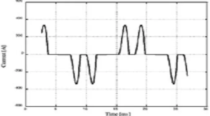
On three phase systems, the actual current to an adjustable frequency drive flows in two pulses that are 60o apart. For line 1, one pulse occurs when the voltage difference between L1 and L2 is at maximum. A second pulse occurs when the voltage difference between L1 and L3 is at maximum. The actual input current to a typical drive, or other similar electronic equipment, is shown in figure 6. These short duration, high peak current pulses can cause a number of problems to the rest of the building’s electrical systems.
therefore, enables evaluation of dynamic phenomena, such as stability and transients. This model also provides a framework for designing a suitable loop compensator. A main challenge toward a linear model is that the bus voltage
loop is not linear and not time invariant, because several key signals include harmonic components that are synchronized to the ac line. For example, the output current is generated by a multiplication of the amplitude signal
with a reference sinusoidal signal, an operator that is not time invariant and is modelled by convolution in the frequency domain. Another challenge emerges from the dynamics in the bus capacitor voltage, which are governed by
the output power, a signal that is generated by the multiplication of the sinusoidal output current and voltage. Due to these nonlinear operators, a direct analysis of the loop leads to a dynamic model that is highly complex and inefficient. To overcome such complexities, a simpler approach is to model the interactions between signals that are averaged over
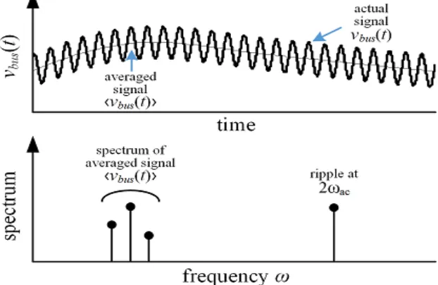
half a line cycle . This approach is useful because it leads to a simple model that predicts the major dynamic phenomena in the system. Several key signals in the bus voltage loop may be expressed as a sum of a slowly changing
average signals, and a harmonic component at 2ωac. For example, a typical spectrum of the bus voltage Vbus(t) is shown in Fig. 8. It includes low frequency components, which correspond to the slowly changing average voltage, and
a second harmonic component at 2ωac, which describes the ripple. The second harmonic
Figure 6:. Spectrum of the bus voltage signal, showing the low-frequency components and the second harmonic ripple.
V. EXPERIMENTAL RESULTS WITH A MICROINVERTER PROTOTYPE
Figure 7:. Dynamics of a stable compensator (left), with phase margin of +55°, and unstable compensator (right), with phase margin of −2.3°. In the scope images: Vpv is the input PV voltage, iac is the (rectified) output ac, Vbus is the bus capacitor voltage, and vref is the current reference signal that is generated by the control loop.
V. CONCLUSION
A conclusion of this analysis is that both the distortion and the bandwidth are affected by one main parameter, the loop gain. To eliminate this tradeoff, this paper proposes a digital controller that operates with low distortion and high bandwidth simultaneously. Instead of reducing the distortion by lowering the loop gain or employing additional hardware for mitigating the ripple, the digital controller uses a FIR filter that samples the bus voltage at a rate that is an integer multiple of the second harmonic frequency, and presents a notch that removes the second harmonic ripple. This enables a simple and low cost design, a design that has high bandwidth, causes negligible distortion in the ac line current, can be implemented with an inexpensive microcontroller, and operates well with a small bus capacitor.
REFERNCES
[1] X.Yaosuo, C. Liuchen, S. B. Kjaer, J. Bordonau, and T. Shimizu, ―Topologies of single-phase inverters for small distributed power generators: An overview,‖ IEEE Trans. Power Electron., vol. 19, no. 5, pp. 1305–1314, Sep. 2004.
[2] S. B. Kjaer, J. K. Pedersen, and F. Blaabjerg, ―A review of single phase grid-connected inverters for photovoltaic modules,‖ IEEE Trans. Ind. Appl., vol. 41, no. 5, pp. 1292–1306, Oct. 2005.
[3] J. M. A. Myrzik and M. Calais, ―String and module integrated invertersfor single-phase grid connected photovoltaic systems—A review,‖ in Proc. IEEE Power Tech Conf., Bologna, Italy, 2003, vol. 2, pp. 1–8.
[4] Y. Xue, K. C. Divya, G. Griepentrog, M. Liviu, S. Suresh, and M. Manjrekar, ―Towards next generation photovoltaic inverters,‖ in Proc. IEEE Energy Convers. Congr. Expo., Sep. 17–22, 2011, pp. 2467–2474.
[5] S. A. Khajehoddin, A. Bakhshai, P. Jain, and J. Drobnik, ―A robust power decouple and maximum power point tracker topology for a grid connected photovoltaic system,‖ in Proc. IEEE Power Electron. Spec. Conf., 2008, pp. 66–69.