Vector Control of Induction Motor Using
Improved Z Source Inverter
Leena.K.Y1, M.Waheeda Beevi2
PG Student [Electrical Machines], Dept. of EEE, College of Engineering, Trivandrum, India1
Professor, Dept. of EEE, College of Engineering, Trivandrum, India2
ABSTRACT:Nowadays the three phase induction motors are widely used in various industry application due to simple structure, reliability, low cost and several methods available to control the speed. Vector and scalar control are the available speed control techniques. With scalar control accuracy is less in the low speed range and poor dynamic torque response. For applications requiring high dynamic performance (such as railway traction, rolling mills, cement and mining industry etc.)indirect vector control of the induction machines are quite popular because of its good dynamic response. Induction motor can be operated as separately excited DC motor by using vector control method.With vector control it is possible to decouple the torque producing and flux producing components of stator current thus dc motor like performance is possible.. The Z source inverter replaces the conventional voltage and current source inverters with its voltage buck and boost capability. The inrush current and capacitor voltage stress in the impedance network of the Z source inverter is high, therefore high rating capacitor is required. This can be effectively reduced using improved Z source inverter, which is major drawback of conventional ZSI. Vector controlled induction motor drive using improved Z source inverter is implemented in MATLAB/SIMULINK.
KEYWORDS: Z source inverter, vector control, magnetizing current, simple boost control
I. INTRODUCTION
Three phase induction motors are widely used for different application in industries. The extensive use of induction motors in industries is due to their cost effectiveness, ruggedness and low maintenance requirements. In addition to this vector and scalar speed control techniques are available for induction motors. Scalar control is aimed at controlling the induction motor to operate at steady state by varying the amplitude and frequency of fundamental supply voltage. The scalar control drive is easy to implement but provides limited speed accuracy in the low speed range and poor dynamic torque response. The principle of vector control is to separate out the components of the motor currents responsible for producing the torque and the component responsible for producing flux in such a way that they are magnetically decoupled and then control each independently in the same way as done in the separately excited dc motor. The torque component isq is controlled in a manner analogous to the control of the armature in a dc motor. The field component is isd is controlled in the same manner as the control of the field current in a dcmotor controller. Vector control methods decouple the motor current components by estimating slips peed ,which requires a proper knowledge of rotor time constant classical control systems like PI,PID control have been used together with vector control methods for speed control of IM.
The traditional induction motor drives are based on the voltage source inverter has some limitations and problems. In Adjustable Speed Drives (ASD) with VSI
The obtainable output voltage is limited quite below the input line voltage.
The upper and lower devices of same leg cannot be gated on simultaneously.
An output LC filter is needed for providing a sinusoidal voltage .
abovesaid problems. Vector controlled induction motor drive using improved Z source inverter is a cost effective and efficient drive, which can be used for number of applications where better speed control is required.
II. Z SOURCE INVERTER
Traditional Z source inverter has an X shaped impedance network which couples the inverter main circuit to the power source. The impedance network consist of two identical inductors and two identical capacitors. The impedance network provides as a second order filter and its more effective to suppress voltage and current ripples than capacitor or inductor used alone in the traditional inverter. The diode is used to prevent the reverse flow of current. Z source inverter has a shoot through zero state which is absent in conventional voltage source inverter. During shoot through period the switches of the same leg are gated together and allows the voltage to be boosted to the required value when the input dc voltage is not up to the required level. When the dc voltage is enough to produce the required voltage,the Z source inverter perform buck conversion in the same way as voltage source inverter .Thus Z source inverter performs both buck and boost operations. Fig.1 shows the traditional Z source inverter.
Fig.1 Z Source Inverter
During shoot through period the energy is stored in the inductor. This energy is then transferred in addition to the supply voltage to the load side when normal gating of the inverter switches occur.
III. IMPROVED Z SOURCE INVERTER
In improved Z source inverter the impedance network is in series with the inverter circuit. The working of conventional Z source inverter and improved Z source inverter is same. Improved Z source inverter has the following advantages over conventional Z source inverter
The voltage stress across the capacitor is less thus voltage range of capacitor and cost can be reduced.
The inrush current at startup is effectively reduced.
In the two inverter topologies the voltage and current ripples remains same .With improved Z Source inverter the voltage stress across the capacitor can be reduced. In the traditional Z source inverter, the voltage across the capacitors is given by
Vc = (1-D)Vs / (1-2D) And in the improved Z source inverter, it is given as
Vc = {D/(1-2D)}/Vs,
whereVc = capacitor voltage; D = duty ratio of the shoot through state; and Vs = supply voltage.
The above equations show that the capacitor voltage is equal to the supply voltage when D=0 in the traditional Z source inverter circuit, and in the improved model it is reduced to zero when D=0. This proves that the capacitor voltage is greatly reduced. The equivalent circuit of the improved Z-source inverter during the shoot through and non
shoot through states are shown in Fig.3 and 4. Assuming that L1 = L2 = L and C1 = C2 = C.
Fig.3 Equivalent circuit of improved Z source inverter in shoot through state
The above figure shows the equivalent circuit of improved Z source inverter in shoot through state,during which the switches of the same leg are gated together.The modelling equations are
i = (V + V )/sL V =−i /sC i = (V + V )/sL V =−i /sC
The equivalent circuit of improved Z source inverter in non shoot through state is as shown in Fig.4
Fig.4 Equivalent circuit of improved Z source inverter in nonshoot through state
The modelling equations are
a).CONTROL STRATEGY
The control strategy used here is the simple boost control. Simple boost control uses two straight lines to control the shoot through states. When the carrier wave is greater than upper envelope or lowers than lower envelope ,the circuit turns into shoot through state. Otherwise it operates just as the traditional the carrier-based PWM
IV. INDIRECT VECTOR CONTROL
Indirect vector control is very popular in high performance industrial drives. In indirect vector control, the rotor field
angle θe and unit vectors are obtained by the addition of rotor speed ωr and slip speed ωsl. In order to implement the
indirect vector control strategy, it is necessary to take the following dynamic equations into consideration
e r sl r sl
e dt dt
(1)
The rotor circuit equations are as follows:
0
r ds sl qr
r m dr r r dr i R L L L R dt d (2) 0
r qs sl dr
r m qr r r qr i R L L L R dt d (3)
For decoupling control,
qr
0
. So the total flux
r, directs on the d axis alone. Now from equations (1) & (2), weget; ds m r r r
r L i
dt d R L (4)
Also, slip frequency can be calculated as;
ds qs r r qs r r r m sl i i L R i L R L (5)
The constant rotor flux
rand 0dt
d r can be substituted in equation (4), so that rotor flux becomes;
ds m
r
L
i
(6)The electromechanical torque is explained as;
qs r r m e i L L P T 2 2 3 (7)
The block diagram of the proposed system is shown in Figure 3.Induction motor is supplied from An improved Z source inverter. The FOC is used for a decoupled motor speed and flux control with PI controllers.
V. SIMULATION RESULTS
The simulation of indirect vector control of induction motor drive using improved Z source inverter is done by using MATLAB/SIMULINK.
Table.1 Simulation parameters for improved ZSI
The voltage across the capacitor of the improved Z source inverter is as shown in Fig.6
Fig.6 Capacitor voltage of improved ZSI
Parameters Values
Power 9kW,3 phase
Voltage 440V
Frequency 50Hz
Stator Resistance .399Ω
Rotor Resistance .3107 Ω
Number of pole pairs 2
Stator Leakage Inductance 6.3mH
Rotor Leakage Inductance 6.3mH
Magnetizing Inductance .053H
Moment of Inertia 0.03kg-m2
Load Torque 57Nm
Rated speed 1455rpm
Table.2 Induction motor parameters
Parameters Value
L1= L2 11.76 Mh
C1=C2 0.0008 F
Figure 7 (a), (b) and (c) shows the speed response, torque response and stator current of the drive with a load torque at 2sec and reference speed of 1200 rad/sec. Full load condition is applied at 2sec. At t = 2 seconds, when load is applied the speed has slight distortion and catch up with the reference speed of 1200 rpm..
Fig.7(a) Speed response
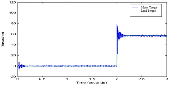
Fig.7(b) shows the torque response. When a load of 57 Nm is applied at t=2 sec the motor torque catches the load torque.
Fig.7(b) Torque response
The output stator current increases when a load is applied at t=2 sec as shown in fig 7(c).
Figure 8 shows the estimated magnetizing current value, which follows the reference current.
Fig.8 Magnetizing current
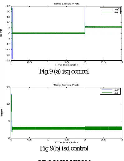
Figure 9(a) and (b) shows the combined output of actual and reference values of q axis and d axis currents.
Fig.9 (a) isq control
Fig.9(b) isd control
VI.CONCLUSION
The vector control is applied by using an improved Z Source inverter, which reduces the capacitor voltage stress thereby overcoming the demerits of conventional Z Source inverter. In the proposed method the rating of capacitor used can be reduced and hence the cost of the drive. The drive is reliable in conditions where voltage sag and swell occurs as it has both buck and boost capability. The improved ZSI can be applied to areas where the input DC voltage is unreliable or it is of highly varying in nature. This makes the improved ZSI to be used in non- conventional sources of energy such as in photovoltaic systems and in fuel cell applications in which the DC voltage can be boosted to the required value and then used in various applications. Vector control technique provides better speed and torque response. Vector controlled induction motor drive using improved Z source inverter is a highly reliable and efficient drive system and can be used in adjustable speed application.
0 0.5 1 1.5 2 2.5 3
-25 -20 -15 -10 -5 0 5 10 15 20 25
Time (seconds)
is
q
_
c
n
tr
l
Time Series Plot:
isq* isq
0 0.5 1 1.5 2 2.5 3
0 5 10 15
Time (seconds)
is
d
_
c
n
tr
l
Time Series Plot:
REFERENCES
[1] Lekshmi.H, waheedaBeevi.M“V/F control of induction motor using improved Z sourceInverter”National conference on technological trends NCTT –Aug 2014.
[2] Yu Tang, Member, IEEE, ShaojunXie, Member, IEEE, and Chaohua Zhang “Animproved Z Source Inverter”, IEEE Trans. Pow.Elec, vol. 26, no. 12, pp. 3865-3868, Dec 2011
[3] F. Z. Peng, A. Joseph, J.Wang, M. Shen, L. Chen, Z. G. Pan, E. O. Rivera, and Y. Huang, “Z-source inverter for motor drives,” IEEE Trans. Power Electron., vol. 20, no. 4, pp. 857–863, Jul. 2005.
[4] Yu Tang, Member, IEEE, ShaojunXie, Member, IEEE, and Chaohua Zhang “An improved Z Source Inverter”, IEEE Trans. Pow.Elec, vol. 26, no. 12, pp. 3865-3868, Dec 2011
[5] Z.V.Lakaparampil, K.A.Fathima : CDAC, ProfV.T.Ranganathan IISC Banglore “Design, Modeling and Simulation of vector controlled Induction motor Drive" Publication Year: 1996.