1
* Corresponding author: E-mail ID: [email protected]ABSTRACT
In Advanced Heavy Water Reactor (AHWR), the Zr 2.5 wt% Nb alloy pressure tube is joined to SS 403 end fitting through rolled joint. In order to replace the pressure tube due to degradation issues, it is necessary to detach it from the rolled joint. Shock heating of the pressure tube in the rolled joint area by induction heating followed by fast cooling and axial application of load is being pursued to achieve this objective. Various parameters like frequency, air gap, spacing between turns, heating time etc. are known to affect the heating pattern produced by induction heating. In order to optimise the various parameters involved, finite element model of the geometry has been prepared using the software COMSOL Version 3.5a. The heating module consists of various components like, induction heating coil, structural member made of SS 304 at the centre of the heating coil to apply axial load on the rolled joint assembly for detachment and ferrite core to increase magnetic flux linking with the job and to avoid heating of the structural member at centre. Coupled electro-thermal axisymmetric analysis was carried out for different time intervals up to 35 s and frequency of current from 25 kHz to 200 kHz, in steps of 25 kHz. This paper gives details of the finite element analysis and results from the parametric studies carried out.
INTRODUCTION
In Advanced Heavy Water Reactor (AHWR), the pressure tube, made of Zr 2.5 wt% Nb alloy is joined at its ends to end fitting made of SS 403 material through rolled joint. Due to degradation mechanisms associated with pressure tube, it will be necessary to replace it during the operating life of the reactor. Easy replacement of the pressure tube is a major design philosophy of AHWR. In order to achieve this objective, it is necessary to detach the pressure tube from the rolled joint. Shock heating of the rolled joint through induction heating process followed by fast cooling and axial application of load is being pursued to achieve this objective. The induction heating coil is located close to the inside surface of the pressure tube during heating and it is necessary to ensure that heat transfer to the outer end fitting is minimum to limit its increase in its temperature. The radial clearance obtained by cooling the pressure tube from high temperature will be reduced if the temperature of the end fitting increases. Various parameters like frequency, air gap, spacing between turns etc. are known to affect the heating pattern produced during induction heating. The objective of the finite element simulation of the induction heating process is to study the effect of these parameters and optimise them for the present application.
Geometry of Rolled Joint Assembly and Induction Heating Coil
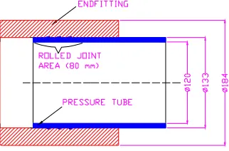
AHWR pressure tube to end fitting rolled joint area is shown in Fig. 1. The induction heating coil assembly consists of the following components:
1) Induction heating coil of diameter 9.5 mm, with non uniform gap between turns to get uniform heating pattern.
2) Structural member made of SS 304 at the centre of the assembly, necessary for applying axial load on the rolled joint assembly for detachment.
3) Ferrite core to increase magnetic flux linking with the job and to avoid heating of the structural member at centre.
2
Fig. 1 AHWR pressure tube to end fitting rolled joint.
Finite element simulation of the problem
Finite element model
Due to axisymmetric nature of the problem, only one half of the geometry has been modelled. Geometry used for modelling is shown in Fig. 2. Finite element model has been prepared using the software COMSOL Version 3.5a. The option: Electro Thermal Interaction→Azimuthal Induction Heating (Vector potential)→Transient Analysis, available with AC/DC Module of COMSOL has been used for the analysis. The finite element model used for the analysis is shown in Fig. 3. A total of 3 noded, 7017 triangular elements have been used.
Fig. 2 Geometry used for analysis.
Fig. 3 Finite element mesh.
Air
3
Thermal conductivity(W/m.K)
18.8 5 0.195 16.64+0.01436xT 24.05+9.5x10
x T
0.03
Density (kg/m3) 8000 1600 2150 6500 7640 1.128
Specific heat (J/kg. K) 475 400 1172 278+0.08205xT 450 1000
Electrical conductivity (S/m)
1.428x10⁶ 0.1 - 108/(51.54+0.1384 xT)
1.754 x 10⁶ - Relative magnetic
permeability
1 500 1 1 100 1
T is temperature in 0C.
Details of analysis carried out
Coupled electro-thermal analysis was carried out for different time intervals up to 35 s and frequency of current from 25 kHz to 200 kHz, in steps of 25 kHz. The analysis was carried out for the condition that power input to the job at all the frequencies is the same. In induction heating, for the same power input, coil current is inversely proportional to frequency¼. Hence, as the frequency was increased, coil current was reduced accordingly.
RESULTS OF ANALYSIS AND DISCUSSION
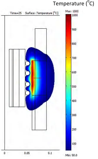
Results for a typical case of 75 kHz frequency are shown in Fig. 4 to Fig. 6.
4
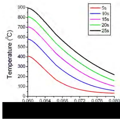
`Fig. 5 Variation of temperature with time along radial direction at 75 kHz frequency.
Fig. 6 Variation of temperature with time along axial direction at 75 kHz frequency.
Time to reach 900 0C
5
Fig. 7 Variation of time to reach 900 0C on pressure tube surface with frequency.
Radial depth of end fitting having temperature higher than 400 0C
As the frequency increases, there will be reduced heat transfer to outer end fitting, leading to its lower average temperature. Variation of radial depth of end fitting from inside surface over which temperature exceeds 400 0C is shown in Fig. 8. It can be observed from Fig. 8 that operation beyond 75 kHz does not have much effect on the spread of heating zone in the end fitting.
Fig. 8 Variation of radial depth of end fitting over which temperature exceeds 400 0C with frequency.
Temperature difference across pressure tube wall
6
Surface temperature profile
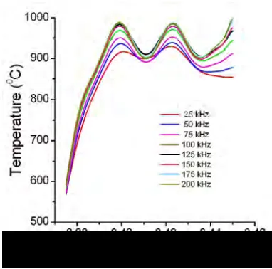
Surface temperature of pressure tube depends on the frequency of heating. It can be observed from Fig. 10 that for the same radial gap between induction coil and pressure tube surface, peaking in temperature increases with increase in frequency. Local effect of heating is more pronounced at higher frequencies.
Fig. 9 Variation in temperature difference across the thickness of pressure tube with frequency.
Fig. 10 Variation of surface temperature profile of pressure tube with frequency.
Effect of radial gap on surface temperature
7
Fig. 11 Variation of surface temperature with radial gap between induction coil and pressure tube.
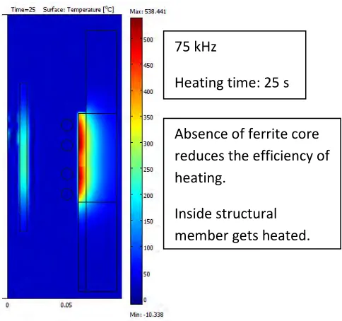
Fig. 12 Temperature distribution in the absence of ferrite.
Absence of ferrite core
reduces the efficiency of
heating.
Inside structural
member gets heated.
75 kHz
8
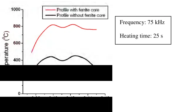
Fig. 13 Effect of ferrite core on pressure tube mid plane temperature profile.
Power requirement
In order to estimate the input power requirement to achieve the desired temperature distribution, heat generation rate corresponding to 50 kW was defined up to a depth of 2 mm of the pressure tube. A transient heat transfer analysis was carried out and it is observed that the temperature distribution is close to that corresponding to 75 kHz. With an efficiency of 80% for the inverter power supply and 45% for the coil with ferrite core, the rated power of the induction heating system is about 150 kW.
CONCLUSION
Finite element analysis of the induction heating of rolled joint assembly has been carried out using the software COMSOL. Effect of frequency of heating in the band 25 kHz to 200 kHz has been studied. Based on the analytical studies, it is concluded that the optimum frequency of induction heating in the case of AHWR pressure tube to end fitting rolled joint is about 75 kHz. The spacing between the induction heating coil turns shall be non-uniform to have uniform heating pattern. Required power input to the pressure tube is of the order of 50 kW for about 25 s to achieve the desired temperature distribution. Rated power of the induction heating system is estimated to be 150 kW. Use of ferrite core considerably increases the efficiency of heating by internal coil and also avoids the heating of structural member present inside the coil.
REFERENCES
[1] COMSOL Multiphysics Version 3.5a.