Effect of M i c r o s t r u c t u r a l A l t e r a t i o n on t h e Creep B e h a v i o u r and Effect of F l a w s in
5 0 C r 5 0 N i - N b E n g i n e e r i n g A l l o y
G. Belloni, G. Caironi, A. Gariboldi, A. Lo Conte Politecnico di Milano, Mechanical Department,
Campus Bovisa, Via La Masa 34, Milano, 1-20158 Italy. A B S T R A C T
The paper deals with 50Cr50Ni Niobium containing alloy, which is used for some components operating at elevated temperatures under corrosive conditions. When this alloy is subjected to temperature between 700 and 1000 °C, even for a short time, microstructure undergoes massive secondary phases precipitation, the alloy shows better mechanical properties, but they are associated to a considerable embrittlement. The loss of ductility, after a few hours of service, has been observed in the case the initial high temperature is kept constant and in the case the initial high temperature is subsequently lowered.
The first case is studied by means of experimental creep tests, carried out for short/medium time (100-1000 hours) on cylindrical specimens at 700 °C, at which temperature the alloy could remain for several hours during a slow heating stages of the plant, with constant load. The deformation response has been evaluated with creep constitutive equations proposed in literature for metals. On the basis of the results obtained from the previously mentioned tests, attemps will also be made to assess the influence of drop in ductility in the case of a flaw existing inside the materials at high temperature where creep strains are dominant.
I N T R O D U C T I O N
H i g h temperature c o m p o n e n t s are often p r o d u c e d by casting m e t h o d s because this production tecnique al- lows to obtain straightway almost their final shape, without the need of deformation processes, a n d allows to modify the chemical composition in view of a targeted microstructure as well as of a mechanical a n d corrosion resistance for the part. In this field, the group of high chromium-containing Ni-based alloys have been introduced for c o m p o n e n t s operating in severe environments, such as for e x a m p l e in the presence of combustion residuals. A particularly favourable combination of corrosion a n d mechanical resistance has been found for the alloy usually referred as 5 0 C r - 5 0 N i - N b [i], especially e m p l o y e d for the fabrication of pipes supports, hangers for petrochemical a n d p o w e r s t e a m plants.
A s in m a n y others high temperature casting alloys, the stay at high temperature alters the microstructure of the material, causing drastic changes in its mechanical behaviour; particularly, a drastic embrittlement. T h e observed embrittlement is due to the non-equilibrium structure in the as-cast components, fundamentally m a d e up of 7-Ni phase supersaturated in Cr a n d of a - C r primary precipitates supersaturated in Ni [i], that evolves at high tem- perature a n d a massive formation of secondary fine a - C r precipitates occurred within the 7-Ni matrix. T h e effect has been proved to be particularly deleterious w h e n the alloy is kept for several hours at 700 ° C [1,2], the lower range of the usual service conditions (700-I000 °C), but at which the c o m p o n e n t m a y be held for s o m e time during the slow heating stages of the plant. T h e loss of ductility is deleterious not only at the service temperatures, but also w h e n the c o m p o n e n t is cooled d o w n to r o o m temperature, since dangerous tensile stresses m a y arise during cooling a n d shook loading m a y occur during repairing operation of the plant.
U n d e r such kind of evolution of the material properties, it is of particular interest to define the role of mi- crostructural alterations on the mechanical characteristics, at r o o m and at high temperature. D u e to the material brittleness after the stay at high temperature it is important also to check w h a t are the changes in its hot defor- m a t i o n behaviour, a n d their effects w h e n a defect in the c o m p o n e n t causes local stress increases.
W i t h i n a research investigation on the above topics, the present study has been focused on the creep characteris- tics of the 5 0 C r - 5 0 N i - N b alloy in the as cast a n d in the heat treated conditions, during the primary a n d secondary creep stage, a n d to their correlation to the microstructural evolution of the alloy.
SMiRT 16, Washington DC, August 2001 Paper # 1546
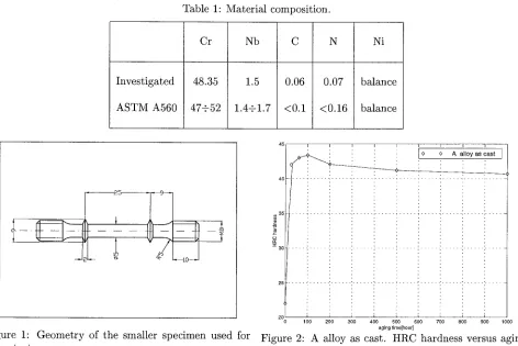
Table 1: Material composition.
Investigated
Cr Nb
48.35 1.5
ASTM A560 47+52 1.4+1.7
C N Ni
0.06 0.07 balance <0.1 <0.16 balance
-- 2 5
Figure 1: Geometry of the smaller specimen used for creep tests.
4 5 I I I I I I I
! i o_ o A alloy a__ss cas.~t
°I1 ....
...
...
~
3 5 . . . . -~ . . . ', . . . i . . . ', .. . . ; . . . ~ . . . ', . . . ', . . . ', .. . ."" 30 ... ~ ... : ... : ... , ... i ... ", ... : : ,
ii
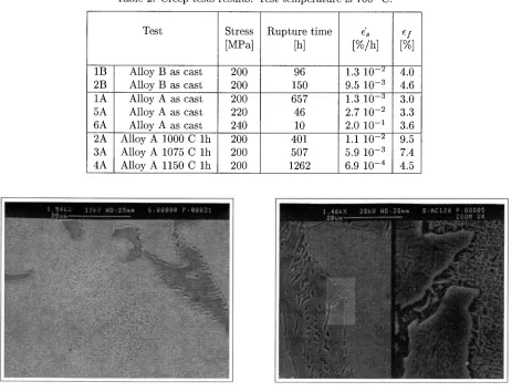
0 1 0 0 2 0 0 3 0 0 4 0 0 5 0 0 6 0 0 7 0 0 8 0 0 9 0 0 1 0 0 0 a g i n g t i m e [ h o u r ]Figure 2: A alloy as cast. HRC hardness versus aging time.
MATERIAL AND E X P E R I M E N T A L PROCEDURES
The experimental investigation has been carried out on Y-shapes block coupons obtained according to ASTM A370 standard and made of two representative heats of the 50Cr-50Ni-Nb grade. The representative chemical analysis of the alloys is given in table 1, together with the composition range specified for this grade by ASTM A560 standard. From the above coupons both samples for monitoring hardness and microstructural evolution during aging and testpieces for tensile and creep tests were machined.
Despite the fact that these alloys are usually employed in the as cast condition, a series of heat treatments at 1000, 1075 and 1150 °C for 1 hour has been performed in order to investigate the effects of different initial phase distribution, since these treatments caused the formation of coarse c~-phase precipitates within the matrix, reduc- ing the amount of the much finer precipitates of the same phase formed during maintenance at 700 °C.
The microstructure features of the alloy have been examined, after exposure at 700 °C for different periods, by using either light optical and scanning electron microscopy after etching with 10 vol. % oxalic acid water solu- tion. The morphology, size and amount of precipitates have been evaluated according to the modified DeHoff's quantitative metallography procedure, as reported in a previous paper [2]. On the same samples, HRC hardness tests were performed in order to draw the aging curves of the alloy as shown in figure 2.
Creep tests have been performed on the as cast material as well as on heat treated specimens. Creep tests have been performed either on specimens with a diameter of 5 or 10 mm and with a gauge length/gauge diameter greater than 5. The geometry of the smallest specimens is depicted in figure 1.
Test Stress Rupture time
[MPa] [h]
1B Alloy B as cast 2B Alloy B as cast 1A Alloy A as cast 5A Alloy A as cast 6A Alloy A as cast 2A Alloy A 1000 C l h 3A Alloy A 1075 C lh 4A Alloy A 1150 C l h
[%/h] [%]
200 96
200 150
200 657
220 46
240 10
200 401
200 507
200 1262
1.3 10 -e 4.0 9.5 10 -3 4.6 1.3 10 -3 3.0 2.7 10 -~ 3.3 2.0 10 -1 3.6 1.1 10 -e 9.5 5.9 10 -3 7.4 6.9 10 -4 4.5
. 4 6 i< ?: 2 ~'; !.; {) !,i [? : ,~ f.'.. ~: ~,; :5:, ;~ .'2 :[ 2 ~:? ~.', i~'.: ~...~ ~,:" . . . ;/; Y: ~3 i:~ ~:~; 4. • ~;[}4 i...:,.: :!. :?i.'.Y i~![? : 2~5.~',{~ S : i:)~i:!~.~;ii-/ii~:~ i:: : ~i~%.-;ii:.::; >
...
i iii~iiiiii~iiiii~i~i~ii~iiii!i~!i~~~i~Niiii!!!~iii{iiiii~!~iii~}~i~ii~!!!!Ni~!N~ii~!i!!!i!i~i~;~ii~ii~!~iiii!~i~!i~i!~iiii!ii!~ ... ..'.:.m..~-~:~.. < . ~ " ~ .~:i~',.':~:::-~::.-:-:..'.~ :i::~.:~s~::~:::~i ... ~:~i~::!~::.-'.-~:~:ili:~:~!i::!:i~.i:.~i:i~<,..~
~i®~! ~ ~iiii~iii:iiiiiiiii~iiiiiiiiii~:iiiii:iiiiiiiiii!i!!!ii!:~i::iiiiiii!iiiiii!!~ :: ~.~,'.-/.'.-,.~:: ~,,:-?~:~.~: ~::~ ~ ' . ~ ~ • ~ ... ~..~..-..~:., ~ ... ~ . ~ . ~ : ~ ... . ...
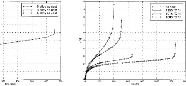
Table 2: Creep tests results. Test temperature is 700 °C.
Figure 3: A alloy aged for about 100 h at 700 °C. SEM microstructural features, left 1250x, raight 6000x.
Figure 4: B alloy aged for about 100 h at 700 °C. SEM microstructural analysis, 6000x magnification.
E X P E R I M E N T A L RESULTS
In the as cast condition the microstructure of the alloy consisted, as expected, in a 0'-Ni phase and of interden- dritic regions rich of a-Cr, these latter decorated by Nb-rich primary precipitates during aging (figures 3 and 4). The strong non-equilibrium situation caused the massive formation of secondary precipitates during aging. The microstructural evolution at 700 °C, described in previous papers [2, 3], led after about 100 hours to the presence of 67% of a - C r precipitates within the 7-matrix (figure 5). The precipitates, approximated to ellipsoids, had an aspect ratio (minor to major radius ratio) of 0.25 and a minor axis of 0.14 #m. These particles slowly coarsened during following maintenance at the aging temperature. Correspondingly, the aging curve, reported in figure 2, displayed a maximum around 100 h of aging.
In the heat treated condition coarse a-Cr precipitates were observed within the matrix. They were greater as the heat treatment temperature increased (ranging from 0.22 to 0.46 pro) and their amount, related to the equilib- rium compositions of the two phases at the heat treatment temperature, was of about 35% for heat treatment temperature of 1000 and 1075 °C and of 19% after 1 hour at 1150 °C. The presence of coarse precipitates limited the amount of the finer one formed during aging at 700 °C, as can be observed in figures 5 and 6.
::; . %::: :~; i,: :¢ 2 ~ . . ' ; ~ , ~ C ~ : 2 i a r , ~ : ? . : 0 0 i ? 0 ~ 3 P : e . ; i ~ g 0 i
• .~ i~;:..~..i¢%~!!!.~:F ~~~.!~:2.!i!!~;i~iii~!%~;7~ii!~!!i~~~:~;i~.~:~%;;~!~&~!~!~i~:!~;~i: ... !~:.~ii:i:,~:~
s~f. ~i ;::?i: ::~: : ' " ~ . : ~ . . . ?.,.~::*. : ~ " ::-: ~,~ !~i~ :::*:~::.::!!i!!!:::.::...::,"~: ~i:'::~i..: . . :" . ~ : ~ i ; " ' : !::;:.:i,i:i:i:! ..:::::;..:: •
Figure 5: A alloy heat treated at 1075 °C a n d agead at 700 °C for i00 hours. S E M microstructural analysis after creep test, 6000x magnification.
5 1 I I I
I/ . ~ i × × B a l l o y a s cast
4.5~- . . . ~ . . . . : . . . : . . . : 1 o o g a l l o y a s cast -
/
| - - : : : I ~ ~ A a l l o y a s cast
I
3 . 5 . . . " . . . : . . . : . . . ', . . . 2 . . . ; . . .
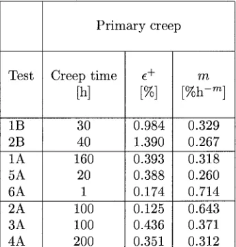
3 . . . ', .. . . ', . . . : . . . ', . . . : . . . ; . . . . ~ , . . . . . . ~ . 2 . 5 . . . ', . . . : . . . ; . . . ', . . . , . . . ; . . . 2 ... : . . . ! ... ! ... ; ... 1 " I . . . . 0.55"~- . . . :i" . . . i . . . : . . . : . . . J . . . ~ . . . i i i 0 100 200 300 400 500 600 700 time [hour] Figure 7: Creep test carried out at 700 °C and cr = 200 MPa, alloy A and B.
:, !i!iiii;ii',i',i~,:~
=,2~!!!i~5~iNiii~i
~ i !,i '~',iii'~iiiiiil
i',~ ~!', !'ii~~
Y'~NjiNN~iii!~ ~,i,: :i ! : ' ... ~ i ~:~ii;i~:,~"?? :,;~i!~i ... : i~!:;:ii!i;: :~":i;!!~iiii:i:i ii i :i!i): :!:! :i i i !iiiiiii!!!~!!:!:!!~iiii!ili!i~i~iii:i:i:iiiii:i!:!!i~::i:i:iiii :!~::~:i~i!i~:!!i~iiTi'!?: ... ;:""::;"::::::"::":::":~: ~ ... : : : ~ ... : ~ - N . . / ~ : . ~ : ! - . . . i ~:i;~:~:~%:~:~::~::~:i:~:~::~:~:~:~!!i:~::s:i~:i~i:iii~!;:.::i!!i!:: .ii~{!:::i ~i~:~;~::~::~i::.~:.::::~,~,:~.:,:~::..',:~:, ~. ~:...~:. . . ~. ; ~ : . ~ : . . . : : " ::. -r. '::~:...~::~:. ... ~ - ~...~, '.~i~::~::~-~:. ... :~: ... ~::Figure 6: B alloy heat t r e a t e d at 1000 °C and aged at 700 °C for 132 h. SEM m i c r o s t r u c t u r a l features after creep test, 6000x magnification.
lit
:: i
. . .i ascast
o o 1 1 5 0 ° C l ht
, v v 1 0 7 5 ° C l h o o 1 0 0 0 ° C l h 7 . . . : . . . ~ i . . . ', . . . : . . . : . . . : . . . " . . . ~ . . .4 . . . ', . . . ', . . . '. . . ', . . . " . . . } . . .
3 . . . , .. . . ', . . . '. . . i . . . -: . . . ~ . . .
i . . . . ... i ... : .. . . i ...
. . .
0 200 400 600 800 1000 1200 1400
time [h]
Figure 8: Creep test carried out a 700 °C and cr = 200 MPa, alloy A at different t r e a t m e n t t e m p e r a t u r e .
The detailed results of the creep tests are reported in table 2, where ~8 is the secondary creep strain rate and e/ is the creep r u p t u r e deformation, while the creep curves are shown in figure 7 and 8. Figure 7 reports the creep curve for test 1A, 1B and 2B. It can be observed t h a t the B alloy shows a similar brittle behaviour with higher p r i m a r y and secondary strain rate and shorter secondary creep t h a n A alloy. The higher p r i m a r y deformation of B alloy can be related to its shorter stay in t e m p e r a t u r e before loading. In this case the time to stay in t e m p e r a t u r e was a b o u t 6 hours with respect to a b o u t 20 hours for A alloy. While, anticipated failure in B alloy cases was reasonable correlated to the presence of some microvoids detected during metallografic investigation.
Figure 8 shows results of creep tests 1A, 2A, 3A an 4A, carried out on A alloy varying the t e m p e r a t u r e of heat t r e a t m e n t . The loss in ductility due to secondary finer precipitation during aging is shown by 2A and 3A tests, while the 4A test, related to A alloy with heat t r e a t m e n t at 1150 °C, show b o t h reduced secondary creep rate and final elongation.
C O N S T I T U T I V E E Q U A T I O N
According to viscous-viscoelastic model [4] creep d a t a for tests of table 2 can be represented by a mechanical- m a t h e m a t i c a l model in which the strain is resolved into four components:
Table 3: Creep constants for equation (3). Test t e m p e r a t u r e is 700 °C.
P r i m a r y creep
Test Creep time ¢+ rn
[h] [%] [%h -rn]
1B 30 0.984 0.329
2B 40 1.390 0.267
1A 160 0.393 0.318
5A 20 0.388 0.260
6A 1 0.174 0.714
2A 100 0.125 0.643
3A 100 0.436 0.371
4A 200 0.351 0.312
where
c e is the elastic deformation, time indipendent;
¢ p is the plastic deformation, time indipendent;
e ve is the viscoelastic recoverable deformation, time dependent;
¢v is the viscous not recoverable deformation, time dependent.
The viscoelastic and viscous components each can be represented by means of a model t h a t consist of a large n u m b e r of similar elements having a continuous spectrum of retardation times. The related time dependent strains can be closely represented by a power function of time
e v e + cv = M t N + b t "~ .
(2)
If the recoverable and non recoverable component may be represented by the same time functions, as has been found reasonably true for Aluminium alloy [4], N = rn in the equation (2) and the final form of the constitutive equation is the following:
eve + c v = ~+ t m (3)
where
c + is a c o n s t a n t d e p e n d e n t o n stress a n d o n t e m p e r a t u r e ;
rn is a constant independent on stress but dependent on temperature.
For the examined alloy, e + and rn values obtained for the best fit of the p r i m a r y and primary plus secondary creep data, in accordance with least squares, are reported in table 3. An examination of this table shows t h a t for p r i m a r y data, except for test 6A (very high stress level cr = 240 MPa) and for test 2A (high loss in ductil- ity due to heat t r e a t m e n t ) the other values of rn are very close the medium value 0.309 and the agreement with d a t a of viscous-viscoelastic model is very good, also in the case of heat t r e a t m e n t at different values of t e m p e r a t u r e .
F L A W E F F E C T
the mechanical behaviour of the material during time can play an important role in the incubation time
(ti)
of a critical crack.Reference stress method [5] may be used to define a critical strain (ec) for crack incubation t h a t integrate the effect of the transient conditions before a steady state is reached. The critical strain when steady creep conditions have been estabilished is defined as
where:
5i ec~s )
c c ( a ~ s, t~) - 0.5 C* a ~ f
6i is the critical value of the crack opening displacement;
n/n+l
= ef R (4)
C* is the creep fracture mechanics p a r a m e t e r equivalent of the J-contour integral used to describe fracture in the presence of plasticity;
aref is the reference stress;
cCef is the creep strain accumulated under the reference stress history; R is a length parameter;
n is the exponent of the deformation plasticity power law.
An i m p o r t a n t consideration, in assessing the relative importance of the incubation time (ti) to the failure time for creep damage mechanism
(tCD),
may be made approximating the accumulated creep strain as a fraction of the ductility ey. Then the equation (4) leads toti _ 0 . 5 ( _ ~ ) n / n + l
t c D -
c~
"
(5)As R, for small cracks, is the order of the crack size, for large n this equation suggests that, in the examinated cases, the failure time for creep damage mechanism governs the lifetime for crack size less of about 15-5 times (depending on the creep ductility ¢f) the crack opening displacement for incubation.
When the incubation time is closed to, or greater than, the time for continuum damage failure, as the total life cannot exceed the creep rupture time, the crack growth stage probably do not need to be examinated. In the opposite case the crack growth stage have to be considered in detail. This aspect will be investigated by means experimental test about incubation and propagation of crack.
Even if, for the examinated alloy, at the moment only a few results are know about the creep behaviour under different loading conditions at the investigated temperature, a t t e m p t will be made to assess, on the basis of the Nikbin, Smith and Webster approach [6], the influence of drop in ductility of the material, on the crack initiation and propagation in components.
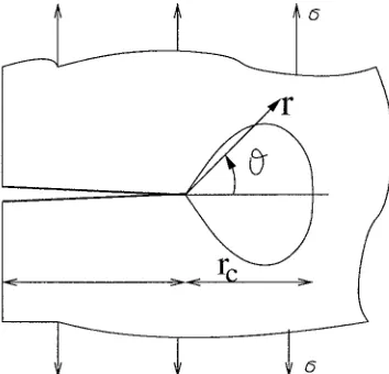
In the NSW model a process zone
(rc
in figure 9), that encompasses the creep damaged zone, is postulated at the crack tip. The time of crack initiation and the rate of damage accumulation will depend on the extension of the zone where the material show primary, secondary o tertiary creep and whether the creep ductility is constant for varying load levels present in the stress distribution ahead the crack tip. The fracture occurs when the creep ductility at the crack tip is exhausted.This model has been established for creep-ductile materials where the secondary creep dominates and creep failure strain is constant, but has been extended to deal with materials which have decreasing creep ductility with decrease in stress [6]. For the examinated material, when the massive c~-Cr precipitation occurs during the primary or early secondary creep stage and at the same time no excessive coarsening of the precipitates take place during creep, then the reduction of finally elongation could be expected. As a m a t t e r of fact the reduction of finally elongation as been observed in test of heat treated specimens, beeing greater the quantity of fine precipitates t h a t occurs at examinated aging temperature.
In order to incorporate this feature the model define an average creep strain rate (~A) on the overall creep process (primary, secondary and tertiary creep) as:
dA ~ o ( ° ) v
-- -- . ( 6 )6
Figure 9: Zone ahead of creeping crack in which damage accumulates.
lx (10.5, 240)
x
. . . "--J.~Yl ~°°)
101 10 2
rupture time [h]
Figure 10: Stress rupture plot.
Equation (6) enable to obtain the material constants, ~ - 0.00487, a0 - 198.5, p - 24.25, from rupture d a t a rather t h a n secondary creep properties. Moreover for the stress rupture plot shown in figure 10:
dcr 1 and
tr--efo (~oo) u
d - T = - " ( 7 )
then
- e s o ( 8 )
in which if p - u the constant failure strain is predicted and if p > u ductility decreas with with decrease in stress. For tests 1A, 5A and 6A of table 2 the constant u results equal 22.75 and corresponds the ductility reduction when the stress decreases.
On this basis, the d a m a g e accumulation in the NSW model results in the equation
p -Jr- 1 -- 12 ~*f---O Zp(TOe 0 r~ p + I - u ) / ( p + I ) .
(9)
where:
Ip
is a factor tabuled as function of p;e}0 is the appropriate ductility to the local state of stress at the crack tip that, due to the triaxiality of the stress field, is generally less t h a n its corresponding uniaxial value (cf0).
For the present alloy at 700 °C the equation (9) reduced to
& - 0.049 _-2;- Ip0.966
¢fo
0 . 9 0 1
rcO.O99 . (10)
W i t h this approach, therefore, crack growth rate at the same values of C* and
rc
depending on the appropriatecreep ductility e} t h a t results as function of uniaxial creep ductily (e/) and of the stress field at the crack tip. As proposed by the authors in the application of this model, for plain strain conditions, can be assumed for e} the value of of 1/50 e I and for Ip the value of 4.
Then the crack growth rate, for plain strain conditions, can be approximated by a function of C* by means of eI:
1
- 0.727 - - (C*) °~°* "c-°°99 . (11)
M o r e o v e r for rc c a n be a s s u m e d the values of a microstructural p a r a m e t e r a n d the o b t a i n e d results agree well
with Material Indipendent Engineering Creep Crack Growth Rate Assessment Diagram [6] related to NSW model. It should be pointed out that in the NSW model the value of c/ to be inserted into equations (11) should take into account the degree of constraint existing at the crack tip. Higher the constraint, higher the reduction of material ductility with respect to that observed in uniaxial creep tests. Thus, the problems of the evaluation of the actual constraint at the crack tip and of the reduction of final elongation in such constraint condition arises. To consider the limit of plain strain condition as an upper limit for the degree of constraint is a simple way to overcome there dimcult estimations of the value of e / t o be put into the above equation. On the other hand, this could be reasonably accepted for very brittle materials, such the present alloy when aged at 700 °C.
When a flaw is within an as-cast alloy not yet exposed to high temperature service, the modification of the mechanical behaviour of the material during time can play an important role in the propagation of a crack from it, analogously at the pointed out effect discuss for the incubation time. The simple NSW model can help to understand this situation. At the crack tip the occurrence of precipitates lowers the material ductility, and this is particularly evident at low stress levels when such material alteration occurs within the early primary creep stage. Thus, at high stress the material ductility is high, but reasonably also the C* value, while at low stress the material deformation is reduced, but also the value of C*, and correspondingly the crack growth rate as the incubation time. When a flaw is present in a component which has already undergone the secondary fine precipitation, the material ductility at the crack tip is heavily reduced, and, consequently the crack growth rate as the incubation time.
The obtained result is only a first interpretation of experimental data. In fact study carried out on creep-brittle alloy [7] with flaws show that the creep crack growth not be uniquelly characterized by C* and the applicable range of such fracture mechanical parameters is quite limited. Creep brittle behaviour could corresponde to crack growth where a steady state stress field has not been estabilished and non-steady state stress and damage fields, local to the crack tip, determine cracking behaviour. Consequently new experimental results and more detailed models will be need to assess the flaws effect on the studied alloy.
CONCLUSIONS
The effect of loss in ductility, due to microstructural modification, of 50Cr-50Ni-Nb engineering alloy have been investigated related its lower operating temperature of 700 °C. Mechanical and creep behaviour show a high sensitivity on temperature and time of heat treatment and on aging time. On the basis of preliminar creep test results attempt have been carried out to estimate the influence of shown loss ductility on effect of a flaw in the material.
R E F E R E N C E S
1. G.L. Swales, D.M. Ward, NACE Corrosion '79, Atlanta (USA), 1979.
2. G. Caironi, E. Gariboldi, G. Silva, M. Vedani, Second ASM Heat Treatment and Surface Engineering Confe- rence and Exibition, Dortmund, 1993.
3. E. Gariboldi, G. Caironi, High Temperature Behaviour of 50Cr50Ni Niobium Containing Casting Alloy. Pro- 4. W. N. Findley, Creep and Recovery of 2618 Aluminium Alloy Under Combined Stress with a Representation
Proceeding of 61th World Foundry Congress, Bejing, China, 1995.
5. High Temperature Component Life Assessment, Lectures Notes, Imperial College, London, 14-17 May, 1991. by a Viscous-Viscoelastic Model, Journal of Applied Mechanics, Vol. 45, September 1978, pp. 507-513. 6. K. M. Nikbin, D. J. Smith, G. A. Webster, An Engineering Approach to the Prediction of Creep Crack
Growth, Journal of Engineering Materials and Technology, Vol. 108, April 1986, pp. 186-191.
7. J. Klebanov, Constitutive equations of Creep Under Changing Multiaxial Stresses, European Journal Mecha- nics A/Solids, 18(1999), pp. 433-442.