78:11 (2016) 207–215 | www.jurnalteknologi.utm.my | eISSN 2180–3722 |
Jurnal
Teknologi
Full Paper
M
ODELLING
P
ERFORMANCE OF
O
CEAN
-T
HERMAL
E
NERGY
C
ONVERSION
C
YCLE
A
CCORDING
T
O
D
IFFERENT
W
ORKING
F
LUIDS
Norazreen Samsuri
a, Sheikh Ahmad Zaki
a*, Md Nor Musa
b,
Mohamed Sukri Mat Ali
aa
Malaysia-Japan International Institute of Technology, Universiti
Teknologi Malaysia, Malaysia
b
UTM Ocean Thermal Energy Centre, Universiti Teknologi Malaysia,
Malaysia
Article history
Received
25 May 2016
Received in revised form
16 July 2016
Accepted
18 October 2016
*Corresponding author
[email protected]
Graphical abstract
Abstract
Ocean Thermal Energy Conversion (OTEC) is a promising renewable energy technology with the concept to harness the energy stored at the surface seawater (SSW) and the cold deep seawater (DSW). The operation is based on the Rankine cycle, and involves at a minimum temperature difference of 20 K of the SSW and DSW to generate electricity. This research focuses on the economic efficiency of different working fluids used in the OTEC Rankine cycle. The various working fluids include ammonia, ammonia-water mixture (0.9), propane, R22, R32, R134a, R143a, and R410a. Most of the existing commercial OTEC systems use ammonia as the working medium despite its toxic nature. This study shows that the ammonia-water mixture still gives the best results in terms of heat transfer characteristics because of its greater transport properties and stability compared to other fluids. However, fluids such as propane and R32 can also be used as a substitute for ammonia-water mixture despite having slightly lower efficiency, because they are non-toxic and safer towards the environment. The same developmental model was used to present the proposed modified OTEC Rankine cycle, which shows a 4% increase in thermal cycle efficiency. This study reveals economically efficient and environmentally friendly working fluids.
Keywords: Ammonia, Ocean Thermal Energy Conversion (OTEC), Propane, R32, Rankine Cycle, Working Fluids
Abstrak
Lautan Terma Penukaran Tenaga (OTEC) adalah teknologi tenaga boleh diperbaharui menjanjikan dengan konsep untuk memanfaatkan tenaga yang tersimpan di air laut permukaan (SSW) dan air laut dalam sejuk (DSW). Operasi itu adalah berdasarkan kitaran Rankine, dan melibatkan pada perbezaan suhu minimum 20 K dari SSW dan DSW untuk menjana elektrik. Kajian ini memberi tumpuan kepada kecekapan ekonomi cecair kerja yang berbeza yang digunakan dalam kitaran OTEC Rankine. Cecair bekerja pelbagai termasuk ammonia, ammonia campuran air (0.9),propana, R22, R32, R134a, R143a dan R410a. Kebanyakan sistem OTEC komersial yang sedia ada menggunakan ammonia sebagai medium bekerja walaupun sifat toksik. Kajian ini menunjukkan campuran ammonia air masih memberikan hasil yang terbaik dari segi ciri-ciri pemindahan haba kerana ciri-ciri pengangkutan yang lebih besar dan kestabilan berbanding cecair lain. Walau bagaimanapun, cecair seperti propana dan R32 juga boleh digunakan sebagai pengganti untuk campuran ammonia air walaupun mempunyai kecekapan rendah sedikit, kerana ia bukan toksik dan selamat terhadap alam sekitar. Model pembangunan yang sama telah digunakan untuk membentangkan diubahsuai kitaran OTEC Rankine yang dicadangkan, yang menunjukkan peningkatan 4% dalam kecekapan kitaran haba. Kajian ini Warm Seawater Ammonia
Turbine Generator Light
Condenser Evaporator
Ammonia
Cold Seawater Pump
mendedahkan cecair bekerja ekonomi yang cekap dan mesra alam.
Kata kunci: Ammonia, Penukaran Tenaga oleh Kepanasan Laut (OTEC), kitaran Rankine, cecair bekerja
© 2016 Penerbit UTM Press. All rights reserved
1.0 INTRODUCTION
Ocean Thermal Energy Conversion (OTEC) has great potential in an area of deep ocean water where the difference in temperature between the surface water and a certain depth is large enough for an OTEC power plant to operate effectively. The initial concept proposed by Arsonval (1881) stated that the ideal temperature difference required to install an OTEC plant is greater than 20 K [1]. The plant can operate between a heat source (surface seawater at 30 °C) and heat sink (at a seawater depth of 1000 m at 4 °C) [2-4]. The development of the OTEC power plant appears to be based on the open (OC-OTEC) and closed Rankine cycles (CC-OTEC). For optimum performance of the power plant, the operation must be based on the Uehara cycle, with a mixture of ammonia and water being used as the working fluid at 5-6% thermal efficiency and a temperature difference of less than 20 K [5]. However, the use of ammonia-water mixture as the working fluid poses a high health risk [6].
For a while, Malaysia was not on any global map showing areas with the potential of generating OTEC power. However, thanks to the efforts of the
Sapura-Crest Group’s Subsidiary, Teknik Lengkap
GeoSciences Sdn Bhd in 2008 [7], a marine survey was performed in the South China Sea. This confirmed that the temperature at the bottom of the North-Borneo Trough, known as the Sabah Trough (as shown in Figure 1), is about 4 °C when compared to the surface temperature which is at about 29 °C. The above mentioned discovery gave Malaysia the opportunity to successfully operate an OTEC plant. The Sabah Trough is estimated to have a width of 60 km and a length of 100 km, with an average depth of 1000 m. It is essential to perform fundamental research in order to obtain the best possible performance of OTEC while reducing capital cost.
Figure 1 The location and area of the Sabah Trough
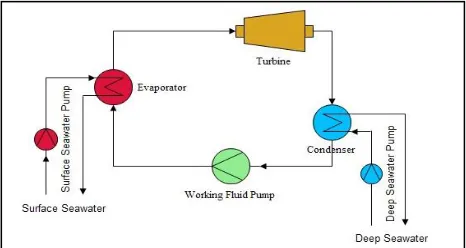
The first OTEC power plant was developed by Lennard (1987) and was based on the Rankine cycle, utilizing a low-pressure turbine because of its low operating temperature[8]. The system can be an open-cycle, a closed-cycle or a hybrid type. The closed- cycle Rankine system is the basic OTEC cycle, as shown in Figure 2. It has low efficiency and the expansion process of the saturated vapour mixture in the turbine can create liquid droplets which are known to cause damage to turbine blades [9]. The highest performance of the OTEC cycle has already been established by Uehara (1994)[10]. The Uehara cycle was developed at Saga University in Japan with a 3% higher efficiency than that of a basic closed-cycle OTEC system [11].
Figure 2 Schematic diagram of the OTEC closed Rankine cycle
deep seawater. This modification will also minimize the impact of biofouling on the inside of the tube of the heat exchanger, allowing cheaper materials to be used for manufacturing the condenser.
Figure 3 Schematic diagram of the proposed modification to the OTEC closed Rankine cycle
Additionally, further research can be carried out to simulate the performance of an OTEC cycle operating on different working fluids. The selection of appropriate working fluids can have a major effect on the overall feasibility and performance of the system [12]. A frequently used working fluid in an OTEC power plant is ammonia (or ammonia-water mixture) because its physical properties are ideal for the OTEC cycle [13-14]. However, ammonia presents some possibly fatal health risks. A vapour leak of up to 1700 ppm dosage could cause respiratory damage in human lungs, and a liquid leak making contact with the eyes or skin could lead to cold burns [15]. More than 50 working fluids have been considered in this study, but some of them were rejected because of environmental concerns and their lack of use. Finding other suitable substitutes has been a major obstacle to this research.
There is still a lack of reliable research data on OTEC technology. This study will highlights several new ideas as the objectives, such as the use of an external heat source to preheat the working fluids and replacing the working fluid with a cheaper and more environment-friendly kind.
2.0 METHODOLOGY
The OTEC theory developed in 1880s and the first demonstration model was constructed in 1930 as a benchmark that generated 22kW of electricity with low-pressure turbine[16]. To have an OTEC plant for real experiment or small-scale trials may not be desirable because it is very costly. Therefore, by using LabVIEW to build OTEC model allows us to anticipate the potential of others possible working fluids and also serve as a tool to assist design of the future plan. LabVIEW is a system designing platform developed by National Instruments which is used for
visual programming languages. Its use in various engineering fields (such as electrical, mechanical, aeronautical etc.) has contributed to the development of the biggest and most complex applications in the world in order to meet future requirements. LabVIEW provides flexibility to users via intuitive graphical programming that helps in reducing the test development time. A LabVIEW simulation is performed in five steps: requirements gathering, application architecture, development, testing and validation, and utilization, as shown in Figure 4 below.
Figure 4 The advanced application development with LabVIEW by National Instrument (2014)
The simulation was modelled over the
thermodynamic analysis of the performance of OTEC Rankine cycle. It consists of four main components: evaporator, turbine, condenser and coolant pump. Certain assumptions were made to simplify the analysis and the evaluation of the simulation [17,18]. They are given as follows:
i. Each of the components is in steady state. ii. Pressure drop and heat losses are neglected. iii. The system is fully insulated.
iv. The isentropic efficiency is given for all pumps and turbines.
The energy balance equation due to steady state condition (i.e. total energy entering a system = total energy leaving the system) is given in Equation 1.
(1)
It can further be expanded as given by Equation 2.
(2)
Where
Q
is the rate of heat transfer;m
in
and
out
m
are the internal and external mass flow rate of the system respectively;
W
in andW
out are the internal and external work of the system respectively.out in
E
E
out out
out in in
in
Q
m
W
Q
m
W
By assuming that the system is fully insulated and there is no heat loss(
Q
in= 0,Q
out= 0, andW
out=0), the energy balance equation of the pump can be written as given in Equation 3.(3)
From Equation 3, the work supplied can be expressed as in Equation 4.
(4)
The rate of heat supplied to the cycle (evaporator),
e
Q
is given by Equation 5.(5)
Rate of heat rejected from the cycle (condenser),
c
Q
is calculated by Equation 6.(6)
Where
h
out andh
in refer to enthalpy at evaporator and condenser respectively. Heat rate absorbedfrom the warm sea water,
ws e
Q
, is shown as in the Equation 7.(7)
Heat rate rejected into the cold seawater is given by Equation 8.
(8)
Where,
m
ws andm
csare the mass flow rate ofwarm and cold sea water respectively.
c
p is the specific heat capacity of seawater at constant pressure. The work done by fluid pump,wf
P
W
andturbine
W
T is given in Equations 9 and 10 respectively.(9)
(10)
Where,
h
is the enthalpy difference in the turbine system. According to Uehara and Ikegami (1990) [18], the power required to pump the working fluidPwf
P
is given by Equation 11, whereas the powerrequired for pumping warm sea water
P
ws and coldsea water
P
cs isgiven by Equations 12 and 13.(11)
(12)
(13)
Where
H
is the pressure difference. The net power output,P
n is given by Equation 14.(14)
The working fluid plays a key role in the cycle. An optimum working fluid must have the necessary thermophysical properties equivalent to its application and remain chemically stable in the preferred temperature range. The selection of working fluid affects the efficiency, operating conditions, environmental impact and economic viability of the system. The criteria for determining a potential working fluid for the OTEC closed Rankine cycle system at various conditions is explained in this section. Sami [19] have identified the important factors that influence the thermodynamic and thermophysical requirements of this system, boiling point, latent heat, specific heat, thermal conductivity, flash point, boiling temperature, chemical stability, and toxicity, as shown in Figure 5 [19].
Figure 5 Selection of working fluids by Sami [19]
In this case study, the working fluids used in the closed-cycle OTEC system had boiling points close to the operating temperature of the evaporator, which is approximately between 25 to 40 oC [20]. Additionally, the fluids have been categorized as dry, isentropic or wet according to the saturation curve
out in
in
m
m
W
in outin
m
m
W
e wfe
m
h
Q
c wf
c
m
h
Q
ws p ws ws
e
m
c
T
Q
, cs p cs cw
c
m
c
T
Q
,
)
(
P
2P
1v
m
W
P wfwf
h
m
W
T
wf
p wf wf wf Pwf
g
H
m
P
,
wf p cs ws Gn
P
P
P
P
P
(dT/ds) [21]. Dry or isentropic fluids are particularly suitable for this system. The idea of separating the fluids into categories is to ensure that they are completely superheated after isentropic expansion. This prevents liquid droplets from forming on the turbine blades.
There are two types of working fluids that can be classified as pure fluids: pure compounds and pseudo-pure fluids. The pseudo-pure fluid is a mixture of several pure compounds. In this study, ammonia, R134a, R143a, propane, and R22 were classified as pure fluids that do not mix with other compounds. R410a, R470c, R404a, R507a acted as pseudo-pure fluids for the ammonia-water mixture. Figures 6 and 7 show that the highest difference in enthalpy was found in the ammonia-water mixture, followed by pure ammonia compound, propane, and R410a.
Figure 6 Latent heat-pressure diagram of pure fluid and pseudo-pure fluid
Based on the graph in Figure 7, the amount of heat added is greater in the case of ammonia-water mixture when compared to other working fluids. This is due to its higher value of latent heat, which is the quantity of heat absorbed by a liquid to remain at a
constant temperature or pressure during
vaporization.
Figure 7 Close up Latent heat-pressure diagram of pure fluids and pseudo-pure fluids
Table 1 Fixed parameters for the study of three OTEC cycles
The simulation of the OTEC closed Rankine cycle is performed when the system is in steady state as shown in Table 1 [22-24]. Figure 8 shows the graphs that quantify the simulated model. When the reference case [23] was compared to the preliminary study, it was discovered that ammonia is the working fluid that produces the highest total work output. These findings are supported by the fact that ammonia has the highest and most suitable latent heat value for the OTEC cycle system.
(a)
(b)
Figure 8 The net work output of OTEC closed Rankine cycle using several working fluids, where (a) is developed by Yang and Yeh et al., (2014)[23]; (b) the design model simulation using LabVIEW and RefProp
Variable Value
Warm seawater inlet temperature, Twsw (oC) 30
Cold deep seawater inlet temperature, Tcsw (oC) 5
Evaporating temperature, TE (oC) 28
Condensing temperature, TC (oC) 8
Turbine efficiency, ηT(%) 0.82
Generator efficiency, ηG (%) 0.95
Warm seawater pump efficiency, ηpump,wsw(%) 0.80
Cold deep seawater pump efficiency, ηpump,csw
(%) 0.80
Working fluid pump efficiency, ηwf(%) 0.75
Pressure(kPa) Pressure(kPa)
La te nt He at (k J/k g)
SSW(oC)
This preliminary analysis also serves as an introduction to the visualization methods that was used for analysis are described in the subsequent section.
3.0 RESULTS AND DISCUSSION
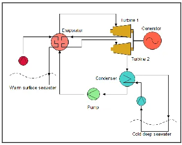
The basic OTEC closed Rankine cycle has been modified with the new idea in the objectives of this study to produce greater work output by introducing two stage steam turbines, which utilize interstage superheating and a modified cooling system utilizing cold deep seawater, regardless of the cost impact. The assumptions made about the working conditions are important factors, which must be applied to focus the analysis on the effect of adopting interstage superheating and a modified condenser cold deep seawater cooling system. The same assumption and method was used for both the basic and proposed closed Rankine cycles.
Based on the research on the OTEC closed Rankine cycle, a newly proposed cyclical system with interstage superheating was studied. In this system, the complete expansion of steam is interrupted in the high pressure turbine and steam is discharged after partial expansion. This reheated steam is supplied to a low pressure turbine for complete expansion, where the steam pressure approaches the value of the condenser pressure. The T-s diagram for the modified Rankine cycle in Figure 9 shows a slight increase in the area which is created by the introduction of reheating of steam. Thus, reheating increases the work output because of the low-pressure expansion work of the turbine. The main purpose of reheating is to protect the turbine blade by removing the moisture carried by the steam. Using two turbines also provides the advantage of improving the efficiency of the cycle, among others [25].
Figure 9 T-s diagram of the OTEC closed-cycle with interstage superheating and modified condenser cooling system
This happens mainly because a larger fraction of heat flow throughout the cycle occurs at the higher temperature of the working fluid. Moreover, the
energy of the exhaust steam and the heat gained from the warm seawater enables the production of a large amount of work. The work output of two turbines is far greater than that of a single turbine. Even Table 2 clearly shows that implementing interstage superheating leads to a 4.5% increase in the basic OTEC closed Rankine cycle. However, the disadvantage of using two stage turbines is the increase in manufacturing and maintenance costs. Hence, further discussion on the result of using different working fluids will focus on the basic OTEC closed Rankine cycle. Moreover, future studies will also emphasize the effect of using other working fluids on the economic efficiency.
Table 2 Comparison between the results of the proposed and basic closed-cycle OTEC systems using ammonia as a working fluid
Unit
Analysis of 1MW OTEC power plant
Basic OTEC Closed Rankine
Cycle
Proposed OTEC Closed Rankine Cycle
PE kPa 1099.30 1099.30 PC kPa 573.70 573.70 Qin kW 19724.40 9237.98 Qout kW 18685.00 8189.88 Wp(wf) kW 13.22 6.17 Wp(wsw) kW 96.74 43.80 Wp(cws) kW 118.76 52.05 kg/s 15.82 7.38 kg/s 1793.01 811.77 kg/s 1587.67 695.89 WT kW 905.00 756.58 Wnet kW 676.28 737.22 % 3.43 7.98
While the output of the simulated model shows a slight increase in the net power output, the efficiency of the cycle is twice of the efficiency of a basic OTEC closed Rankine cycle. Practically speaking, having two or more stages in the Rankine cycle would require significantly smaller turbines, which would decrease the efficiency [26,27]. Therefore, the model used in this study overestimates the conversion efficiencies for power output, with an increase intechno-economic efficiency at a higher number of stages. Nevertheless, this analysis proves that the proposed OTEC closed Rankine cycle can offer benefits, but with a reduction in returns.
Additionally, the system proposed in this study has also created a modified condenser cooling system. Previously, an open-loop was used for the condenser. However, the proposed system uses a closed-loop for the condenser cooling system by using ethylene glycol, which is the common working fluid in the air conditioning industry, as the chiller. Hence, it can be suggested that air conditioning technology is trying to comply with OTEC technology in this case.
The suggested working fluid uses ethylene glycol to act as the medium of heat transfer for cold seawater because it is most commonly used
wf
m
WSW
m
CSW
m
antifreeze fluid for standard cooling applications. Considering a safety factor of 20%, the cooling capacity of the system with ethylene glycol is 9569.88 kW, whereas the cooling capacity of a system using deep seawater is 10471.75 kW.
Therefore, using ethylene glycol in the proposed closed-loop condenser cooling system will decrease the cooling capacity required for the condenser. Nevertheless, the application of the proposed closed-loop condenser cooling system will minimize the impact of biofouling in the condenser tube.
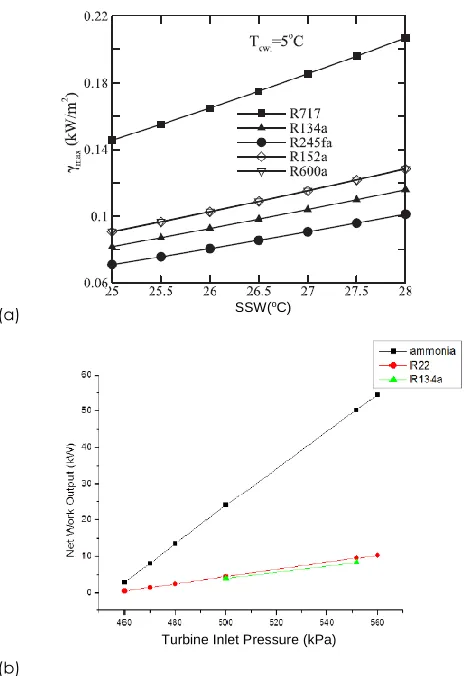
The working fluid is one of the driving factors in this study. Figure 10 shows the simulated result of net power generated by a deep seawater work pump for eight different working fluids. It can be observed that the net power generation is the highest for ammonia-water mixture (740 kW), and the power required to pump deep seawater for the cooling system is also low. The fact that pure ammonia has the second highest value of net power generation is a characteristic that is very well known in the OTEC power cycle. In this study, a working fluid must be proposed as a replacement for ammonia because it is harmful to the environment and requires a special material to maintain. Meanwhile, Figure 11 displays the result of the simulation of the performance of the cycle and its techno-economic efficiency.
Figure 10 The simulation result of net power and deep seawater work pump with 8 different selected working fluids
Figure 11 shows the relationship between the net work output and efficiency. Though both ammonia and ammonia-water mixture have higher net work output and efficiency than the other working fluids, they require a separator to ensure the turbine blade is not affected by water vapour from the fluid (especially for ammonia-water mixture). The corresponding efficiency is lower when propane and R32 are used as working fluids. Despite this, both of them possess a relatively wider range of working pressure and a more steady working range when comaped to R410a, R22, R134a, and R143a.
Figure 11 The relationship between the net work output and efficiency
The evidence from the results of the simulation shows that ammonia-water mixture has a higher value of net power produced and lower cost of main product when compared to ammonia. This still makes ammonia or the ammonia-water mixture the best working fluid in terms of net power despite its low cost efficiency. Propane has the lowest net cost of main product when compared to the other working fluids. However, the net power output of propane is still lesser than that of ammonia and ammonia-water mixture, making it the best option to replace them.
There are two types of working fluids that can be classified as pure fluids: a pure compound and a pseudo-pure fluid. In this simulation, ammonia, R134a, R143a, propane, R22, and R32 are classified as pure fluids which do not mix with other compounds. For the ammonia-water mixture, R410a acts as a pseudo-pure fluid, i.e. a mixture of several pseudo-pure compounds of fluid.
The result of the simulation shown by Figure 12 clearly displays that propane and R32 are potential fluids that can act as a replacement for ammonia. This is because they have a lower cost and are non-toxic when compared to ammonia. Propane dissolves easily in mineral oils. Additionally, as shown in Table 3, propane is a highly flammable fluid. However, this is not a significant issue in its application in OTEC closed Rankine cycle system since the highest temperature only reaches 40 oC .
R32 is the second best substitute for ammonia. It has a high value of specific heat at normal boiling point and an instantaneous effect of saturated vapour pressure on temperature. R32 is also characterized by its high productivity at cold temperature and high energy effectiveness, even if it is slightly inferior to R22 and ammonia in this properties. Propane and R32 have the potential to economically satisfy the safety and environmental requirements of the system. They are likely the best options to be used as refrigerants for the OTEC
80 90 100 110 120 130
620 640 660 680 700 720 740 760
Ammonia Ammonia-water Mixture (0.9)
R410a Propane R32
R22R134a
R143a
N
e
t Po
w
e
r (
kW
)
working fluid that will replace ammonia or ammonia-water mixture in the future.
Figure 12 Calculated result of different working fluids with respect to capital cost per net power ($/kW)
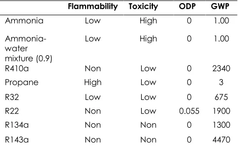
By focusing on the thermodynamic and environmental feasibility, this study has enhanced the important role of working fluid in the OTEC power cycle, as shown in Table 3.
Table 3 Environmental criteria for each working fluid by Nouman [9]
Flammability Toxicity ODP GWP
Ammonia Low High 0 1.00
Ammonia-water mixture (0.9)
Low High 0 1.00
R410a Non Low 0 2340 Propane High Low 0 3 R32 Low Low 0 675 R22 Non Low 0.055 1900 R134a Non Non 0 1300 R143a Non Non 0 4470
It is observed that the gross power of the turbine in the proposed OTEC closed Rankine cycle system decreases with a decreases in the amount of working fluid flowing into the low stage turbine. The techno-economic analysis of the next section was evaluated by using the basic OTEC closed Rankine cycle. R32 was chosen to replace ammonia as the working fluid because of its non-corrosive nature, lower toxicity and economic efficiency [9]. R32 is better suited to smaller turbines than ammonia as it helps in reducing capital cost.
4.0 CONCLUSION
The current state of the OTEC closed Rankine cycle technology was described in this paper. LabVIEW and Refprop software were successfully used to develop a model that was used for a preliminary evaluation of the performance of the system. The preliminary result of a test run involving 1 MW net power output is consistent with the existing data. This model was later used to evaluate the performance of the OTEC basic Rankine cycle using eight different working fluids. The result shows that, although none of the other fluids perform as well as ammonia in terms of thermal cycle efficiency, R32 is the best substitute for it in terms of economic efficiency.
This work was also expanded to study the performance of the proposed OTEC Rankine cycle, which was modified to include interstage reheating. The same developmental model was used to evaluate the performance of this modified OTEC Rankine cycle. The result showed that the thermal cycle efficiency increased from 3.4 to 7.9%.
Acknowledgement
This research was financially aided by the Malaysian Ministry of Education (MOE) under the Research University Grant (07J32) and is a project of the Universiti Teknologi Malaysia.
References
[1] d’Arsonval, J. 1881. Revue Scientifique. 370-372.
[2] Nihous, G. C. 2005. An Order-of-Magnitude Estimate of
Ocean Thermal Energy Conversion Resources. Journal of
Energy Resources Technology. 127(4): 328.
[3] Nihous, G. C. 2007. A Preliminary Assessment of Ocean
Thermal Energy Conversion Resources. Journal of Energy
Resources Technology. 129(1): 10.
[4] Vega, L. A., & Ph, D. (n.d.). Ocean Thermal Energy
Conversion Primer. 4: 25-35.
[5] Zhang, X., He, M., & Zhang, Y. 2012.. A Review Of Research
On The Kalina Cycle. Renewable and Sustainable Energy
Reviews. 16(7): 5309-5318.
[6] Ikegami, Y. 2010. Activity and Future Prospect Status Of
Ocean Thermal Energy Conversion - For Sustainable Energy And Water Resource. December: 1183-1186.
[7] Sapura-Crest Group’s Subsidiary TLG GeoSciences Sdn.
Bhd. 2008. Malaysia Marine Survey in The South China Sea
(MyMRS).
[8] Lennard, D. 1987. Ocean Thermal Energy Conversion-Past,
Progress And Future Prospects. Proceeding IEE. 34A: 371.
[9] Nouman, J. 2012. Comparative Studies And Analyses Of
Working Fluids For Organic Rankine Cycles - ORC.
[10] Uehara, H., Ikegami, Y., & Nishida, T. 1994. Performance
Analysis of OTEC Using New Cycle with Absorption and
Extraction Process. Proc. Of Oceanology Int.’94. 1-11.
[11] Wang, C. M., Yee, a. a., Krock, H., & Tay, Z. Y. 2011.
Research And Developments On Ocean Thermal Energy
Conversion. The IES Journal Part A: Civil & Structural
Engineering. 4(1): 41-52.
[12] Soto, R., & Vergara, J. 2014. Thermal Power Plant Efficiency
Enhancement With Ocean Thermal Energy Conversion.
[13] Wang, S., Yuan, P., Li, D., & Jiao, Y. 2011. An Overview Of
Ocean Renewable Energy In China. Renewable and
Sustainable Energy Reviews. 15(1): 91-111.
[14] Upshaw, C. R. 2012. Thermodynamic and Economic
Feasibility Analysis of a 20 MW Ocean Thermal Energy Conversion (OTEC) Power.
[15] Yuan, H., Zhou, P., & Mei, N. 2015. Performance Analysis Of
A Solar-Assisted OTEC Cycle For Power Generation And
Fishery Cold Storage Refrigeration. Applied Thermal
Engineering. 90: 809-819.
[16] Claude, G., 1930. Power from the Tropical Seas.
Mechanical Engineering. 52(12): 1039-1044.
[17] Wu, C., & Burke, T. 1998. Intelligent Computer Aided
Optimization On Specific Power Of An OTEC Rankine
Power Plant. Applied Thermal Engineering. 18(5): 295-300.
[18] Uehara, H., & Ikegami, Y. 1990. Optimization of A
Closed-Cycle OTEC System. Transaction Of the ASME Journal of
Solar Energy Engineering. 112-4: 247-256
[19] Sami S. M. 2012. International Journal Of Ambient Energy
ORC For Low Temperature Power Generation With Low GWP Refrigerants. 37-41.
[20] Gong, J., Gao, T., & Li, G. 2012. Performance Analysis of
15 kW Closed Cycle Ocean Thermal Energy Conversion
System With Different Working Fluids. Journal of Solar Energy
Engineering. 135(2).
[21] Liu, W. M., Chen, F. Y., Wang, Y. Q., Jiang, W. J., & Zhang, J.
G. 2011. Progress of Closed-Cycle OTEC and Study of a
New Cycle of OTEC. Advanced Materials Research.
354-355: 275-278.
[22] Semmari, H., Stitou, D., & Mauran, S. 2012. A Novel
Carnot-Based Cycle For Ocean Thermal Energy Conversion.
Energy. 43(1): 361-375.
[23] Yeh, R.-H., Su, T.-Z., & Yang, M.-S. 2005. Maximum Output Of
An OTEC Power Plant. Ocean Engineering. 32(5-6): 685-700.
[24] Sun, F., Ikegami, Y., Jia, B., & Arima, H. 2012. Optimization
Design And Exergy Analysis Of Organic Rankine Cycle In
Ocean Thermal Energy Conversion. Applied Ocean
Research. 35: 38-46.
[25] Sun, F., Zhou, W., Ikegami, Y., Nakagami, K., & Su, X. 2014.
Energy–exergy Analysis And Optimization Of The
Solar-Boosted Kalina Cycle System 11 (KCS-11). Renewable
Energy. 66: 268-279.
[26] Yamada, N., Hoshi, A., & Ikegami, Y. 2009. Performance
Simulation Of Solar-Boosted Ocean Thermal Energy
Conversion Plant. Renewable Energy. 34(7): 1752-1758.
[27] Kim, N. J., Ng, K. C., & Chun, W. 2009. Using the Condenser
Effluent From A Nuclear Power Plant For Ocean Thermal
Energy Conversion (OTEC). International Communications
![Figure 5 Selection of working fluids by Sami [19]](https://thumb-us.123doks.com/thumbv2/123dok_us/1345988.1167456/4.612.328.554.442.632/figure-selection-working-fluids-sami.webp)