Transactions,SMiRT-23
Manchester, United Kingdom - August 10-14, 2015
Division V, Paper ID 344
DEVELOPMENT OF EVALUATION METHOD FOR SEISMIC
ISOLATION SYSTEMS OF NUCLEAR POWER FACILITIES
-BREAK TEST OF FULL SCALE LEAD RUBBER BEARINGS FOR
NUCLEAR FACILITIES,
PART 1 OUTLINE OF BREAK TEST OF LRB OF 1.6M IN DIAMETER
-Tetsuo Imaoka1, Shinji Kosugi 2, Kenji Kanazawa 3, Takashi Nakayama4 Tomofumi Yamamoto5, Masakazu Jimbo6, and Yoshito Umeki7
1Senior Engineer , Aseismic Engineering Sec., Nuclear Plant Engineering Dept., Hitachi-GE Nuclear
Energy, Ltd, Japan
2Researcher , Aseismic Engineering Sec., Nuclear Plant Engineering Dept., Hitachi-GE Nuclear Energy,
Ltd, Japan
3Senior Research Engineer, Central Research Institute of Electric Power Industry (CRIEPI), JAPAN 4Senior Manager, Structural Engineering Nuclear Power Department, Kajima Corporation, JAPAN 5Project Manager, Nuclear system Engineering Dept., Mitsubishi Heavy Industries, Ltd., Japan 6Chief Specialist, Plant Design & Engineering Dept., Isogo Nuclear Engineering Center, Toshiba
Corporation Power Systems Company, Japan
7Manager, Nuclear Power Plant Arch. Eng. Section, Civil & Arch. Dept., Chubu Electric Power Co. Inc.,
Japan
ABSTRACT
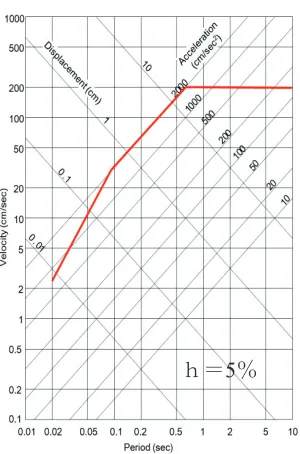
In Japan, a research and development program for seismically isolated Nuclear Power Plants was launched in 2008 as the national program entitled “Development of next generation LWRs”, partially supported by the Japanese Government. Within the program, a feasibility study had been conducted to specify and choose the best seismic isolation devices for reactor buildings. The horizontal maximum acceleration of design earthquake ground motion is 800 cm/s2. Consequently, a LRB (Lead Rubber Bearing) of 1600mm in diameter with a large lead plug type is chosen as the actual seismic isolation devices.
The diameter of
1600 mm is the largest available on the market in Japan.
For the application of the seismic isolation devices to the safety related facilities, it is important that the ultimate properties are adequately understood under beyond design basis earthquakes, and there should be carefully evaluated scale effects on the breaking strain. However, due to the capacity limitation of the test facilities, there was no data reported on the ultimate properties of LRBs of this size, and a large test machine was needed to provide the data to examine the safety margin of the LRBs. For the above reasons, the world’s largest test machine had been developed and constructed to verify the breaking strain of the LRBs experimentally.
In 2013 and 2014, break tests had been performed to evaluate the dependence of breaking strain of the LRBs under various conditions using the test machine. This paper summarizes the break test program, test results on the LRBs of 1600mm in diameter and findings. In addition, this paper presents basic properties as the design specification of the LRBs.
INTRODUCTION
“Development of evaluation method for seismic isolation systems of nuclear power facilities” has been
23rd Conference on Structural Mechanics in Reactor Technology Manchester, United Kingdom - August 10-14, 2015 Division V
a LRB of 1600mm diameter with a large lead plug was newly designed to satisfy the current design requirements for seismically isolated NPPs, and the type of rubber was changed into G4 from G6. The dimension of the LRBs is as large as possible to reduce the number of bearings required while not excessively large from a viewpoint of production.
For the application of seismic base isolation to the safety related buildings, the ultimate properties of LRBs and the seismic performance of isolation devices should be guaranteed beyond Design Basis Earthquake (DBE), and also, more careful evaluation is required in evaluation for the ultimate behavior of isolators by larger-scale experiments, because it is known that the size effect may not be neglected especially in evaluation on the ultimate property of isolators.
To investigate size effect on break strain of the full scale LRBs, the world’s largest break test machine was newly constructed, and static break tests were conducted on full-scale LRBs of 1600mm diameter designed in this project.
Isolated R/B LRB Response acc.
at base mat
Shear deformation
Lateral displacement Design
target
Less than 300cm/s2
Less thanδ e
/1.5
Less than 40cm R/B: Reactor Building
δe: elastic limit deformation of LRBs
㻌 㻌 Fig.2
Table 1 Design target Considered within this project Figure 1. Overview of seismic isolated design and break tests of full scale LRBs in this project
Figure 2. Design earthquake ground motion utilized in the seismic design of reactor buildings with
application of seismic isolation system in this project
23rd Conference on Structural Mechanics in Reactor Technology Manchester, United Kingdom - August 10-14, 2015 Division V
TEST SPECIMENS AND TEST MACHINE
Test Specimens
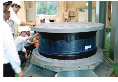
Two types of LRB of 1600mm in diameter, a large-diameter single-plug type and a multi-plug type with four plugs, are tested, as common seismic isolation systems for both BWR and PWR reactor buildings. Fig-3 shows details of single plug type LRB and multi-plug type LRB. Test specimens have an overall diameter of 1600mm, a total rubber height of 260mm and first shape factor S1 equal to 40.0. There are 26 layers of elastomer, each 10mm thick, alternated with 25 steel plates of 6.8mm thickness. The bearings were fabricated using a compound with a shear modulus G=0.4MPa, and, multi plug type LRBs and single plug type LRBs with shear modulus G=0.6MPa were also manufactured as reference specimens. The specimens were made by Japanese rubber manufactures.
Figure 3. Configuration of lead-rubber bearing for seismic isolated reactor building examined in this project
Table 1 Design specifications of full-scale LRB*1
Rubber diameter 1,600 mm Bearing load 9,000 kN Axial stress 4.8 MPa Horizontal period T2 3.41 s (2.90 s*2)
Yield seismic intensity β 0.121 Vertical frequency 16.3 Hz (17.1 Hz*2) Inner rubber 10.0 mm × 26 layers Inner steel plate 6.8 mm × 25 layers Lead plug diameter 392 mm (196 mm*3) Aspect ratio of lead plug 1.097 (2.19*3) *1: Single plug-G4 rubber type
*2: G6 rubber type, *3: Multi-plug type
(a) Single-plug type (b) Multi-plug type
Connecting Bolt
Connecting Bolt
Connecting Bolt
Connecting Bolt
Connecting Bolt Connecting Bolt
Connecting Bolt
Connecting Bolt
Lead Plug
Inner Steel Plate
Inner Rubber
Shear Key
Connecting Steel Plate
Flange Covering
Rubber
Inner Steel Plate Inner Rubber
Shear Key Connecting Steel Plate Lead Plug
Covering Rubber Flange
Hanging Bolt Hole Hanging Bolt Hole
Figure 4. Test specimen
(Lead-rubber bearing of diameter 1600mm) Table 2 Specification of lead rubber bearings for the
23rd Conference on Structural Mechanics in Reactor Technology Manchester, United Kingdom - August 10-14, 2015 Division V
Test Machine
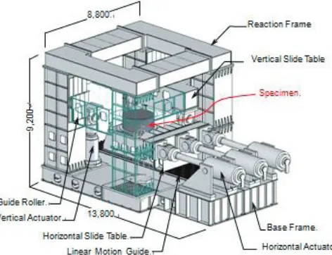
The test machine consists of an actuator assembly, a reaction frame, a hydraulic power supply and a digital control system. The maximum horizontal capacity is 25MPa with a large stroke. The maximum vertical capacity is 16MPa in compression and 9.5MPa in tension. The break test condition is not only under compression but also under tension. The test machine has a maximum displacement capacity of 0-2,200mm and a maximum loading capacity of 25.1MN in the horizontal direction. Table 3 shows the specification of the test machine, shown in Figure 4.
Table 3 Specification of the test machine
Horizontal direction
Max. load䠄kN䠅 25,100
Max. displacement䠄mm䠅 0䡚2,200㻌 *1*2
Vertical direction
Max. load Tensile
䠄kN䠅 9,500
Compressive䠄kN䠅 -16,000
Max. displacement䠄mm䠅 0䡚1,200㻌 *1 Velocity 䠄cm/s䠅 0.25 *1䠖Monotonous loading
*2䠖Alternative loading on 100% shear strain is available.
The test machine is composed of four vertical and three horizontal actuators as shown in Figure 5.㻌
Vertical force is applied by four hydraulic servo control actuators to provide various stress levels. Shear force is applied by three hydraulic servo control actuators to the horizontal slide table. The specimens are placed between the vertical and horizontal slide table. Specimens are bolted with the slide tables. Top and bottom of the specimen are bolted.
Layout of sensors is shown in Figure 6.㻌 All the loads are measured by load cells of 10MN, mounted between the end of the pistons and the slide tables. Deformation of the specimen is measured by laser type and gauge type displacement sensors. LRB surface temperature and hydraulic pressure of each actuator of the test machine are measured.
Figure 5. Schematic view of the test machine Figure 6. Layout of sensors
23rd Conference on Structural Mechanics in Reactor Technology Manchester, United Kingdom - August 10-14, 2015 Division V
TEST PARAMETERS
Basic Property Test
Static loading is repeated four times horizontally by use of a triangular wave at a loading rate of 2.5 mm/s and a displacement amplitude of ±260 mm (shear strain: 100 %) under design contact pressure (-5MPa) so as to evaluate horizontal stiffness (Kd), shear force (Qd) at 0% shear strain and equivalent damping constant (Heq) as the basic characteristics of the LRBs in the horizontal direction. To evaluate vertical stiffness (Kv), static loading is repeated four times vertically by use of a triangular wave under a variable contact pressure of ±30 % of design contact pressure under load control.
Break Tests
(1) Shear Break Tests
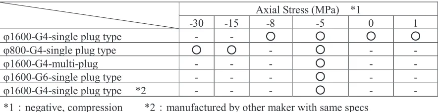
A series of shear break tests was conducted by applying horizontal force at six vertical stresses as shown in Table 4. Due to the capacity limitation of the test machine, shear breaking tests under the compression pressure at -15MPa and -30MPa are performed using a couple of 1/2 scale models. These tests are performed by controlling vertical forces.
Table4㻌 Test parameters for shear break tests of full-scale LRB
Axial Stress (MPa) *1
-30 -15 -8 -5 0 1
φ1600-G4-single plug type - - ۑ ۑ ۑ ۑ
φ800-G4-single plug type ۑ ۑ - ۑ - -
φ1600-G4-multi-plug - - - ۑ - -
φ1600-G6-single plug type - - - ۑ - -
φ1600-G4-single plug type *2 - - - ۑ - -
*1㸸negative, compression *2㸸manufactured by other maker with same specs
(2) Tensile Break Tests under offset shear strain
A series of tensile break tests was conducted by applying vertical force at five off-set shear strains of 0, 100, 200, 300, and 400% under the pressure of -5MPa as shown in Table 5. During the tensile breaking test, the machine kept the off-set shear strain. These tests were performed by applying vertical force under the horizontally off-set displacements.
Table 5 Test parameters for tensile break tests of full-scale LRB
Offset Shear Strain
0 [%] 100 [%] 200 [%] 300 [%] 400 [%]
φ1600-G4-single-plug type ۑ ۑ ۑ ۑ ۑ
φ1600-G4-multi-plug type - - ۑ -
φ1600-G6-single-plug type - - ۑ -
φ1600-G4-single-plug type 㸨 - - ۑ -
23rd Conference on Structural Mechanics in Reactor Technology Manchester, United Kingdom - August 10-14, 2015 Division V
TEST RESULTS
Tests cases
for break tests of full-scale LRB
(G4)are given in Table 6.
It was found that breakingaxial strains
with offset shear strain 200%
and 300% were smaller than those evaluated by small models in the previous study. In order to obtain more test result data, additional tensile break tests on full scale LRBs with the same large offset shear strains were carried out. The loading patterns and test number are shown in Figure 8.Table 6 Test conditions for break tests of full-scale LRBs (Rubber: G4)
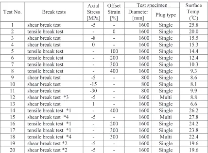
Test No. Break tests
Axial Stress [MPa]
Offset Strain [%]
Test specimen Surface Temp.
(Υ) Diameter
[mm] Plug type
1 shear break test -5 - 1600 Single 25.8 2 tensile break test - 0 1600 Single 20.0 3 shear break test -8 - 1600 Single 15.5 4 shear break test 0 - 1600 Single 15.3 5 tensile break test - 100 1600 Single 14.4 6 tensile break test - 200 1600 Single 12.4 7 tensile break test - 300 1600 Single 10.3 8 tensile break test - 400 1600 Single 9.3 9 shear break test -5 - 800 Single 8.6 10 shear break test -15 - 800 Single 8.1 11 shear break test -30 - 800 Single 9.9 12 shear break test *3 -5 - 1600 Multi 8.8 13 shear break test 1 - 1600 Single 6.6 14 tensile break test *1 - 400 1600 Single 26.2 15 shear break test *4 -5 - 1600 Multi 27.8 16 tensile break test *1 - 200 1600 Single 24.2 17 tensile break test *1 - 300 1600 Single 23.8 18 tensile break test *4 - 300 1600 Multi 22.4 19 shear break test *2 -5 - 1600 Single 19.6 20 shear break test *2 -5 - 1600 Single 19.6
*1㸸Additional tests to confirm tensile break strain with large offset strain,200%, 300%, and 400% *2㸸Reproducibility under design contact pressure
*3
㸸
four plugs type with 0 degree loading
*4
㸸
four plugs type with 45 degree loading
Figure 8. Loading patterns and Test No. Figure 7. Loading directions for multi plug
type
23rd Conference on Structural Mechanics in Reactor Technology Manchester, United Kingdom - August 10-14, 2015 Division V
Break Tests for Ultimate Property Diagram of Φ1600 LRBs
(1) Shear Break Tests
Shear break tests were monotonically conducted on eight full scale LRBs (φ1600-G4) and three half-scale LRBs under large axial stresses. Figure 11 shows tests results for the breaking conditions. All the LRBs exhibited good horizontal ductility capacity approximately corresponding to 450% shear strain, as evaluated by scale models in the previous studies. Under the tensile stress of 1MPa, shear strain at break point is 394㸣. Figure 9 shows the full-scale LRB and Figure 10 shows the LRB during test.
(2) Tensile Break Tests
Monotonic tensile break tests were performed on nine full scale LRBs (φ1600-G4) to evaluate effect of the offset shear strain on the tensile capacity. Figure 12 shows offset shear strain-axial strain relationship of tensile break tests on full-scale LRBs. Breaking axial strains with offset shear strain 200%, 300% and 400% were small with 141% or less compared with those of full-scale LRBs with offset shear strain 0% and 100%. From the results of tensile break tests, it was confirmed that breaking axial strains of all full-scale LRBs on tensile break tests were more than 11% .
Figure 12. Breaking conditions in shear strain-tensile strain plane (ȭ1600LRB, G4)
-30 -25 -20 -15 -10 -5 0 5 10
0 100 200 300 400 500
A
x
ia
l
S
tre
ss
[N
/m
m
2]
Shear Strain [%] φ1600-Single plug type (G4) φ 800-Single plug type (G4) φ1600-Multi plug type (G4)
0 100 200 300
0 100 200 300 400 500
A
x
ia
l
S
tra
in
[%
]
Offset Shear Strain [%]
φ1600-Single plug type (G4) φ1600-Multi plug type (G4) Tensile break tests
Shear break tests
Figure 11. Breaking conditions in shear strain-axial stress plane
(ȭ1600LRB, G4)
Figure 10. Photograph of full-scale LRB during test
23rd Conference on Structural Mechanics in Reactor Technology Manchester, United Kingdom - August 10-14, 2015 Division V
Hysteresis loops of㻌 Φ1600 LRBs
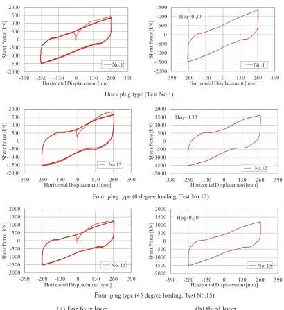
Prior to break tests, the basic property test for the LRB specimens was performed to investigate the basic performance of the specimens in horizontal and vertical directions. Figure 13 shows the results of static loading test in the horizontal direction under a contact pressure of -5MPa and a shear strain of 100 %.
The basic property is evaluated by use of the third of four loops of repetitive
loading-displacement relations. Figure 13 (a) shows all hysteresis curves (for 4 loops) of the horizontal
basic property test of the full-scale seismic isolators as a sample. The third loop is shown in
Figure 13 (b). The hysteresis loops with two different plug types are stable, and the equivalent
damping coefficient is around 0.3, although the volume of the plug is 1.5 times that of standard
LRBs in the market.
Figure 13. Load-displacement relationship of LRBs (ȭ1600, G4)
Thick plug type (Test No.1)
(a) For four loop (b) third loop
Four plug type (0 degree loading, Test No.12)
Four plug type (45 degree loading, Test No.15)
-2000 -1500 -1000 -500 0 500 1000 1500 2000
-390 -260 -130 0 130 260 390
S h ea r F o rc e [k N ]
Horizontal Displacement [mm] No.1 -2000 -1500 -1000 -500 0 500 1000 1500
-390 -260 -130 0 130 260 390
S h ea r F o rc e [k N ]
Horizontal Displacement [mm] No.1 Heq=0.29 -2000 -1500 -1000 -500 0 500 1000 1500 2000
-390 -260 -130 0 130 260 390
S h ea r F o rc e [k N ]
Horizontal Displacement [mm] No. 15 -2000 -1500 -1000 -500 0 500 1000 1500 2000
-390 -260 -130 0 130 260 390
S h ea r F o rc e [k N ]
Horizontal Displacement [mm] No. 15 Heq=0.30 -2000 -1500 -1000 -500 0 500 1000 1500 2000
-390 -260 -130 0 130 260 390
S h ea r F o rc e [k N ]
Horizontal Displacement [mm] No. 14 -2000 -1500 -1000 -500 0 500 1000 1500 2000
-390 -260 -130 0 130 260 390
S h ea r F o rc e [k N ]
Horizontal Displacement [mm] No. 14 Heq=0.33
No.12
23rd Conference on Structural Mechanics in Reactor Technology Manchester, United Kingdom - August 10-14, 2015 Division V
Basic Properties of Φ1600 LRB
Figure 14 shows the results of the basic properties, (Kd, Qd and Kv) and the design specification. The design specification line in Fig.14 are evaluated by size and physical property of rubber and lead of the LRB at 20 Υ. The shear stiffness given here refers to the values with and without temperature correction, and the shear force at 0% shear strain shows with and without temperature correction of 20 Υ and loading rate correction because Qd is influenced by lead temperature and strain rate.
The shear stiffness is almost the same as the design specification utilized in the seismic response analysis in this study. The yield force and vertical stiffness remain within 20 % of the design specification as shown Figure 14(b) and (c).
Figure.14. Results of basic property tests (ȭ1600 LRB (G4))
CONCLUSION
Break tests were conducted in order to investigate ultimate properties of LRBs of 1600 mm in diameter with a large lead plug. The results obtained herein are summarized as follows:
(1) Under the compressive load, breaking shear strains are approximately 450%, as evaluated by scale models in the previous studies. Also, under the tensile load of 1.0 MPa, breaking shear strains are approximately 400%. Tests results indicate almost no scale effect on the break strains.
(2)
Tensile break strains of LRBs of 1600 mm in diameter were more than 11% under large offset shear strains. Break strains were basically less affected by scale of specimens in the vertical direction, although tensile break strains with large off-set shear strains were slightly small.(3)
It was confirmed that the hysteresis loops with two different plug types are stable, and the
equivalent damping coefficient is approximately 0.3, although the volume of the plug is 1.5
times that of standard LRBs on the market.
We will apply the findings obtained in this project to updating the JEAG4614-2013.
0 5 10 15 20 25 30 0.0 1.0 2.0 3.0 4.0
1 2 3 4 5 6 7 8 9 10 11 12 13 14 15 16 17
S u rf a ce T em p .[ Υ ] S h ea r S ti ff n es s K d [k N /m m ] Test Specimen 0 5 10 15 20 25 30 0 200 400 600 800 1000
1 2 3 4 5 6 7 8 9 10 11 12 13 14 15 16 17
S u rf a ce T em p . [ Υ ] Y ei ld F o rc e Q d [ k N ] Test Specimen 0 5 10 15 20 25 30 0 1000 2000 3000 4000 5000 6000 7000 8000 9000 10000
1 2 3 4 5 6 7 8 9 10 11 12 13 14 15 16 17
S u rf a ce T em p .[ Υ ] V er ti ca l S ti ff n es s K v [k N /m m ] Test Specimen 1 Υ Without Correction With Correction Caluculation Value Caluculation Value㼼20% Surface Temp.
(a) Shear stiffness (Kd) (b) Shear force at zero shear strain (Qd)
(c) Vertical stiffness (Kv)
12 13 14 15 16 17 18 19 20 12 13 14 15 16 17 18 19 20
23rd Conference on Structural Mechanics in Reactor Technology Manchester, United Kingdom - August 10-14, 2015 Division V
ACKNOWLEDGMENTS
This technology development has been carried out as Japan national project “Development of Evaluation Methods of Seismic Isolation Systems” with the participation of Chubu Electric Power, Japan Atomic Power, Hokkaido Electric Power, Tohoku Electric Power, Tokyo Electric Power, Hokuriku Electric Power, Kansai Electric Power, Chugoku Electric Power, Shikoku Electric Power, Kyushu Electric Power, J Power, Toshiba, Hitachi-GE Nuclear Energy, Mitsubishi Heavy Industries, and the Institute of Applied Energy.
We thank Dr. Nishikawa, a Professor Emeritus at Tokyo Metropolitan University, Dr. Kubo, a Professor Emeritus at the University of Tokyo, Dr. Fujita, a Professor Emeritus at the University of Tokyo, Dr. Kasahara, a Professor at the University of Tokyo, Dr. Yabana, the Central Research Institute of Electric Power Industry for their advice.
REFERENCES
Nuclear Safety Commission of Japan (2006), “Regulatory Guide for Reviewing Seismic Design of
Nuclear Power Reactor Facilities.”
Japan Electric Association (2013), “Technical Guidelines on Seismic Base Isolated System for Structural
Safety and Design of Nuclear Power Plants (JEAG4614-2013) .”.
Matsuoka, S. et al.(2013), “Development an Evaluation Method for Seismic Isolation System (Part 1) Design of Seismic Isolation Systems for Nuclear Power Plant,” Proc. of 13th World Conference on
Seismic Isolation, Energy Dissipation and Active Vibration Control of Structures.
Takeuchi, Y. et al.(2013), “Development an Evaluation Method for Seismic Isolation System (Part 2) The Basic Characteristics Test of a Seismic Isolation System for Nuclear Power Plant,” Proc. of 13th
World Conference on Seismic Isolation, Energy Dissipation and Active Vibration Control of Structures.
Suzuki, Y. et al.(2014), “Development of an Evaluation Method for Seismic Isolation Systems of Nuclear
Power Facilities (Part 1), The Work Schedule of Project and a Seismic Design of Crossover Piping
System,” ASME PVP2014-29035.
Kosugi, S. et al.(2014), “Development of an Evaluation Method for Seismic Isolation Systems of Nuclear
Power Facilities (Part 7), Breaking Test Plan and Development of Test Machine for Full-Scale Lead
Rubber Bearings,” ASME PVP2014-29009.
Sato, N. et al.(2014), “Development of an Evaluation Method for Seismic Isolation Systems of Nuclear
Power Facilities (Part8), Fundamental Properties of Full-Scale Lead Rubber Bearings Based on
Breaking Test,” ASME PVP2014-29006.
Hiraki, T. et al.(2014), “Development of an Evaluation Method for Seismic Isolation Systems of Nuclear Power Facilities (Part9), Ultimate properties of full-scale lead rubber bearings based on breaking
test,” ASME PVP2014-29001.
Nakayama, T. et al.(2015), “Development of Evaluation Method for Seismic Isolation Systems of Nuclear Power Facilities, -Break Test of Full Scale Lead Rubber Bearings for Nuclear Facilities, Part 2,”
Trans of the twenty-third Structural Mechanics in Reactor Technology (SMiRT-23), Manchester, UK .
Mori, T. et al.(2015), “Development of Evaluation Method for Seismic Isolation Systems of Nuclear
Power Facilities, -Break Test of Full Scale Lead Rubber Bearings for Nuclear Facilities, Part 3,”
Trans of the twenty-third Structural Mechanics in Reactor Technology (SMiRT-23), Manchester, UK .
Kanazawa, T. et al.(2015), “Development of Evaluation Method for Seismic Isolation Systems of