ISSN(Online): 2320-9801 ISSN (Print): 2320-9798
I
nternational
J
ournal of
I
nnovative
R
esearch in
C
omputer
and
C
ommunication
E
ngineering
(A High Impact Factor, Monthly, Peer Reviewed Journal) Website: www.ijircce.com
Vol. 7, Issue 11, November 2019
Microstrip Patch Antenna Array for Long
Term Evolution Applications
Nagendra Chaturvedi
1, Prof. Anshuj Jain
2M.Tech Scholar, Department of Electronics & Comm. Engineering, Scope College of Engineering, Bhopal, India1 Associate Professor, Department of Electronics & Comm. Engineering, Scope College of Engineering, Bhopal, India2
ABSTRACT: Microstrip patch antennas are mostly preferred over other antennas to be fit in Mobile, Aircraft and Satellites due to very small sizes. Hence designing and development of superior & cost effective microstrip patch antenna is an active research area. A Microstrip line fed, line slot, double-band, rectangular microstrip patch antenna is designed which is most suited for telecommunication applications. Microstrip patch antenna array design gives improved result in terms of return loss, bandwidth and gain. In this paper various work related to antenna array is discussed. Most of the research work proposed for long term evolution application.
KEYWORDS: LTE, Microstrip, patch, antenna, array.
I. INTRODUCTION
An antenna is a device which is designed to transmit or receive the electromagnetic waves. In other words an antenna is a transitional structure between free space and guiding device that converts guide wave in the free space and vice versa. In many applications, it is necessary to design an antenna with very high directive properties (very high gain) and work at the multi frequency range which can also fulfill the demand of long distance communication or satellite communication. In the past decade, microstrip antennas have played an active role in communication area due to its inherent properties and became a major research topic [1-5]. In their simplest form, microstrip antennas have two conducting layers separated by a thin dielectric substrate. The upper surface contains a radiating metallic patch or an array of patches while lower conductor functions as a ground plane. Conventional Microstrip antennas have narrow bandwidth and low gain and therefore they could find sufficient applications in their original form. For application in wireless and mobile communication systems, size reduction and wider bandwidth criteria are becoming major design consideration for practical antenna. Since microstrip antennas fulfill compact size requirement and it may be put inside the handset without any protrusion they are ideal candidate for modern wireless communication systems.
ISSN(Online): 2320-9801 ISSN (Print): 2320-9798
I
nternational
J
ournal of
I
nnovative
R
esearch in
C
omputer
and
C
ommunication
E
ngineering
(A High Impact Factor, Monthly, Peer Reviewed Journal) Website: www.ijircce.com
Vol. 7, Issue 11, November 2019
These antennas are now getting application in some of the commercial appliances including mobile satellite communication systems, direct broadcasting systems, GPS systems, remote sensing and Blue tooth systems as well as in military appliances such as missiles, rockets, aircrafts and satellites.
II. LITERATURE REVIEW
Y. Li et al., [1] An eight-element multiple-input multiple-output (MIMO) antenna connected for 5G and sub-6GHz indoor wireless passageways is considered in this paper. The proposed antenna array underpins 4 × 4 MIMO in the LTE groups 42/43/46 (3400-3600 MHz, 3600-3800 MHz, and 5150-5925 MHz). Four fork-like electric dipoles arranged at the edges of the framework circuit board spread the LTE groups 42/43, while four modified L-formed open openings set along the edges bolster the LTE band 46. The proposed antenna array displays great impedance coordinating and seclusion, with return misfortunes more prominent than 10 dB and isolations bigger than 15 dB. The all out proficiency of the antenna array is higher than 70% in the ideal activity groups. The envelope connection coefficient (ECC) and ergodic channel limit are determined to check the MIMO execution.
S. N. M. Zainarry et al., [2] A frequency-and example reconfigurable two-element array antenna dependent on a stub-stacked arrangement is displayed. The frequency-tuning system is executed utilizing varactor diodes stub-stacked with open stubs. Two autonomous predisposition voltages permit to freely add design reconfigurability to the array. This is accomplished by marginally detuning the resonances of the two patches, accordingly presenting a pillar guiding relative stage distinction between them. The plan is advanced for a relative frequency tuning scope of 10% reaching out from 2.15 to 2.38 GHz, inside which it introduces a constantly bar steerable radiation design covering filtering edges from - 23° to +23° crosswise over broadside. An antenna model is tentatively portrayed, which approves the proposed idea.
J. Zeng et al., [3] By cutting a vertical opening on the quarter-wavelength patch antenna of the magneto-electric dipole antenna and changing the components of the half-wavelength electric dipole antennas, a straightforward wideband magneto-electric dipole antenna with a defected ground structure is illustrated. Tentatively, a model is manufactured and estimated. The proposed antenna accomplishes a wide impedance data transfer capacity of 91.3% covering 1.38GHz to 3.7 GHz. Over this band, the deliberate antenna gain is run from 6 dBi to 7.8 dBi. This plan has a low cross-polarization level and low backlobe radiation level.
K. D. Xu et al., [4] A double layer patch antenna utilizing multiple parasitic patches for the data transmission upgrade is displayed. Two extra resonances can be acquired with the assistance of the parasitic patches of the antenna. Thusly, a wide impedance data transfer capacity of 17% (|S11| <; - 10 dB) can be accomplished. At that point, without the expansion of the antenna array impression, the blends of two decoupling methods (i.e., metalized through dividers and shortcircuited ventured impedance structures as the killed systems) are received for shared coupling decrease when the antenna element is stretched out to 2 x 1, 2 x 2, and even 4 x 4 array applications. To approve the plan thought, a 2 x 2 antenna array is created and tried, whose deliberate isolations between any two bolstering ports are superior to anything 28 dB inside the frequency scope of 3-4 GHz. The deliberate pinnacle gain changes from 12.6 to 13.6 dBi inside the 10-dB impedance band of 3.35-3.95 GHz, and the cross polarization levels in both the E and H-planes are lower than - 38 dB at the boresight bearing.
ISSN(Online): 2320-9801 ISSN (Print): 2320-9798
I
nternational
J
ournal of
I
nnovative
R
esearch in
C
omputer
and
C
ommunication
E
ngineering
(A High Impact Factor, Monthly, Peer Reviewed Journal) Website: www.ijircce.com
Vol. 7, Issue 11, November 2019
organize is well coordinating with the tunable data transmission of the patch antenna. Recreated and test check results show great understanding.
H. T. Chattha et al., [6] A frequency reconfigurable printed microstrip-sustained patch antenna is proposed here. The antenna comprises of a microstrip feed associated with a roundabout emanating element partitioned into three patches which are associated through silicon Stick diodes utilized as switches for accomplishing reconfigurability as being shoddy and simple to execute having high exchanging abilities. The spaces of various shapes are carved out in all the three patches to cover all utilized wireless neighborhood (WLAN) frequency groups, including 2.4, 3.6, 4.9, 5.1, and 5.9 GHz. A predisposition tee is planned and associated with give a DC inclination to the Stick diodes. A model of the reconfigurable antenna is manufactured and estimated alongside the inclination tee. The deliberate and reproduced results are found in great understanding.
Table 1: Summery of Literature Survey
III. ANALYSISMETHODS
Analysis for the microstrip antenna can basically be isolated into two social events; procedures that rely upon the equivalent alluring stream course around the patch edges and moreover techniques that rely upon the electric stream dispersal on the patch channel and the ground plane. For this kind of assessment strategies, the radiation from the microstrip antenna is resolved from the corresponding alluring current apportionment around the edge of the transmitting patch, which is gotten from the looking at voltage movement. Means the examination issue is centered on finding the edge voltage appointment for a given excitation and for a foreordained mode. Two guideline systems reliant on this kind of examination are transmission line appear and the pit show. For the electric stream transport based procedure, the Methodology for a considerable length of time is the most generally perceived. This procedure is considered as a full wave show which fuses basically important conditions or Moment System. The logical arrangement for the assessment techniques are showed up in the Figure 2.
Sr No. Author Name Publish Detail Proposed work Result
1 Y. Li June 2018 3.4-5.9 GHz 8 element input
multiple-output antenna
2 S. N. M. Zainarry April 2018 3-4 GHz Reconfigurable two-element array
antenna
3 J. Zeng Feb 2018 2.6-GHz Quarter-wavelength patch antenna
4 K. D Jan 2018 3.4-5.9 GHz Double layer patch antenna
ISSN(Online): 2320-9801 ISSN (Print): 2320-9798
I
nternational
J
ournal of
I
nnovative
R
esearch in
C
omputer
and
C
ommunication
E
ngineering
(A High Impact Factor, Monthly, Peer Reviewed Journal) Website: www.ijircce.com
Vol. 7, Issue 11, November 2019
Figure 2: Analysis methods for the microstrip antenna
All in all, the transmission line shows is minimal complex of all technique used and it gives extraordinary physical recognition yet it is tolerably less exact when appeared differently in relation to other model used. The cavity show is continuously precise and gives incredible physical observation as well yet it is tolerably staggering to structure. The full wave models, for instance, the Strategy for a considerable length of time is a lot of flexible, exact, and can treat single segments, stacked parts, limited exhibits and boundless bunches, even emotional formed segments and coupling. These characters give less physical understanding when stood out from the two models referenced above and it is undeniably progressively complex in nature. In the accompanying territories, the three procedures referenced above are discussed rapidly.
IV. CONCLUSION
5G mobile communications have been rapidly evolving together with state-of-the-art technologies based on multiple elements such as array, Microstrip patch antenna array are very recent design among researchers. Bandwidth and gain can be enhancing using array pattern. This paper give overview and previous work related to microstrip patch antenna array pattern. CST software is using to design such type of pattern.
REFERENCES
1. Y. Li, H. Zou, M. Wang, M. Peng and G. Yang, "Eight-element MIMO antenna array for 5G/Sub-6GHz indoor micro wireless access points," 2018 International Workshop on Antenna Technology (iWAT), Nanjing, 2018, pp. 1-4.
2. S. N. M. Zainarry, N. Nguyen-Trong and C. Fumeaux, "A Frequency- and Pattern-Reconfigurable Two-Element Array Antenna," in IEEE Antennas and Wireless Propagation Letters, vol. 17, no. 4, pp. 617-620, April 2018.
3. J. Zeng and K. Luk, "A Simple Wideband Magneto-Electric Dipole Antenna," 2018 International Symposium on Antennas and Propagation (ISAP), Busan, Korea (South), 2018, pp. 1-2.
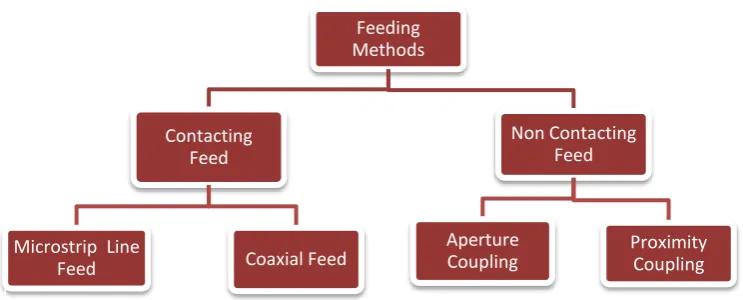
Feeding Methods
Contacting Feed
Microstrip Line
Feed Coaxial Feed
Non Contacting Feed
Aperture
ISSN(Online): 2320-9801 ISSN (Print): 2320-9798
I
nternational
J
ournal of
I
nnovative
R
esearch in
C
omputer
and
C
ommunication
E
ngineering
(A High Impact Factor, Monthly, Peer Reviewed Journal) Website: www.ijircce.com
Vol. 7, Issue 11, November 2019
10. Y. P. Selvam et al., "A Low-Profile Frequency- and Pattern-Reconfigurable Antenna," in IEEE Antennas and Wireless Propagation Letters, vol. 16, pp. 3047-3050, 2017.
11. C. Kumar, M. I. Pasha and D. Guha, "Defected Ground Structure Integrated Microstrip Array Antenna for Improved Radiation Properties," in IEEE Antennas and Wireless Propagation Letters, vol. 16, pp. 310-312, 2017.