Secure IOT Plotform For Industrial Control Systems
Telugu Ravi Kumar1, M.Anil Kumar2, S.Mahoob Basha3
1
P.G. Scholar, 2Assistant Professor, 3Head of the Department
1,2,3Branch:Electronics And Communication Engineering (Embedded Systems) 1,2,3
Geethanjali College Of Engineering And Technology, Nannur[V], Kurnool. Email Id : [email protected], [email protected]
Abstract
Supervisory control and data acquisition (SCADA) systems, are part of industrial control system (ICS), have been playing crucial roles in real-time industrial automation and controls. Through the evolution of 3rd generation, or networks
based system, SCADA systems are
connected to almost types of networks such as wired, wireless, and cellular and satellite communication, but security is still a big challenge for SCADA system while communicating within. Internet of things (IoT) is a ubiquitous platform, a new advance enhancement, for efficient SCADA system, where billions of network devices, with smart sensing capabilities, are
networked over the Internet access.
Deployment of smart IoT platform, SCADA system will significantly increase system efficiency, scalability, and reduce cost. Security is still a major issue for both-, as they were initially designed without any priority and requirements of security.
This study modeled IoT-SCADA system and deployed a security mechanism, employing of cryptography based algorithm, which provided a secure transmission channel while each time communication occurred, between the field devices in the
SCADA system. Proposed security
implementation, and computed
measurements analyzed as potential security building block against authentication and confidentiality attacks.
Keywords:- SCADA, ICS, IOT, Microprocessor, ATmega
INTRODUCTION
With the recent developments in
technology, all processes are being
automated. Apart from industrial
automation, automation is prevalent in the domestic domain making homes more smart and secure. It has also helped reduce human
effort enabling the control of
devices/appliances with great ease while being energy efficient. Various home automation models have been implemented incorporating Android platforms, Global System for Mobile communications (GSM) modules, Wi-Fi-based systems etc., into the fundamental microprocessor, sensor and actuator network. The wide application of
microprocessors is not confined to
domestic/home automation applications but can also be further extended into the industrial environment.
In the industrial domain, a fundamental automation system model is a basic control system, which includes an input/sensor, a controller and an output/actuator. This model can help implement any industrial application with appropriate hardware and
software selection. The application
discussed in this paper is level and temperature control during a continuous sequential switching operation.
A repetitive sequential switching
batch of screws in a factory. The sequence of the process flow for the mentioned activity would be cutting, heading, lathing, threading, heat treatment, electroplating, and packaging. This repetitive sequential nature of activities is widely observed in all industries and can be easily replicated on a small scale for small factories.
Level determination and monitoring systems are used in wastewater treatment plants, oil and gas industries, chemical and food processing industries, etc., for several applications including liquid storage, monitoring and control. These systems use
sensors based on different working
principles namely magnetic, ultrasonic, and Radiofrequency technology. The controllers used are mostly PLC’s or conventional Proportional-Integral (PI)/Proportional-Integral-Derivative (PID) controllers, which communicate between the sensor and the output device (usually a pump) to assist the inflow or outflow of fluid as required.
Temperature control and monitoring systems find its application in a wide range of process control industries. The input is derived from contact temperature sensors
like thermistors, thermocouples or
resistance temperature detectors or non-contact sensors based on infrared or similar technologies. These devices provide the required input to the system and trigger output as determined by the controller. Depending on the entire system either conventional controllers like the PI/PID controller or an ON/OFF controller is used. The latter is used if the temperature is not a very critical parameter in the system.
Microprocessors like the ATmega 328P (present on the Arduino), can make a number of logical control decisions by mere programming in C/C++ languages. Arduino UNO is compatible with a number of
software’s like Matrix Laboratory
(MATLAB), Parallax Data Acquisition (PLX-DAQ) tool apart from its main software, which is the Arduino IDE. The applications of this board can be extended even further by using compatible shields and external modules like GSM, Bluetooth, etc. With its affordable price, it thus, becomes a feasible option for a wide range of applications like Access Control, Data Logging and Automation.
LITERATURE SURVEY
Industrial automation using CAN protocol describe project is implemented to control the industrial loads that are run by DC motor based on the temperature variations of the process. Various process control systems are depends on the temperature. So this project achieves this with the use of CAN protocol which is highly efficient and reliable low-cost communication. Two microcontrollers are used in this project, one for acquiring temperature data and the other for controlling the DC motor. CAN Controller MCP2515 and CAN transceiver MCP2551 are connected to both microcontrollers to
implement CAN communication for
exchanging the data but disadvantage practically it is limited to 110 nodes due to the hardware transceivers. It supports cabling up to 250 meters.
Industrial automation using ZigBee describe the transmitter section, the Zigbee module is configured in such a way that it receives the data collected from the microcontroller and sends it to the remote receiver. In this system, the microcontroller is programmed to collect the data from an analog to digital
converter that continuously monitors
temperature, voltage and current
embedded circuitry wherein the microcontroller program compares all these data parameters with predefined set limits. If any parameter exceeds its limit, then the microcontroller sends command signals to a relay driver IC, which is responsible to operate different loads such as motors, relays, circuit breakers, etc. All these parameters’ information is also displayed on LCD display as a Human machine interface. In this way, industrial parameters can be easily monitored and controlled through the short range low cost and low powered
Zigbee communication technology. It
supports two ways communication between transmitting devices and controllers at 10-100 meters distance.
The LM35’s low output impedance, linear output, and precise inherent calibration make interfacing to readout or control circuitry especially easy. It can be used with single power supplies, or with plus and minus supplies. As it draws only 60 μA from its supply, it has very low self-heating, less than 0.1°C in still air.
The MQ-2 is a flammable gas and smoke sensor detects the concentrations of combustible gas in the air and outputs its reading as an analog voltage. The sensor can measure concentrations of flammable gas of 300 to 10,000 ppm. The MQ-2 gas sensor is sensitive to LPG, i-butane, propane, methane, alcohol, Hydrogen and smoke. They are used in gas leakage detecting equipments in family and industry and in portable gas detector.
Humidity Sensor is one of the most important devices that has been widely in consumer, industrial, biomedical, and
environmental etc. applications for
measuring and monitoring
Humidity.Humidity is defined as the amount of water present in the surrounding air. This water content in the air is a key
factor in the wellness of mankind. For example, we will feel comfortable even if the temperature is 00C with less humidity i.e. the air is dry.
Humidity is also a major factor for
operating sensitive equipment like
electronics, industrial equipment,
electrostatic sensitive devices and high voltage devices etc.
HR201 is a new kind of humidity-sensitive resistor made from organic macro molecule materials, it can be used in occasions like: hospitals, storage, workshop, textile industry, tobaccos, pharmaceutical field, meteorology, etc.
LCD stands for Liquid Crystal Display. LCD is finding wide spread use replacing LEDs (seven segment LEDs or other multi segment LEDs) because of the following reasons:
1. The declining prices of LCDs.
2. The ability to display numbers, characters and graphics. This is in contrast to LEDs, which are limited to numbers and a few characters.
3. Incorporation of a refreshing controller into the LCD, thereby relieving the CPU of the task of refreshing the LCD. In contrast, the LED must be refreshed by the CPU to keep displaying the data. The piezo buzzer produces sound based on
reverse of the piezoelectric effect. The generation of pressure variation or strain by the application of electric potential across a piezoelectric material is the underlying principle. These buzzers can be used alert a user of an event corresponding to a switching action, counter signal or sensor input. They are also used in alarm circuits.
INTRODUCTION TO EMBEDDED
SYSTEMS
Nearly 99 per cent of the processors manufactured end up in embedded systems. The embedded system market is one of the highest growth areas as these systems are used in very market segment- consumer electronics, office automation, industrial
automation, biomedical engineering,
wireless communication, data
communication, telecommunications,
transportation, military and so on.
Consumer appliances At home we use a number of embedded systems which include digital camera, digital diary, DVD player, electronic toys, microwave oven, remote controls for TV and air-conditioner, VCO
player, video game consoles, video
recorders etc. Today’s high-tech car has
about 20 embedded systems for
transmission control, engine spark control, air-conditioning, navigation etc. Even wristwatches are now becoming embedded systems. The palmtops are powerful embedded systems using which we can carry out many general-purpose tasks such as playing games and word processing.
Office automation: The office automation products using em embedded systems are copying machine, fax machine, modem, printer, scanner etc.
Industrial automation: Today a lot of industries use embedded systems for
process control. These include
pharmaceutical, cement, sugar, oil
exploration, nuclear energy, electricity generation and transmission. The embedded systems for industrial use are designed to carry out specific tasks such as monitoring
the temperature, pressure, humidity,
voltage, current etc., and then take appropriate action based on the monitored levels to control other devices or to send information to a centralized monitoring
station. In hazardous industrial
environment, where human presence has to
be avoided, robots are used, which are programmed to do specific jobs. The robots are now becoming very powerful and carry out many interesting and complicated tasks such as hardware assembly.
Medical electronics: Almost every
medical equipment in the hospital is an
embedded system. These equipments
include diagnostic aids such as ECG, EEG, blood pressure measuring devices, X-ray scanners; equipment used in blood analysis, radiation, colonoscopy, endoscopy etc. Developments in medical electronics have paved way for more accurate diagnosis of diseases.
Computer networking: Computer
networking products such as bridges,
routers, Integrated Services Digital
Networks (ISDN), Asynchronous Transfer Mode (ATM), X.25 and frame relay switches are embedded systems which
implement the necessary data
communication protocols. For example, a router interconnects two networks. The two networks may be running different protocol stacks. The router’s function is to obtain the data packets from incoming pores, analyze the packets and send them towards the destination after doing necessary protocol conversion. Most networking equipments, other than the end systems (desktop computers) we use to access the networks, are embedded systems
embedded systems that provide very low-cost voice communication over the Internet.
Wireless technologies: Advances in mobile communications are paving way for
many interesting applications using
embedded systems. The mobile phone is one of the marvels of the last decade of the 20th century. It is a very powerful embedded system that provides voice communication while we are on the move. The Personal Digital Assistants and the palmtops can now be used to access multimedia services over the Internet. Mobile communication infrastructure such as base station controllers, mobile switching centers are also powerful embedded
systems. Insemination: Testing and
measurement are the fundamental
requirements in all scientific and
engineering activities. The measuring equipment we use in laboratories to measure parameters such as weight, temperature, pressure, humidity, voltage, current etc. are all embedded systems. Test equipment such as oscilloscope, spectrum analyzer, logic
analyzer, protocol analyzer, radio
communication test set etc. are embedded systems built around powerful processors. Thank to miniaturization, the test and measuring equipment are now becoming portable facilitating easy testing and measurement in the field by field-personnel.
Security: Security of persons and
information has always been a major issue. We need to protect our homes and offices; and also the information we transmit and store. Developing embedded systems for security applications is one of the most lucrative businesses nowadays. Security devices at homes, offices, airports etc. for
authentication and verification are
embedded systems. Encryption devices are nearly 99 per cent of the processors that are manufactured end up in~ embedded
systems. Embedded systems find
applications in every industrial
segment-consumer electronics, transportation,
avionics, biomedical engineering,
manufacturing, process control and
industrial automation, data communication, telecommunication, defense, security etc. These are used to encrypt the data/voice being transmitted on communication links such as telephone lines. Biometric systems using fingerprint and face recognition are now being extensively used for user authentication in banking applications as well as for access control in high security buildings. Finance: Financial dealing through cash and cheques are now slowly paving way for transactions using smart cards and ATM (Automatic Teller Machine, also expanded as Any Time Money) machines. Smart card, of the size of a credit card, has a small micro-controller and memory; and it interacts with the smart card reader! ATM machine and acts as an electronic wallet. Well, the list goes on.
EXISTING SYSTEM
Industrial control system controls the devices whenever any of the sensed parameters exceed their respective set points. Controlling was automated but
monitoring of the parameters was
Fig: 4.1 Block Diagram Of Existing system
PROPOSED SYSTEM
This IOT based industrial control system allows the user to monitor the parameters from anywhere in the world. The sensors values will be updated on the web page continuously and the user can view these values on the web page. And also, not only a single industry plant values, but several plants can be put together and collectively the sensor data values can be viewed online.
Fig;5.1 Block Diagram Of Proposed system
5.2 ARDUINO UNO
Arduino is used for building different types of electronic circuits easily using of both a physical programmable circuit board usually microcontroller and piece of code running on computer with USB connection between the computer and Arduino. Programming language used in Arduino is just a simplified version of C++ that can easily replace thousands of wires with
words.
Fig :5.2 ARDUINO UNO
5.2.1 ARDUINO UNO-R3 PHYSICAL COMPONENTS
ATMEGA328P-PU microcontroller The most important element in Arduino Uno R3 is ATMEGA328P-PU is an 8-bit Microcontroller with flash memory reach to 32k bytes.
Features
1. High Performance, Low Power
Atmel®AVR® 8-Bit Microcontroller Family
– Most Single Clock Cycle Execution – 32 x 8 General Purpose Working
Registers
– Fully Static Operation
– Up to 20 MIPS Throughput at 20MHz – On-chip 2-cycle Multiplier
• High Endurance Non-volatile Memory Segments
– 32KBytes of In-System
Self-Programmable Flash program 2. Memory
– 1KBytes EEPROM – 2KBytes Internal SRAM
– Write/Erase Cycles: 10,000
Flash/100,000 EEPROM
– Data Retention: 20 years at 85°C/100 years at 25°C(1)
– Optional Boot Code Section with Independent Lock Bits
• In-System Programming by On-chip Boot Program
• True Read-While-Write Operation – Programming Lock for Software Security • Atmel® QTouch® Library Support – Capacitive Touch Buttons, Sliders and
Wheels
– QTouch and QMatrix® Acquisition – Up to 64 sense channels
3.
Atmel-42735B- ATmega328/P_Datasheet_Complete-11/2016
• Peripheral Features
– Two 8-bit Timer/Counters with Separate Prescaler and Compare Mode
– One 16-bit Timer/Counter with Separate Prescaler, Compare Mode, and Capture Mode
– Real Time Counter with Separate Oscillator
– Six PWM Channels
– 8-channel 10-bit ADC in TQFP and QFN/MLF package
• Temperature Measurement
– 6-channel 10-bit ADC in PDIP Package • Temperature Measurement
– Two Master/Slave SPI Serial Interface
– One Programmable Serial USART – One Byte-oriented 2-wire Serial Interface
(Philips I2C compatible)
– Programmable Watchdog Timer with Separate On-chip Oscillator
– One On-chip Analog Comparator – Interrupt and Wake-up on Pin Change • Special Microcontroller Features
– Power-on Reset and Programmable Brown-out Detection
– Internal Calibrated Oscillator
– External and Internal Interrupt Sources – Six Sleep Modes: Idle, ADC Noise
Reduction, Power-save, Power-down, Standby, and
4. Extended Standby • I/O and Packages
– 23 Programmable I/O Lines
– 28-pin PDIP, 32-lead TQFP, 28-pad QFN/MLF and 32-pad QFN/MLF
• Operating Voltage: – 1.8 - 5.5V
• Temperature Range: – -40°C to 105°C • Speed Grade:
– 0 - 4MHz @ 1.8 - 5.5V – 0 - 10MHz @ 2.7 - 5.5V – 0 - 20MHz @ 4.5 - 5.5V
• Power Consumption at 1MHz, 1.8V, 25°C
– Active Mode: 0.2mA
– Power-down Mode: 0.1μA
– Power-save Mode: 0.75μA (Including 32kHz RTC)
PRECESION CENTIGRADE
TEMPERATURE SENSOR
over a full −55 to +150°C temperature range.
The LM35’s low output impedance,
linear output, and precise inherent
calibration make interfacing to readout or control circuitry especially easy. It can be used with single power supplies, or with plus and minus supplies. As it draws only 60 μA from its supply, it has very low self -heating, less than 0.1°C in still air.
Features
1. Calibrated directly in ° Celsius (Centigrade)
2. Linear + 10.0 mV/°C scale factor
3. 0.5°C accuracy guaranteed (at
+25°C)
4. Rated for full −55° to +150°C range 5. Suitable for remote applications
6. Low cost due to wafer-level
trimming
7. Operates from 4 to 30 volts 8. Less than 60 μA current drain 9. Low self-heating, 0.08°C in still air 10. Nonlinearity only ±1⁄4°C typical Low impedance output, 0.1 W for 1 mA lo
Fig:5.3 LM 35 Circuit Diagrams The characteristic of this LM35 sensor is:
For each degree of centigrade
temperature it outputs 10milli volts.
In addition to thermistors, several other types of temperature sensors are used. The most common are Resistance Temperature Detectors (RTD) and integrated circuits (IC), such as the LM335 and AD590 types. Which sensor works best for a particular use is based on many factors. The table below gives a brief comparison of the benefits and drawbacks of each.
Table : 5.3 Different Types Temperatures
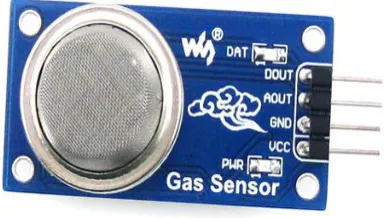
5.4 GAS SENSOR
The MQ-2 is a flammable gas and smoke sensor detects the concentrations of combustible gas in the air and outputs its reading as an analog voltage. The sensor can measure concentrations of flammable gas of 300 to 10,000 ppm. The MQ-2 gas sensor is sensitive to LPG, i-butane, propane, methane, alcohol, Hydrogen and smoke. They are used in gas leakage detecting equipments in family and industry and in portable gas detector.
Fig :5.4 Gas Sensor Specifications
● Supply Voltage:5V
● Sensitive to H2, LPG, CH4, CO, Alcohol, Smoke or Propane
● Analog and Digital Output
● Digital Out is High or Low based on a adjustable preset threshold.
1.1.1. Features:
● Operating Voltage is +5V
● Can be used to Measure or detect LPG, Alcohol, Propane, Hydrogen, CO and even methane
● Analog output voltage: 0V to 5V
● Digital Output Voltage: 0V or 5V (TTL
Logic)
● Preheat duration 20 seconds
● Can be used as a Digital or analog sensor
● The Sensitivity of Digital pin can be varied using the potentiometer
Selecting between Sensor type and module type:
When it comes to measuring or detecting a
particular Gas the MQ series Gas
sensors are the most commonly used ones. These sensors can either be purchased as a module or as just the sensor alone. If you are trying to only detect (not measuring ppm) the presence of a gas then you can buy it as a module since it comes with an op-amp comparator and a digital out pin.
Where to use MQ-2 Gas sensor:
The MQ-2 Gas sensor can detect or measure gasses like LPG, Alcohol, Propane, Hydrogen, CO and even methane. The module version of this sensor comes with a Digital Pin which makes this sensor to operate even without a microcontroller and that comes in handy when you are only trying to detect one particular gas. When it
comes to measuring the gas in ppm the analog pin has to be used, the analog pin also TTL driven and works on 5V and hence can be used with most common microcontrollers.
So if you are looking for a sensor to detect or measure gasses like LPG, Alcohol, Propane, Hydrogen, CO and even methane with or without a microcontroller then this sensor might be the right choice for you.
How to use MQ-2 Sensors to detect gas: Using an MQ sensor it detects a gas is very easy. You can either use the digital pin or the analog pin to accomplish this. Simply power the module with 5V and you should notice the power LED on the module to glow and when no gas it detected, the output LED will remain turned off meaning the digital output pin will be 0V. Remember that these sensors have to be kept on for pre-heating time (mentioned in features above) before you can actually work with it. Now, introduce the sensor to the gas you want to detect and you should see the output LED to go high along with the digital pin, if not use the potentiometer until the output gets high. Now every time your sensor gets introduced to this gas at this particular concentration the digital pin will go high (5V) else will remain low (0V).
You can also use the analog pin to achieve the same thing. Read the analog values (0-5V) using a microcontroller, this value will be directly proportional to the concentration of the gas to which the sensor detects. You can experiment with this values and check
how the sensor reacts to different
concentration of gas and develop your program accordingly.
How to use the MQ-2 sensor to measure PPM
also help you to distinguish one gas from another. So to measure PPM you can directly use a module. A basic wiring for the sensor from datasheet is shown below.
1.1.2. Fig:5.4.1 Gas Sensor wiring Diagram
Applications
● Detects or measure Gases like LPG, Alcohol, Propane, Hydrogen, CO and even methane.
● Air quality monitor. ● Gas leak alarm.
● Safety standard maintenance.
● Maintaining environment
standards in hospitals.
HUMIDITY SENSOR
Humidity Sensor is one of the most important devices that has been widely in consumer, industrial, biomedical, and
environmental etc. applications for
measuring and monitoring Humidity.
Humidity is defined as the amount of water present in the surrounding air. This water content in the air is a key factor in the wellness of mankind. For example, we will feel comfortable even if the temperature is 00C with less humidity i.e. the air is dry.
Humidity is also a major factor for
operating sensitive equipment like
electronics, industrial equipment,
electrostatic sensitive devices and high
voltage devices etc. Such sensitive
equipment must be operated in a humidity environment that is suitable for the device. Hence, sensing, measuring, monitoring and controlling humidity is a very important task.
Some of the important areas of application for sensing, measuring and controlling Humidity are mentioned below.
Domestic: Sensing and controlling humidity in our homes and offices is important as higher humidity conditions will affect the blood flow. Other areas include cooking, indoor plantation etc.
Industrial: In industries like refineries, chemical, metal, or other industries where furnaces are used, high humidity will reduce the amount of oxygen in the air and hence reduces the firing rate. Other industries like food processing, textile, paper etc. also need control of humidity.
Agriculture: Irrigation techniques like drip irrigation need accurate moisture content for plants. Also, the moisture in the soil plays an important role in the proper growth of the plant. Other areas where humidity control is required is indoor vegetation. Electronics and Semiconductor: Almost all electronic devices are rated with a range of humidity values in which they work as expected. Generally, this value will be something like 10% – 50% Humidity. Semiconductor Fabs (Fabrication Plants) should maintain very precise temperature and humidity values as even minute difference can show a huge impact in the production.
Medical: Medical equipment like ventilators, incubators, sterilizers etc. need humidity control. It is also used in
pharmaceutical plants and biological
processes.
1.1.1. Important Terms Related to Humidity
Moisture refers to the water content in solids and liquids. The term Humidity refers to the water content in gases (air).
Absolute Humidity: Absolute Humidity (AH) is the ratio of mass of the water vapour to the volume of the air. If m is the mass of the water vapour and V is the total volume i.e. volume of air and water vapour mixture, then Absolute Humidity AH is given by
AH = m/V
Absolute Humidity doesn’t take temperature in to account but it changes with temperature and pressure.
Relative Humidity: Whenever we talk about measuring Humidity, it usually Relative Humidity that we are talking about (unless otherwise specified). Relative Humidity or RH is the ratio of the actual water vapour pressure present in the air at a temperature to the maximum water vapour pressure present in the air at the same temperature.
In weather reports and forecasts, the probability of precipitation or dew or fog is indicated using Relative Humidity and hence, it is considered an important metric.
Relative Humidity takes both temperature and pressure in to consideration. Hence, the Humidity Sensors which measure Relative Humidity, measure both the moisture content as well as the air temperature. NOTE: For temperatures above 1000C, measuring Relative Humidity (RH) is of no use as it would deliver misleading values.
Specific Humidity: Specific Humidity (SH) is the ratio of mass of the water vapor to the total mass of the air.
Mixing Ratio or Humidity Ratio: Mixing Ratio is the ratio of mass of the water vapor to mass of the dry air
Dew Point Temperature: Dew Point Temperature is the temperature at with the water vapor content is saturated in the air. At Dew Point temperature, the Relative Humidity RH is 100%. In other words, for the air to hold maximum amount of water vapor (or moisture), it has to reach Dew Point Temperature.
Humidity Sensors – Classification and Working Principles
Humidity Sensors are very important devices that help in measuring the environmental humidity. Technically, the device used to measure the humidity of the atmosphere is called Hygrometer. Humidity Sensors or Hygrometers can be classified based on the type of humidity it is used for measuring i.e.
Absolute Humidity (AH) sensors or Relative Humidity (RH) sensors: Humidity Sensors can also be classified based on the parameter used for measuring Humidity i.e. Capacitive Humidity Sensors, Electrical
Conductivity (or Resistive) Humidity
Sensors and Thermal Conductivity
Humidity Sensors.
Resistive Humidity sensor-HR201
occasions like: hospitals, storage, workshop, textile industry, tobaccos, pharmaceutical field, meteorology, etc.
Features
● Excellent linearity
● Low power consumption
● Wide measurement range
● Quick response
● Anti-pollution ● High stability
● High performance-price ratio
Technical Specifications:
● Operating range: humidity
(20-95%RH), temperature(0-60Celsius)
● Power supply: 1.5V AC(Max sine)
● Operating frequency: 500Hz-2kHz
● Rated power: 0.2mW(Max sine)
● Central value: 23kΩ(at 25Celsius, 1kHz ,1V AC, 60%RH)
● Impedance range: 19.8-50.2kΩ(at
25Celsius, 1kHz ,1V AC, 60%RH)
● Accuracy: +-5%RH
● Hysteresis: +-1%RH
● Long-term stability: +-1%RH/year
● Response time: <10s
● Dimensions: with case 12*15*5mm, without case 8*10*0.7mm
5.6 LIQUID CRYSTAL DISPLAY
LCD stands for Liquid Crystal Display. LCD is finding wide spread use replacing LEDs (seven segment LEDs or other multi segment LEDs) because of the following reasons:
1. The declining prices of LCDs. 2. The ability to display numbers, characters and graphics. This is in contrast to LEDs, which are limited to numbers and a few characters.
3. Incorporation of a refreshing controller into the LCD, thereby relieving the CPU of the task of refreshing the LCD.
In contrast, the LED must be refreshed by the CPU to keep displaying the data.
4. Ease of programming for
characters and graphics.
These components are “specialized” for being used with the microcontrollers, which means that they cannot be activated by standard IC circuits. They are used for writing different messages on a miniature LCD.
HARDWARE IMPLEMENTATION OF THE PROJECT
This chapter briefly explains about the Hardware Implementation of the project. It discusses the design and working of the design with the help of block diagram and circuit diagram and explanation of circuit diagram in detail. It explains the features, timer programming, serial communication, interrupts of atmega328 microcontroller. It also explains the various modules used in this project.
Project Design
The implementation of the project design can be divided in two parts.
− Hardware implementation
− Firmware implementation
Hardware implementation deals in drawing the schematic on the plane paper according to the application, testing the schematic design over the breadboard using the various IC’s to find if the design meets the objective, carrying out the PCB layout of the schematic tested on breadboard, finally preparing the board and testing the designed hardware.
INTRODUCTION TO MICROCONTROLLER
Based on the Processor side Embedded Systems is mainly divided into 3 types 1. Microprocessor: - are for general purpose eg: our personal computer
2. Microcontroller: - are for specific applications, because of cheaper cost we will go for these
3. DSP (Digital Signal Processor ):- are for high and sensitive application purpose
MICROCONTROLLER VERSUS
MICROPROCESSOR
A system designer using a general-purpose microprocessor such as the Pentium or the 68040 must add RAM, ROM, I/O ports, and timers externally to make them functional. Although the addition of external RAM, ROM, and I/O ports makes these systems bulkier and much more expensive, they have the advantage of versatility such that the designer can decide on the amount of RAM, ROM and I/O ports needed to fit the task at hand.
A Microcontroller has a CPU (a
microprocessor) in addition to a fixed amount of RAM, ROM, I/O ports, and a timer all on a single chip. In other words, the processor, the RAM, ROM, I/O ports and the timer are all embedded together on one chip; therefore, the designer cannot add any external memory, I/O ports, or timer to it. The fixed amount of on-chip ROM, RAM, and number of I/O ports in Microcontrollers makes them ideal for many applications in which cost and space are critical.
Table: 6.1 microprocessor vs micro controller
OTHER ARDUINO UNO R3 PARTS Input and Output
Each of the 14 digital pins on the Uno can be used as an input or output, using pin Mode (), digital Write(), and digital Read() functions. They operate at 5 volts. Each pin can provide or receive a maximum of 40 mA and has an internal pull-up resistor (disconnected by default) of 20-50 k Ohms.
In addition, some pins have specialized functions:
● Serial: 0 (RX) and 1 (TX). Used to receive (RX) and transmit (TX) TTL serial data. These pins are connected to
the corresponding pins of the
ATmega8U2 USB-to-TTL Serial chip. ● External Interrupts: 2 and 3. These
pins can be configured to trigger an interrupt on a low value, a rising or falling edge, or a change in value. ● PWM: 3, 5, 6, 9, 10, and 11. Provide
8-bit PWM output with the analog Write() function.
● SPI: 10 (SS), 11 (MOSI), 12 (MISO), 13 (SCK). These pins support SPI communication using the SPI library. ● LED: 13. There is a built-in LED
function.
● Additionally, some pins have
specialized functionality:
● TWI: A4 or SDA pin and A5 or SCL pin. Support TWI communication using the Wire library. There are a couple of other pins on the board:
● AREF: Reference voltage for the analog inputs. Used with analog Reference().
● Reset: Bring this line LOW to reset the microcontroller. Typically used to add a reset button to shields which block the one on the board.
MEMORY
The ATmega328 has 32 KB (with 0.5 KB used for the boot loader). It also has 2 KB of SRAM and 1 KB of EEPROM (which can be read and written with the EEPROM library).
COMMUNICATION
The Arduino Uno has a number of facilities for communicating with a computer, another Arduino, or other microcontrollers. The ATmega328 provides UART TTL (5V) serial communication, which is available on digital pins 0 (RX) and 1 (TX). An ATmega16U2 on the board channels this serial communication over USB and appears as a virtual com port to software on the computer. The '16U2 firmware uses the standard USB COM drivers, and no external driver is needed. However, on Windows, a .inf file is required. The Arduino software includes a serial monitor which allows simple textual data to be sent to and from the Arduino board. The RX and TX LEDs on the board will flash when data is being transmitted via the USB-to-serial chip and USB connection to the computer (but not for serial communication on pins 0 and 1).
A Software Serial library allows for serial communication on any of the Uno's digital pins. The ATmega328 also supports I2C
(TWI) and SPI communication. The Arduino software includes a Wire library to simplify use of the I2C bus; see the
documentation for details. For SPI
communication, use the SPI library.
PROGRAMMING
The Arduino Uno can be programmed with the Arduino software (download). Select "Arduino Uno from the Tools > Board menu (according to the microcontroller on your board). For details, see the reference and tutorials.
The ATmega328 on the Arduino Uno comes preburned with a boot loader that allows you to upload new code to it without
the use of an external hardware
programmer. It communicates using the original STK500 protocol (reference, C header files).
You can also bypass the boot loader and program the microcontroller through the ICSP (In-Circuit Serial Programming) header; see these instructions for details.
The ATmega16U2 (or 8U2 in the rev1 and rev2 boards) firmware source code is available.
ATmega16 U2/8U2 is loaded with a DFU boot loader, which can be activated by: On Rev1 boards: connecting the solder jumper on the back of the board (near the map of Italy) and then resetting the 8U2.
On Rev2 or later boards: there is a resistor that pulling the 8U2/16U2 HWB line to ground, making it easier to put into DFU mode. You can then use Atmel's FLIP
software (Windows) or the DFU
programmer (Mac OS X and Linux) to load a new firmware. Or you can use the ISP header with an external programmer (overwriting the DFU boot loader).
The Atmel AVR® core combines a rich instruction set with 32 general purpose working registers. All the 32 registers are directly connected to the Arithmetic Logic Unit (ALU), allowing two independent registers to be accessed in a single instruction executed in one clock cycle. The resulting architecture is more code efficient while achieving throughputs up to ten times
faster than conventional CISC
microcontrollers.
Atmel offers the Q Touch® library for embedding capacitive touch buttons, sliders
and wheels functionality into AVR
microcontrollers. The patented charge-transfer signal acquisition offers robust sensing and includes fully debounced reporting of touch keys and includes Adjacent Key Suppression® (AKS™) technology for unambiguous detection of key events. The easy-to-use Q Touch Suite tool chain allows you to explore, develop and debug your own touch applications. The device is manufactured using Atmel’s
high density non-volatile memory
technology. The On-chip ISP Flash allows the program memory to be reprogrammed In-System through an SPI serial interface, by a conventional nonvolatile memory programmer, or by an On-chip Boot program running on the AVR core.
The Boot program can use any interface to download the application program in the Application Flash memory. Software in the Boot Flash section will continue to run while the Application Flash section is updated, providing true Read-While-Write operation. By combining an 8-bit RISC CPU with In-System Self-Programmable Flash on a monolithic chip, the Atmel ATmega328/P is a powerful microcontroller that provides a highly flexible and cost effective solution to many embedded control applications. The ATmega328/P is supported with a full suite of program and
system development tools including: C Compilers, Macro Assemblers, Program Debugger/Simulators, In-Circuit Emulators, and Evaluation kits.
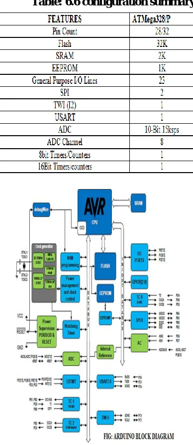
Table: 6.6 configuration summary
Fig 6.6: Arduino Block Diagram
Fig:6.6.1 Pin Diagram
PIN DESCRIPTIONS VCC - Digital supply voltage GND – Ground
Port B (PB[7:0])
XTAL1/XTAL2/TOSC1/TOSC2
Port B is an 8-bit bi-directional I/O port with internal pull-up resistors (selected for each bit). The Port B output buffers have symmetrical drive characteristics with both high sink and source capability. As inputs, Port B pins that are externally pulled low will source current if the pull-up resistors are activated. The Port B pins are tri-stated when a reset condition becomes active, even if the clock is not running. Depending on the clock selection fuse settings, PB6 can be used as input to the inverting Oscillator amplifier and input to the internal clock operating circuit Depending on the clock selection fuse settings, PB7 can be used as output from the inverting Oscillator amplifier. If the Internal Calibrated RC Oscillator is used as chip clock source, PB[7:6] is used as TOSC[2:1] input for the Asynchronous Timer/Counter2 if the AS2
bit in ASSR is set. Port C (PC[5:0])
Port C is a 7-bit bi-directional I/O port with internal pull-up resistors (selected for each bit). The PC[5:0] output buffers have symmetrical drive characteristics with both high sink and source capability. As inputs, Port C pins that are externally pulled low will source current if the pull-up resistors are activated. The Port C pins are tri-stated when a reset condition becomes active, even if the clock is not running.
PC6/RESET
If the RSTDISBL Fuse is programmed, PC6 is used as an I/O pin. Note that the electrical characteristics of PC6 differ from those of the other pins of Port C. If the RSTDISBL Fuse is un programmed, PC6 is used as a Reset input. A low level on this pin for longer than the minimum pulse length will generate a Reset, even if the clock is not running. Shorter pulses are not guaranteed to generate a Reset. The various special features of Port C are elaborated in the Alternate Functions of Port Csection.
Port D (PD[7:0])
Port D is an 8-bit bi-directional I/O port with internal pull-up resistors (selected for each bit). The Port D output buffers have symmetrical drive characteristics with both high sink and source capability. As inputs, Port D pins that are externally pulled low will source current if the pull-up resistors are activated. The Port D pins are tri-stated when a reset condition becomes active, even if the clock is not running.
AVCC
AREF
AREF is the analog reference pin for the A/D Converter.
ADC[7:6] (TQFP and VFQFN Package Only)
In the TQFP and VFQFN package, ADC[7:6] serve as analog inputs to the A/D converter. These pins are powered from the analog supply and serve as 10-bit ADC channels.
I/O Multiplexing
Each pin is by default controlled by the PORT as a general purpose I/O and alternatively it can be assigned to one of the peripheral functions. The following table describes the peripheral signals multiplexed to the PORT I/O pins.
TYPES OF ARDUINO BOARDS:-
❖ Arduino UNO.
❖ Arduino MEGA.
❖ Arduino MINI.
❖ Arduino NANO
❖ Arduino DUE.
❖ Arduino YUN.
❖ Arduino Lily pad.
❖ Arduino Duemilanova.
Apart from this there are many more boards that can be used. As it’s open source instead of Arduino you can also find, Freeduino, Arkduino etc. available in the market. Selection of Board should be done according to the application.
Choosing the right controller
The table below compares the Arduino Uno, Leonardo, and our A-Star 32U4 Prime controllers. The A-Star Primes are based on
the same ATmega32U4 AVR
microcontroller as the Leonardo and ship with Arduino-compatible boot loaders. The
Primes also offer many advantages,
including superior power management that enables efficient operation from 2.7 V to
11.8 V (LV version) or 5 V to 36 V (SV version).
Table 6.8 Types of Arduino
FIRMWARE IMPLEMENTATION OF THE PROJECT DESIGN
FIRMWARE IMPLEMENTATION This chapter briefly explains about the firmware implementation of the project. The required software tools are discussed in the following section.
Software Tool Required
Arduino 1.0.6 software tools used to program microcontroller. The working of software tool is explained below in detail. PROGRAMMING
MICROCONTROLLER
Arduino is a tool for making computers that can sense and control more of the physical world than your desktop computer. It's an open-source physical computing platform based on a simple microcontroller board, and a development environment for writing software for the board.
One of the difficulties of programming microcontrollers is the limited amount of resources the programmer has to deal with. In personal computers resources such as RAM and processing speed are basically
limitless when compared to
microcontrollers. In contrast, the code on microcontrollers should be as low on resources as possible
ABOUT ARDUINO COMPILER
GET AN ARDUINO BOARD AND USB CABLE
You also need a standard USB cable (A plug to B plug): the kind you would connect to a USB printer, for example. (For the Arduino Nano, you'll need an A to Mini-B
cable instead).
FIG : 7.3 ARDUINO AND USB CABLE CONNECT THE BOARD
The Arduino Uno, Mega, Duemilanove and Arduino Nano automatically draw power from either the USB connection to the computer or an external power supply. If you're using an Arduino Diecimila, you'll need to make sure that the board is configured to draw power from the USB connection. The power source is selected with a jumper, a small piece of plastic that fits onto two of the three pins between the USB and power jacks. Check that it's on the
two pins closest to the USB port. Connect the Arduino board to your computer using the USB cable. The green power LED (labeled PWR) should go on.
Fig :7.3.1 Arduino window Open the blink example
Open the LED blink example sketch: File > Examples > 1.Basics > Blink.
Fig:7.3.2 Opening Blink Example
Fig: 7.3.3 Source Code Written In ARDUINO
You'll need to select the entry in the Tools > Board menu that corresponds to your Arduino.
Fig: 7.34 Selecting An ARDUINO UNO 7.4 WRITING SKETCHES
Software written using Arduino are
called sketches. These sketches are written in the text editor. Sketches are saved with the file extension .ino. It has features for cutting/pasting and for searching/replacing text. The message area gives feedback while saving and exporting and also displays errors. The console displays text output by
the Arduino environment including
complete error messages and other
information. The bottom right hand corner of the window displays the current board and serial port. The toolbar buttons allow you to verify and upload programs, create, open and save sketches and open the serial monitor. NB: Versions of the IDE prior to 1.0 saved sketches with the extension .pde. It is possible to open these files with version 1.0, you will be prompted to save the sketch with the .ino extension on save.
Table:7.4 writing sketches
Additional commands are found within the five menus: File, Edit, Sketch, Tools, Help. The menus are context sensitive which means only those items relevant to the work currently being carried out are available.
SELECT YOUR SERIAL PORT
Select the serial device of the Arduino board from the Tools | Serial Port menu. This is
likely to be COM3 or higher
(COM1and COM2 are usually reserved for hardware serial ports). To find out, you can disconnect your Arduino board and re-open the menu; the entry that disappears should be the Arduino board. Reconnect the board and select that serial port.
UPLOAD THE PROGRAM
Before uploading your sketch, you need to select the correct items from the Tools > Board and Tools > Serial Port menus. The boards are described below. On the Mac, the serial port is probably something like /dev/tty.usbmodem241 On
Windows, it's
probably COM1 or COM2 (for a serial
board) or COM4, COM5, COM7, or higher (for a USB board) - to find out, you look for USB serial device in the ports section of the Windows Device Manager. On Linux, it
should be /dev/ttyUSB0,/dev/ttyUSB1 or
similar.
When you upload a sketch, you're using the Arduino boot loader, a small program that has been loaded on to the microcontroller on your board. It allows you to upload code without using any additional hardware. The boot loader is active for a few seconds when the board resets; then it starts whichever sketch was most recently uploaded to the microcontroller. The boot loader will blink the on-board (pin 13) LED when it starts (i.e. when the board resets).
Now, simply click the "Upload" button in the environment. Wait a few seconds - you should see the RX and TX leds on the board flashing. If the upload is successful, the message "Done uploading." will appear in the status bar. (Note: If you have an Arduino Mini, NG, or other board, you'll need to physically present the reset button on the board immediately before pressing the upload button.)
Fig:7.5 Compilation Under Process
A few seconds after the upload finishes, you should see the pin 13 (L) LED on the board start to blink (in orange). If it does, congratulations, You've gotten Arduino up-and-running.
RESULTS AND DISCUSSIONS WORKING PROCEDURE
Secured IOT platform for Industrial control system is a working model designed to monitor and control the industry parameters continuously. This model uses
Arduino as the main controlling element to implement the tasks efficiently.
The microcontroller unit consists of three sensors-gas sensor, humidity and temperature sensor. The data from sensors
are continuously processed by the
microcontroller and uploaded to the webpage and also the buzzer is activated immediately if gas sensor or humidity sensor values exceed their set points. If the temperature sensor triggers, then the fan will be switched on.
The system will remain in
deactivated mode initially. After the system activation, the system will work as follows.
The temperature sensor LM35 will
constantly send the room temperature values to ARDUINO. If temperature value is above a certain level, ARDUINO unit immediately switches on the fan. The gas sensor detects the emission of any gases in the industry and if it detects any gases, this value will be sensed by the ARDUINO and it triggers an alarm. The humidity sensor measures the humidity level and if this value changes, this value will be sensed by the ARDUINO and it triggers an alarm. LCD is used to display the introductory messages, Wi-Fi module establishes the communication between the ARDUINO and Internet and the sensor data will be continuously uploaded on the webpage.
FUTURE SCOPE
As a future enhancement to this working model, data can be analyzed in advance. For instance, the data is collected and has to be analyzed for a period of 1 year. This can be achieved using Artificial Intelligence. Integrating AI in this project, we can analyze and estimate the values for a certain period in advance.
APPLICATIONS
In Automation of Industries In Railways
Home Automation with sensors REFERENCE
Secured IoT platform for Industrial control system-references
[1] Andrea Zanella, Lorenzo Vangelista, “Internet of Things for Smart Cities” IEEE Internet of Things Journal, vol. 1, no. 1, February 2014.
[2] Minal Nikose, Pratibha Mishra, Avinash Agrawal, “ A Review on Industrial Automation by Zigbee Based Wireless
Remote Controller”, International
Journal of Scientific & Technology Research volume 3, issue 4, April 2014. [3] P.Ram Babu, C.Madhusudan, “Industrial
Automation and Control System Using Can Protocol”. International Journal & Magazine of Engineering, Technology, Management and Research, Volume No: 2 (2015), Issue No: 12 (December). [4] B. Meena Kumari1, M. Satya Sailaja,