THE SINGULARITY PROBLEM AT THE
WIRE/SURFACE JUNCTION REGION FOR ANTENNA AND ARRAYS WITH BODIES OF REVOLUTION
X. Cao and J. Gao
Telecommunication Engineering Institute Air Force Engineering University of CPLA Shaanxi 710077, P. R. China
Abstract—In this paper, a fast and efficient method based on MOM is proposed for the analysis of antenna and array mounted on bodies of revolution. An attachment mode is introduced to ensure the continuity of current density at the junction region between wire antenna and cylindrical surface. A method based on suitable changes of coordinates and domains is presented to extract singular point of the self-impedance element calculation at junction region and accurate impedance can be obtained. Taking the antennas and array mounted on a finite solid conducting cylinder as an example, the impedance characteristics and radiation pattern are calculated. The good agreement between the results obtained by using the analysis method presented in this paper and those of CST and NEC software reveals the accuracy and high efficiency of this method.
1. INTRODUCTION
of the cylinder are expanded as overlapping triangular functions and complex Fourier mode. It is an efficient procedure to reduce the order of matrix in MOM and the computing time and storage required [3–6]. But the efficiency and accuracy of computation results are hindered because of the singularity that appears in impedance matrix elements. When it comes to the singularity problem of the impedance matrix elements for the revolution body and wire antenna in MOM, there are a lot of literature report [1–9], but there is little information considering the singularity of the computation of self-impedance at the junction region between wire antenna and cylinder surface. In this paper, a rigorous method is firstly introduced to extract the singularity of the Greens function appearing within the integrands of the self-impedance element at the junction region between wire antenna and cylindrical surface, and the effect of the size of the junction region on the cylinder surface on the self-impedance of the attachment point is analysed. The input impedance and radiation pattern of wire antenna and patch array of an L-probe feed mounted on the finite solid cylinder obtained by the method in this paper agree well with the CST and NEC results. 2. THEORY
The geometry model of wire antenna with revolution body as shown in Fig. 1, in terms of the enforcing the boundary condition Ei(r)
tan
+
υ
uρ ^t u u^z
ϕ
y
x
z
o ^
E
s
r
tan = 0 , so
Eir
tan
= −Esr
tan=jωµ
S J r G R ds − 1 jωε∇ s S
∇ ·J
r G
R
ds (1)
In whichR=r−ris the vector distance between the source point
r to the observation pointr,R=R=
r2+r2−2rrcos(ϕ−ϕ),
and G(R) =e−jkR/4πR is the free-space Green’s function. J
r
is the surface current density on the conducting.
J r
=Js
r
+Jw
r
+JA
r
(2)
In which Js
r
, Jw
r
, and JA
r
represent the current density on the cylinder surface, wire antenna and junction region between wire and cylinder surface, respectively.
Considering the rotational symmetry geometry characteristic of the revolution body, the equivalent current is a vector quantity and can be expressed as a superposition of two orthogonal vectors at any points on the surface. The obvious choice for the current vectors is surface tangential vector ˆut, which is rotationally symmetric about the
angle ϕ, and the azimuthal vector ˆuϕ. Therefore the surface current
density of the revolution body can be expressed as follows
J =Jtuˆt+Jϕuˆϕ = M
i=1 N
n=−N
InistJ
st
ni+I
sφ ni J sφ ni
(A/m2) (3)
J t
ni= ˆuti
T(t−ti)
ρ e
jnφ
Jφni= ˆuϕi
T(t−ti)
ρ e
jnφ
(4)
where ˆuti and ˆuϕi are the unit vectors along t and ϕ direction, and
ρ is the radius of the revolution body, T(t−ti) is the triangle base
For wire antenna, suppose the currents distribution Jw on wire
antenna is expanded with piecewise triangular basis functions.
Jw =
N w
l=1
ˆ
uwl IlwTl(h) (A/m) (5)
where, ˆuwl is the unit vector of the lth segment along wire antenna, Tl(h) represents a triangular function, and Ilw is the unknown wire
current coefficient of the corresponding segment.
A special attachment mode is introduced wherever wire antenna is connected with the cylinder surface, as shown in Fig. 2, in order to ensure continuity of current flowing from wire antenna to cylinder surface. Then, no discontinuity occurs at any conductive joint part. For a point r in the junction region, the basis function of which is defined as follows
JAr=IA
Jal r∈Sa
Jad r∈Sd
(6)
where,Jal =ul Ta
l(h)
2π a is the current density on the wire segment nearest
the junction region.
J
a
d = −
ur2π r1
b−r b−a
is the current density over the cylindrical surface near the junction regions a, and b are the inner and outer radii of the annulus in the junction region, respectively.
Substitute Eq. (3), Eq. (5), and Eq. (6) into Eq. (1). The surface current to each region can be obtained by solving Eq. (1) using Galerkin procedure.
3. IMPEDANCE EXPRESSIONS AND THE
EXTRACTING THE SINGULARITY POINT IN THE INTEGRAL
Using Galerkin’s method to solve Eq. (1), The general matrix equation can be obtained, with the following form
[Zss] [Zsw] ZsA [Zws] [Zww] ZwA
ZAs ZAw ZAA
·
[Is]
[Iw]
IA
=
[Vs]
[Vw]
VA
(7)
parts of the revolution body. Similarly, the revolution body-wire, the revolution body-junction, the wire-wire, the wire-junction and junction-junction impedance matrices are denoted by [Zsw], ZsA, [Zww], ZwA, and ZAA, respectively. [Vs], [Vw], and VA are the excitation voltage matrix of on the cylinder, the wire, and the junction region, respectively. [Is], [Iw], and IA are corresponding surface current to be determined.
The computation of the self impedance matrix and the mutual impedance matrix for the revolution body and wire antenna have been introduced [5–9], the details of this evaluation will not be explained here for brevity. No information on junction region impedance element ZAA is available, here, the impedance of the wire/cylinder surface junction region are carefully treated in a special method.
For the wire/surface junction region self-impedance elementZAA, as shown in Fig. 2, it consists of a small disk basisJ
a
d on the cylinder
surface and a half triangle basis Jal on the wire. Using Galerkin’s method, the self-impedance element at the wire/surface junction region is described as follows
ZAA =
Wal, La
Jal
+
Wad, La
Jad
+
Wad, La
Jal
+
Wal, La
Jad
= jkη 4π h0 0 dh h0 0 dh Ta
h·Ta(h)·
ua·ua
−Ta(h)·Ta(h)
k2
e−jkR
R +
jkη 16π3(b−a)2
π −π dϕ b a dr π −π dϕ b a dr
b−r·(b−r)·
ur·ur
− 1
k2
e−jkR R
+ jkη 8π2(b−a)
h0 0 dh b a dr π −π dϕ
Ta(h)·(r−b)·
ua·
ur
− Ta(h)
k2
e−jkR
R
+ jkη 8π2(b−a)
Ta(h)·(r−b)·
ua·
ur
−Ta(h)
k2
e−jkR
R (8)
3.1. Extracting the Singularity Term in Integral
It can be seen the self-impedance ZAA of the junction region is composed of four terms, the self-impedance between wire antennas, the mutual-impedance between the wire and disk, and the self-impedance between disks. The second term in Eq. (8) is the self-impedance element between disks, which is expressed as ZAA
pp . There is a
singularity inZAA
pp whenr →r.
ZP PAA = jkη 16π3(b−a)2
π
−π
dϕ
b
a
dr
π
−π
dϕ
b
a
dr
b−r·(b−r)·
ur·ur
− 1
k2
e−jkR
R (9)
where, R=
r2+r2−2rrcos(ϕ−ϕ),
ur·ur= cos(ϕ−ϕ).
Let
ϕ−ϕ=α
ϕ+ϕ=β , according to the integral domain of Eq. (9), convert the integral domain ϕand ϕ toα and β, and suppose
Zr, r =
π
−π
dϕ
π
−π
dϕb−r·(b−r)·cos(ϕ−ϕ)− 1 k2
e−jkR
R
= 1 2
α
dα
β
dβf(α)
= 1 2
0
−2π
f(α)dα
2π+α
−2π−α
dβ+1 2
2π
0
f(α)dα
2π−α
−2π+α
dβ
= 8π·
π
0
f(α)dα−2
2π
0
f(α)αdα (10)
where
f(α) =b−r·(b−r)·cosα− 1 k2
e−jkR
Supposeα= 2π−ς, cosα= cosς, it can be obtained 2π 0 f(α)αdα= 2π 0
f(ς)(2π−ς)dς = 2π
2π
0
f(ς)dς−
2π
0
f(ς)ςdς (12)
So
2π
0
f(α)αdα=π
2π
0
f(α)dα= 2π
π
0
f(α)dα (13)
Substituted Eq. (13) into Eq. (10)
Zr, r= 4π
π
0
f(α)dα (14)
So the self-impedance term between disks.
ZP PAA = jkη 4π(b−a)2
b a dr b a
drZr, r
= jkη 4π(b−a)2
b a dr b a
drb−r·(b−r)·g− 1 k2h
(15)
where
g = 1 π
π
0
e−jkR
R cosαdα (16a)
h = 1 π
π
0
e−jkR
R dα (16b)
using Hanker Function, Eq. (16) can be written as
g= e
−jkR0
R0 1 π π 0
cosαdα+
∞
m=1
(r·r)m
m
l=0
(m+l)! m!·l!·(m−l)! ·2
−l(jk)m−l
R−0(m+l)
!
·
π
0
cosmα·cosαdα
h= e
−jkR0
R0 1 + ∞ m=1
(r·r)m
m
l=0
(m+l)! m!·l!·(m−l)!·2
−l(jk)m−lR−(m+l) 0
!
·
π
0
cosmαdα
(17b)
where, R0 = %
r2+r2 and (r, r)∈[a, b].
So the singularity in integral Eq. (8) can be extracted, and
ZAA = jkη 4π h0 0 dh h0 0 dh Ta
h·Ta(h)−
Ta(h)·Ta(h)
k2
h
+ jkη 4π(b−a)2
b a dr b a
dr&b−r·(b−r)·g− 1 k2 ·h
'
+ jkη 2π(b−a)
h0 o dh b a dr
−Ta(h)
k2
h (18)
3.2. Determination the Outer Radius b of the Annulus
The inner radiusa of the annulus corresponds to the wire radius, the outer radius b of an annulus is usually chosen to be between 0.1λ to 0.25λ, which has effect on the impedance characteristic, especially on the impedance value of the resonant frequency point. The admittance versusb is calculated in the resonant frequency, as shown in Fig. 3, it can be seen that the admittance converges when the outer radius bis greater than 0.1λ. So we choose b= 0.107λin the paper.
4. VALIDATION OF THE ARITHMETIC
Figure 2. Attachment region at the wire/surface.
0.00 0.04 0.08 0.12 0.16 0.20 0.24 0.28
-10 0 10 20 30 40
Admittance(m
Ω
−1 )
b/λ
Conductance Susceptance
0.107λ
Figure 3. Input admittance of the junction point versus disk radiusb.
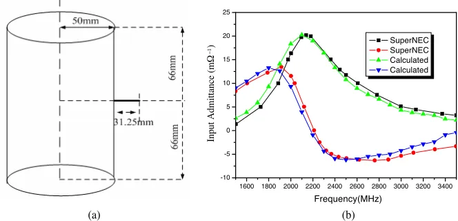
1600 1800 2000 2200 2400 2600 2800 3000 3200 3400 -10
-5 0 5 10 15 20 25
−1
Frequency(MHz)
SuperNEC SuperNEC Calculated Calculated
Input Admittance (m
Ω
)
(a) (b)
Figure 4. (a) The dipole vertical the axis of the cylinder. (b) The input admittance vary as the frequency.
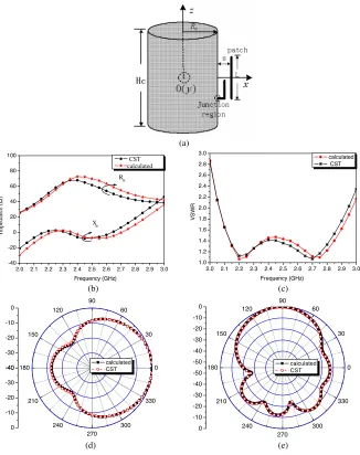
In the same way, the impedance and radiation patterns of an L-probe fed patch antenna mounted on a finite solid conducting cylinder are calculated. As shown in Fig. 5(a), when Rc = 50mm,
Hc= 132 mm, L = 44 mm, W = 44 mm, s= 14 mm, s1 = 9.518 mm, s2 = 20mm, and the operating frequency is about 2.4 GHz, the impedance characteristic, VSWR and radiation patterns are obtained and as shown in Figs. 5(b)–5(e). The results show pretty good agreement with the results of CST software.
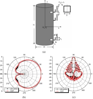
Design parameters of the antenna arrays as following: operating frequency f = 2.4 GHz, DR = 10 0 .0mm, Hc = 875.0mm = 7λ, s= 14.0mm, s1 = 9.5 mm, s2 = 20mm, Sd = 37.0mm, patch sizes: L = 44.0mm and W = 44.0mm. The results are shown in Fig. 6(b)
2.0 2.1 2.2 2.3 2.4 2.5 2.6 2.7 2.8 2.9 3.0 -40
-20 0 20 40 60 80 100
Impedance (
Ω
)
Frequency (GHz) CST calculated
Rin
Xin
2.0 2.1 2.2 2.3 2.4 2.5 2.6 2.7 2.8 2.9 3.0 1.0
1.2 1.4 1.6 1.8 2.0 2.2 2.4 2.6 2.8 3.0
VSWR
Frequency (GHz)
calculated CST
(c) (b)
(a)
0 30 60 90 120
150
180
210
240 270
300 330 -40
-30 -20 -10 0
-40
-30
-20
-10
0
calculated
CST 0
30 60 90 120
150
180
210
240 270
300 330 -50
-40 -30 -20 -10 0
-50
-40
-30
-20
-10
0
calculated CST
(e) (d)
and Fig. 6(c), which are in good agreement with the results of the CST software.
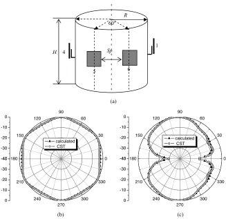
Similarly, the radiation patterns of the six elements patch arrays of L-probe feed mounted on cylinder surface are computed. As shown in Fig. 7(a), the six element patch antenna arrays are equally spaced on the cylinder around along circumference, the parameters of the patch and L-probe are as same as in Fig. 6(a), when R = 86.65 mm, H= 132 mm,Sp= 62.5 mm, and the operating frequency is also about 2.4 GHz. The radiation patterns are calculated and showed in Fig. 7(b) and Fig. 7(c). The results are also in pretty good agreement with the results of CST software.
(a)
0 30 60 90
120
150
180
210
240 270
300 330 -40
-30 -20 -10 0
-40
-30
-20
-10
0
calculated CST
0 30 60 90 120
150
180
210
240 270
300 330 -50
-40 -30 -20 -10 0
-50
-40
-30
-20
-10
0
calculated CST
(b) (c)
1
6 5
4
R
H Sp
60
0 30 60 90 120
150
180
210
240
270
300 330 -40
-30 -20 -10 0
-40
-30
-20
-10
0
calculated CST
0 30 60 90 120
150
180
210
240
270
300 330 -40
-30 -20 -10 0
-40
-30
-20
-10
0
calculated CST
(a)
(b) (c)
o
Figure 7. (a) The six elements patch antenna arrays of the L-probe feed with body of cylinder. (b) The horizontal pattern. (c) The elevation pattern.
5. CONCLUSION
at the junction region between the metal wire and the cylinder surface is carefully derived to extract the singularity and a relatively accurate solution is obtained. The examples above show that the method in this paper is accurate and efficient. The analytical technique developed in this paper can be used to study electromagnetic radiation and scatter problems of wire antenna and array attached to bodies of revolution. ACKNOWLEDGMENT
The work described in this paper was fully supported by National Natural Science Foundation of China (Program No. 60671001). REFERENCES
1. Cao, X., P. Li, K. M. Luk, and C. Liang, “Efficient analysis of L-probe coupled patch antenna arrays mounted on a finite conducting cylinder,” Microwave and Optical Technology Letters, Vol. 41, No. 5, 403–407, 2004.
2. Cao, X., J. Qin, K. M. Luk, and C. Liang, “The efficient analysis model of antenna with bodies of revolution,”Microwave
&Millimetre-wave Symposium of China (2005CNMWS), 420–424, 2005.
3. Harrington, R. F., Field Computation by Moment Methods, New York, Macmillan.
4. Mautz, J. R. and R. F. Harrington, “Radiation and scattering from bodies of revolution,”Appl. Sci. Res., Vol. 20, 405–435, 1969. 5. Andreasen, M. G., “Scattering from bodies of revolution,” IEEE
Trans. Antennas Propagat., Vol. 13, 303–310, 1965.
6. Medgyesi-Mtschang, L. N. and J. H. Mullen, “Radiation and scattering from asymmetrically excited bodies of revolution,”
IEEE Trans. Antennas Propagat., Vol. 24, No. 1, 90–93, 1976.
7. Gedney, S. D. and R. Mittra, “The use of the FFT for the efficient solution of the problem of electromagnetic scattering by a body of revolution,” IEEE Trans. Antennas Propagat., Vol. 38, No. 3, 313–321, March 1990.
8. Raquel, P. L. and F. C. Manuel, “Input impedance of wire antennas attached on-axis to conducting bodies of revolution,”
IEEE Trans. Antennas Propagat., Vol. 36, No. 9, 1236–1243, 1988.
the attachment mode,” Microwave and Optical Technology
Letters, Vol. 22, No. 2, 111–114, 1999.
10. Tarricone, L., M. Mongiardo, and F. Cervelli, “A quasi-one-dimensional integration technique for the analysis of planar microstrip circuits via MPIE/MOM,” IEEE Trans. Microwave