Desingn and Analysis of Ankle Joint Using Different Materials
Ch.Srikanth & P.Prasad (Ph.D)
Department of Mechanical Engineering, gvr&s college of engineering and technology
2 Assistant Professor, Department of Mechanical Engineering, gvr&s college of engineering and technology
ABSTRACT
Total ankle replacement is a procedure in which an injured ankle joint is replaced with a plastic and metal joint. Available data suggest that total ankle replacement has a relatively short lifespan. Presently SS316L, co-cr-mo Alloy, Ti-6Al4V, are used as implant material in ankle replacement surgery. The materials are conventional material, heavier in density which fails within prescribed period and costly. The objective of this study is to analyze stresses on implant of the ankle joint. A three-dimensional finite element method (FEM) model of the implant will be developed for the study. The analysis of the FEM model found stress concentrations in the implant. To obtain the results by considering the different loads exerted by human body weight on ankle joint implants while walking conditions. From the results of analysis on implant, it can be concluded that stainless steel have minimum stresses as compared to alumina but density is heavier considered to Titanium alloy. The ankle replacement material requires less deformation and low density. The low density materials are recommended for better life and performance. Developing a new material with low density Co-cr-mo alloy, finally concluded the suitable material for ankle joint.
Keywords – Finite element method, Stainless steel,
Stress, Titanium alloy, co-cr-mo Total ankle replacement
INTRODUCTION
1.1: Types of Joints in Human Body:
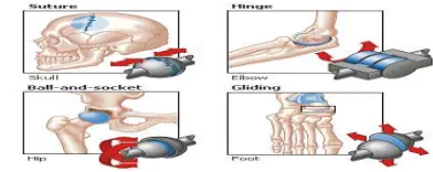
The point where two or more bones meet is called a joint. Joints are classified by their structure or the way they move
Figure 1.1: Various Joints in a Human Body
Suture:
The joints of the skull are known as sutures (top, left). Sutures do not have a wide range of movement. Instead, they allow for growth and very limited flexibility.
Hinge joints: (top, right) allow for movement in one
plane. The hinge joints of the elbow and knee, for example, bend up and down.
Gliding Joint:
Two flat-surfaced bones that slide over one another make up a gliding joint (bottom, right). Gliding joints, such as those in the wrist and the foot, provide for limited movement.
Ball-and-Socket Joints:
These joints allow the greatest range of motion. The ball-and-socket joints of the shoulder and hip, for example, can rotate in
Figure 1.2: Parts of a Joint
Articular Cartilage (Purple):
The end of each bone is covered with articular cartilage. This is a tough material that cushions and protects the ends of the bones. When it degenerates, arthritis develops.
TOTAL ANKLE REPLACEMENT
Ankle replacement or ankle arthroplasty, is a surgical procedure to replace the damaged articular surfaces of the human ankle joint with prosthetic components. This procedure is becoming the treatment of choice for patients, replacing the conventional use of arthrodesis, i.e. fusion of the bones. The restoration of range of motion is the key feature in favor of ankle replacement with respect to arthrodesis.
2.1: History of Total Ankle Replacement (TAR):
The history of total ankle arthroplasties date back to the 1970s with a rise in popularity of total hip and total knee replacement. A total ankle replacement was felt to be an easy thing and several different designs were released. These were cemented prostheses, in general two-part components that were very non-anatomic. With short-term follow-up some of these ankles did well but in intermediate follow-up of even four or five years they began to fail. By the mid 1980s total ankle replacement in the United States was not being done. Many of these ankles were later fused as a salvage procedure. Thus over a fifteen to
twenty year period, ankle fusion was really the only choice for patients with severe arthritis of the ankle.
2.4:Material Properties:
Tab 2.1: Material Properties
DESIGN OF AN ARTIFICIAL ANKLE JOINT
IN CATIA V5 R20
CATIA, stands for Computer Aided Three-dimensional Interactive Application. It is a multi-platform CAD/CAM/CAE commercial software suite developed by the French company Dassault Systems, technically supported worldwide by IBM. Also, CATIA is the most powerful knowledge based and widely used CAD (computer aided design) software of its kind in the world.
The most commonly CATIA users are generally Aerospace, Appliances, Architecture, Automotive, Construction, Consumer Goods, Electronics, Medical, Furniture, Machinery, Mold and Die, and Shipbuilding industries.
In this study, Catia V5 is taken as the primary CAD system not only because of the power and versatility but also due to the increasingly large market share that is being gained by Catia V5.
3.1: Design Process of a 3-Component Mobile Bearing Ankle Joint:
tibial plate, and (2) the interface between the lower surface of the mobile bearing and the facing surface of the talar component. The tibial plate has one flat surface and one surface with two raised cylindrical barrels oriented in the anterior/posterior direction.
The sloped sides are designed to improve the weight bearing characteristics of the talar component. Important factor that should be remembered when designing of artificial ankle joint is bone removal rate should be as less as possible.
If bone removal rate is high further complications will be aroused. Keeping this factor in mind a 3 component mobile bearing artificial ankle joint has been designed on the basis of S.T.A.R (Scandinavian Total Ankle Replacement) ankle.
The S.T.A.R Ankle system includes three functional components. The three principal components of the prosthesis are:
• A metal tibial component
• An ultra high molecular weight polyethylene mobile bearing; and
• A metal talar component
As a result, the process also involves three design steps: • Design of tibial component
• Design of mobile bearing component • Design of talar component
However, data regarding the stability of the artificial ankle on the talus bone and the materials used for the components has been collected and corresponding design changes has been done by considering the suggestions of orthopaedicians.
Various materials that has been used for the components are:
Tibial component: co-cr- mo (ASTM F75) alloy
Mobile bearing component: ultra high molecular weight polyethelene (GUR 1050)
Talar component: co-cr- mo (ASTM F75) alloy
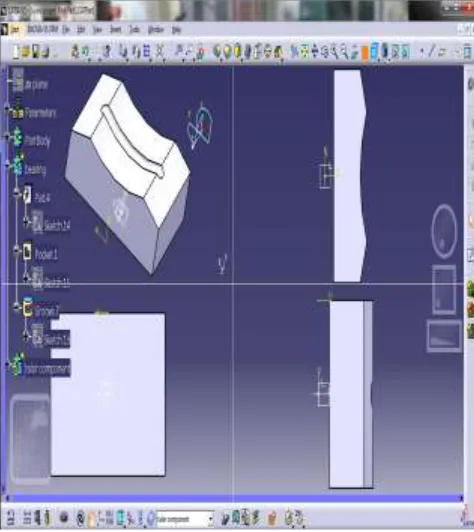
3.1.1: Design of Tibial Component:
When viewed from the top, the tibial plate has a trapezoidal shape. This wedge is shaped to conform to the existing anatomy and, thereby, reduces the need to remove excess bone from inside the joint. On the proximal surface of the tibial plate, two parallel cylindrical barrels are positioned equidistant from the center of the plate running anterior to posterior for bone fixation. These cylinders must be inserted into hard subchondral bone. When viewed from the side, the plate is 2.5mm thick. The distal surface of the plate on which the mobile bearing articulates is flat. The flat surface is designed to match the distal tibial cut.
In this study, dimensions of tibial component are taken based on talar component dimensions and bone removal rate of distal tibia.
Specifications of a Tibial Component:
Figure 3.1: Design of Tibial Component
3.1.2: Design of Mobile Bearing Component:
The proximal surface of the mobile bearing is flat. The distal or talar surface is concave and has a central radial groove running from anterior to posterior.
Specifications of a Bearing Component:
Length of bearing component = 30mm Width of bearing component = 20mm Height of bearing component = 8mm
Width of the groove running from anterior to posterior=2mm
Length of the groove running from anterior to posterior=20mm
Material used- co-cr-mo
Reason for Height of the Bearing Component as 8 mm:
The effect of co-cr-mo thickness on contact pressure was described and analyzed. The study was based on the allowable contact stress during compressive loading from 0 to 60 MPa applied to a typical knee design while changing the meniscus
thickness from 4 to 24 mm. They concluded that there was an inverse relationship between thickness and contact stress. In addition, the study of Bartel et alalso concluded that the stresses were inversely related to the thickness of the alloy. A similar studyfrom Orthoteers Company on wear rate of biomaterials determined that thin polyethylene between 6–8 mm in thickness increases fatigue wear and thereafter determined that the thickness level of the meniscus should be between 8–10 mm.
Figure 3.2: Design of Mobile Bearing Component
3.1.3: Design of Talar Component:
The talar component is designed as an anatomical prosthesis to cover the talar dome, anterior, posterior, and medial and lateral facets, like the tibial plate. The talar component is designed to minimize the amount of bone that must be removed. From the apex of the dome, the walls slope outwards to conform to the normal bone anatomy.
ridge is to constrain the medial/lateral motion of the mobile bearing.
Specifications of Talar Component:
The dimensions of talar component were taken from results of Ankle morphometry on 3D- CT images published by Andrea Hayes,Yuki Tochigi, and Charles L.Saltzman.
1)
T he widt h o f the s uperior talar do me s ur face wa s avera ge d as
29.9 ± 2.6mm (mean ± standard deviation) at the anterior
27.9 ± 3.0mm at middle and
25.2 ± 3.7mm at the posterior portions.
2) The radius of the surface contour on the mid-sagittal section was 20.7 ± 2.6mm.
Both the width and radius were larger in males than in females. Figure 4.3 shows the design of talar component.
Figure 3.3: Design of Mobile Bearing Component
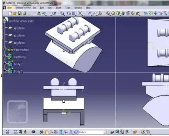
Figure 3.10: Design of Artificial Ankle Joint Similar to STAR in all views
NON-LINEAR STATIC ANALYSIS OF AN ARTIFICIAL ANKLE JOINT
E A group of numerical methods for approximating the governing equations of any continuous system is known as Finite Element Analysis (FEA).
Example of problems that can be treated by FE: • Structural Analysis
• Heat Transfer • Fluid Flow • Mass Transport
• Electromagnetic Potential • Acoustic
4.1: Ansys:
ANSYS is a general purpose software, used to simulate interactions of all disciplines of physics, structural, vibration, fluid dynamics, heat transfer and electromagnetic for engineers. So ANSYS, which enables to simulate tests or working conditions, enables to test in virtual environment before manufacturing prototypes of products. Furthermore, determining and improving weak points, computing life and foreseeing probable problems are possible by 3D simulations in virtual environment. Also, it can work integrated with other used engineering software on desktop by adding CAD and FEA connection modules.
ANSYS can import CAD data and also enables to build geometry with its "pre-processing" abilities. Similarly in the same pre-processor, finite element model (a.k.a. mesh) which is required for computation is generated. After defining loadings and carrying out analyses, results can be viewed as numerical and graphical. It can carry out advanced engineering analyses quickly, safely and practically by its variety of contact algorithms, time based loading features and nonlinear material models.
ANSYS Workbench is platforms which integrate simulation technologies and parametric CAD systems with unique automation and performance. The power of ANSYS Workbench comes from ANSYS solver algorithms with years of experience. Furthermore, the object of ANSYS Workbench is verification and improving of the product in virtual environment.
4.2: Non-Linear Static Analysis:
Static Analysis provides the calculation for the stress state of structures under forces which are constant in terms of time. To date probably this is the most demanded task in the design. By using the module "Static analysis," the engineer can evaluate the allowable stresses in design which is developed, determine drawbacks of the design and make necessary changes (optimize) the product. Static studies calculate displacements, reaction forces, strains, stresses, and factor of safety distribution.
Static analysis can help you avoid failure due to high stresses. Various structural loads and restraints can be specified including force, pressure, gravity, rotational
load, bearing force, torque, prescribed displacement, temperature, etc
Static analysis also allows one to:
take into account the geometric non-linearity;
determine the stress-strain state of temperature effect;
perform calculations of contact problems; Main results of static analysis are as follows:
field of displacements of the structure in nodes of finite-element mesh;
field of strain;
field components of the stress;
energy of deformation;
nodal forces;
field distribution of safety factor;
This information is usually sufficient to predict the behaviour of structures and make a decision how to optimize the geometric shape of the product.
Non-linear behaviour:
A structure is a non linear if the loading causes significant changes in stiffness.
strains beyond the elastic limit
Large deflections
Contact between two bodies
4.3: Methodology:
The flow chart of the process using Computer Aided Engineering (CAE) tools is as follows:
Computer modeling, mesh generation
Definition of materials properties.
Assemble of elements
Boundary conditions and loads definedSolution using the required solver
1. Divide / discretize the structure or continuum into finite elements. This istypically
done using mesh generation program called pre-processor.
Ex.: Nodal loads associated with all elements, deformation states that are allowed.
Figure 4.2: Stress vs Strain
2. Assemble the elements to obtain the model
3. Specify the load and boundary conditions. Constraints, force, known temperatures, etc.
4. Solve simultaneous linear algebraic equations to obtain the solutions.
4.3.1: System Configuration:
In the present work, the
computational numerical analysis is done using ANSYS version 13.0 running on XPS system, having 4GB ram and 500GB hard disk withWindows 7 operating system.
4.3.2: Problem Definition:
There is currently much interest in deformation analysis of artificial joints having multiple components. One such case is the design and analysis of the artificial ankle joint which is a three component design having two contacts. In order to accurately model the deformations of the artificial ankle joint, non-linear
finite-element procedures are need to be employed. With the advent of the development of contact analysis, it is appropriate to apply the contact analysis technique in the analysis of the artificial ankle joint. Thus the effect of the system with contact has been studied.
4.3.3: Tasks to be Done:
1. Each part in the ankle component has to be capable of holding both tensile and
compressive loads successively.
2. Stresses and deflection should be within the permissible limits.
3. Perfect contact pair should be formulated.
4. Parts of the component should always be bonded to each other.
5. Converges of the model should be achieved.
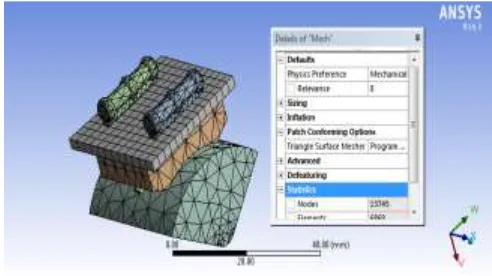
4.4: Meshing:
The design that is saved in igs format is imported in Ansys work bench and engineering data is applied and by generating mesh ,nodes and elements are created ,as shown in the below figure nodes are 13745 and elements are 6868
Figure 4.4: Meshing
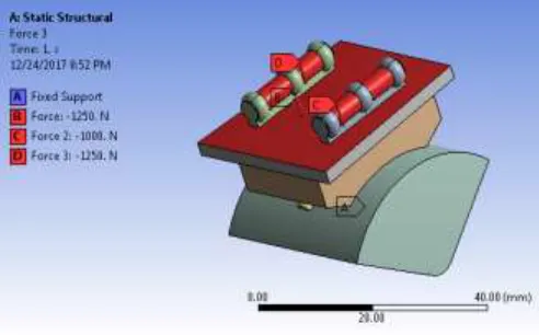
4.5: Boundary Conditions:
bench bottom TALAR is fixed and appl apply different forces 2000N,2500N,3000N,3500N ON TIBIA
Figure 4.5: Force Applied on Ankle Joint 2000N
Figure 4.6: Force Applied on Ankle Joint 2500N
Figure 4.7: Force Applied on Ankle Joint 3000N
Figure 4.8: Force Applied on Ankle Joint 3500N
RESULTS AND DISCUSSIONS
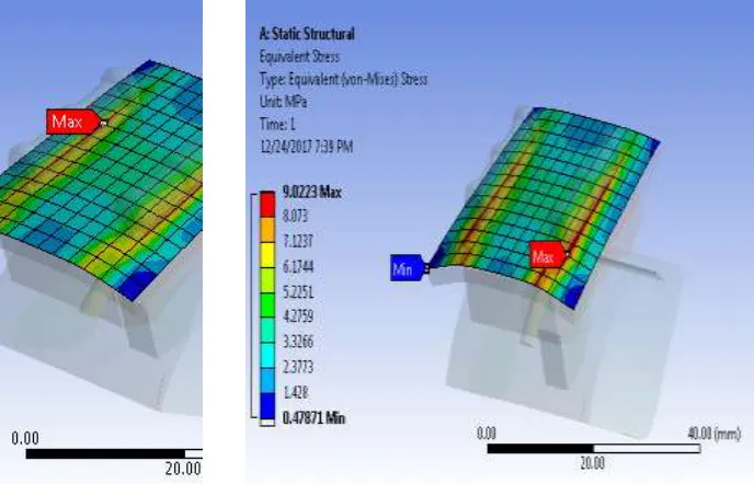
We are analyzing ankle joint and finding stress, deformation, by using different materials and different load conditions as show in below figures and after observing all the max values of every material we are concluding the material which is suitable for ankle joint .
5.1:Co-Cr-Mo Material:
When Patient Weight is 60kg at 2000N:
Figure 5.1: Von-Misses Stress at 2000N
5.1.1:When Patient Weight is 75kg:
Figure 5.3: Von-Misses Stress at 2500N
5.1.2: When Patient Weight is 85kg:
Figure 5.5: Von-Misses Stress at 3000N
5.1.3: When Patient Weight is 100kg:
Figure 5.7: Von-Misses Stress at 3500N
5.2: Steel Material:
5.2.1 when Patient Weight is 60 kg:
5.2.2: When Patient Weight is 75 kg:
Figure 5.11: Von-Misses Stress at 2500N
5.2.3: When Patient Weight is 80kg:
Figure 5.13: Von-Misses Stress at 3000N
5.2.4: When Patient Weight is 100kg:
Figure 5.15: Von-Misses Stress at 3000N
5.3: TI6AL4V Material:
5.3.1: When Patient Weight is 60kg:
Figure 5.17: Von-Misses Stress at 2000N
5.3.2: When Patient Weight is 75kg:
Figure 5.19: Von-Misses Stress at 2500N
5.3.3: When Patient Weight is 85kg:
Figure 5.21: Von-Misses Stress at 3000N
Figure 5.23: Von-Misses Stress at 3500N
5.4: Graphs:
The below 4 graphs shows that ,with increase in loads(2000N,2500N,3000N,3500N) stress will increase in different materials, like co-cr-mo, steel,Ti6alv .co-cr mo material has least stress value compared to another materials as shown in the graph 1.1
Graph 5.1: Stress Graph 2000N
The below 4 graphs shows that ,with increase in loads(2000N,2500N,3000N,3500N) total deformation will increase in different materials, like co-cr-mo, steel,Ti6alv .Co-cr mo material has least deformation value compared to another materials as shown in the graph 1.1
Graph 5.5: Total Deformation Graph at 2000N
5.5: Modal Analysis:
5.5.1: Co-Cr-Mo Material:
5.6: Modal Analysis Final Results:
Tab 5.1: Co-Cr-Mo Material Modal Analysis Results
Tab 5.2: Steel Material Modal Analysis Results
CHAPTER 6
CONCLUSION
Diligent study of normal ankle biomechanics and review of previous implant failures has led to the development of a new generation of implants. This improvement coupled with improved cementless fixation, has led to prosthetic designs with decreased failure rates. Increased awareness and adequate surgeons training are probably the key factors to transform TAR to a promising alternative to ankle arthrodesis. However, appropriate selection of patients remains a cornerstone for a successful ankle replacement.
In this study, the design approach for a 3-component mobile bearing artificial ankle joint using CATIA software has been developed. Some design changes in talar component were made when compared to STAR (Scandinavian Total Ankle Replacement) ankle. The design of an artificial ankle joint similar to STAR ankle has also been carried out.
By introducing the contact pair in between the components, non-linear static analysis of an artificial ankle joint has been done using ANSYS software.
Normally the load acting on the ankle joint of human lower limb is 5–10 times of body weight.
The analysis is carried out by walking condition varying the load on the ankle from 2000-3500 Newton’s. It was found that, at 3500 Newtons of load, the Von Mises stresses are found to be 8.433 MPa on co-cr-mo material, deformation is 0.0018mm. Steel material have high stress and deformation in every load condition compared to the co-cr-mo material.
In conclusion, currently, selected patients with painful ankle prosteoarthritis can be offered a total ankle replacement not only in U. S but also in INDIA.
static and modal analysis done Finally concluded it is that co-cr-mo material is suitable for ankle joint replacement .
Future Scope of the Work:
There are several areas where further work clearly needs to be done.
1. Further designs should be directed toward reducing ligament strain, restoring the
normal axis of rotation and maintaining mobile bearing stability.
2. Further work can be carried out for dynamic analysis from which wear rate and the life span of the implant can be estimated.
REFERENCES