Broadband Circularly Polarized Cross Shaped Slot Antenna
with an Improved Feedline
Kwame O. Gyasi, Guangjun Wen, Yongjun Huang, E. Affum, and Wei Hu
Abstract—A broadband circularly polarized cross-shaped slot antenna with a parasitic cross-shaped patch and an improved feedline is proposed for wireless applications between 3–6 GHz. In order to achieve a wide axial ratio bandwidth that is totally enclosed within a wide impedance bandwidth, a wide cross slot in the ground plane and an L-shaped strip attached to the lower section of the feedline are employed. This design presents a technique for achieving an axial ratio (AR) bandwidth for a single fed antenna that is wider than most of the single fed slot antennas that currently exist. The proposed antenna with a compact size of 30 mm×30 mm×1.6 mm is fabricated and measured. A measured broadside 3 dB axial ratio bandwidth of 68.7% (3.1–6.35 GHz) within a measured impedance bandwidth of 84.1% (2.61–6.4 GHz) for S11 < −10 dB is obtained. A measured peak gain of 3.8 dBi is obtained within the axial ratio bandwidth. The obtained results show that the antenna can be used for wireless devices that operate in the 3.3–3.8 GHz and 5.15–5.35/5.725–5.825 GHz (specified by IEEE 802.11a) bands for wireless standard technologies.
1. INTRODUCTION
As a result of the growth of the wireless communication market, both current and future applications and systems such asWireless Metropolitan Area Network Air Interface(WiMAX) require high data rates and as such, wide bandwidths [1]. Due to the decrement in size of the devices that operate such applications, antennas with compact sizes, low profile, low cost and very broad bandwidths are required. The authors in [1–3] proposed miniaturized antennas for different wireless applications. In [1], a particle swarm optimizer was used to optimize the geometry of a pre-fractal koch like printed antenna. A numerical technique which is also based on a particle swarm optimizer was employed for the synthesis of a pre-fractal dual band monopolar antenna in [2]. Whereas in [3], a multi-phased stochastic based approach for the design of an integrated multiband antenna system was described. However, the antennas in [1–3] are linearly polarized with the exception of the GPS antenna in [3] which is a non planar Archimedean spiral antenna.
The use of circularly polarized (CP) antennas [4–21] has gained much momentum in the wireless engineering community due to their ability to suppress multipath fading and doing away with the need for arranging the orientation of transmit and receive antennas. Also, CP antennas provide better mobility and immunity to adverse weather conditions than linearly polarized antennas.
CP can be realized in single feed microstrip antennas by introducing perturbations in the antenna structure. Such perturbations include introducing RF switch controlled rectangular discontinuities on patches [4]; using a feeding mechanism made up of a hook shaped feed line and Γ-shaped slots in a patch antenna [5]; employing cross shaped slots in patch antennas [6, 7]; adding stubs and notches to square slots [8]; inserting grounded inverted L strips in the radiating slots of slot antennas [9, 10]; using
Received 5 February 2017, Accepted 18 May 2017, Scheduled 28 May 2017
* Corresponding author: Kwame Oteng Gyasi (kermaabar@yahoo.com).
a lightening shaped feedline [11, 12]; using an L-slot in place of the traditional rectangular, circular or square slot of a slot antenna [13, 14]; improving the ground plane by adding stubs to it or creating slots in it [15–19] or by embedding a pair of hat shaped patches in an annular ring slot and employing a deformed feedline [20]. However, most of the existing antennas posses large sizes or narrow axial ratio bandwidths (ARBW) that do not cover enough wireless applications.
In this paper, a new CP cross-shaped slot antenna with an improved feedline for wide axial ratio bandwidth is presented. The antenna is designed to cover wireless applications between 3–6 GHz and has a size of 30 mm×30 mm×1.6 mm. A 3 dB ARBW of 68.7% within a wide−10-dB impedance bandwidth of 84.1% is achieved. The proposed antenna is compact and can be used for wireless applications like WiMAX and WLAN within the 3–6 GHz band. All simulations in this paper were undertaken with HFSS 14 which is based on FEM.
2. ANTENNA STRUCTURE AND DESIGN
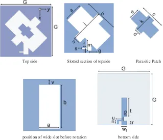
Figure 1 illustrates the geometry of the proposed broadband circularly polarized cross-shaped slot antenna. The antenna is printed on a square FR4 dielectric substrate with a side length of G, a thickness of 1.6 mm, loss tangent of tanδ= 0.02 and a dielectric constant ofεr = 4.4.
The square ground plane with a side length ofGis placed on the top side of the substrate, whereas the feedline with a size of (t+u+r)×wf is placed on the other side of the same substrate. The radiating slot in the ground plane is made up of two intersecting rectangular slots that are rotated at an angle of 45◦ and 135◦ respectively to form a cross-shaped slot similar to the structure proposed in [21]. The 45◦ rotated slot has a dimension ofb×a, whereas the 135◦ rotated slot has a size ofj×h. The 45◦ rotated slot is asymmetrically positioned in the center of the ground plane with a distance ofv from the top end of the antenna before rotation as shown in Fig. 1. The generation of the two orthogonal modes with equal amplitude and a 90◦ phase difference required for CP generation is principally attributed to these intersecting rotated slots. Two rectangular slots of sizesm×wf and f×sare etched in the lower part of the ground plane. An L-shaped strip with a size off×sfor the horizontal section andn×sfor the
position of wide slot before rotation bottom side
Top side Slotted section of topside Parasitic Patch
vertical section is attached to the feedline. Also, a rectangular slot with a size ofu×p is etched in the lower section of the feedline. The feedline and the two additional rectangular slots in the ground plane enhance the impedance bandwidth as well as the ARBW. The dimensions of the proposed antenna are given in Table 1.
Table 1. Dimensions of the proposed antenna.
Parameter G a b c d e
Value (mm) 30 12 25.4 9 2.4 3.8
Parameter f g h i j k
Value (mm) 2.5 1.2 4.8 2.3 20 6
Parameter s m n p r t
Value(mm) 0.8 7 1.7 1.5 2.5 11
Parameter u v wf
Value(mm) 2.5 3.3 3
3. SIMULATION RESULTS AND DISCUSSION
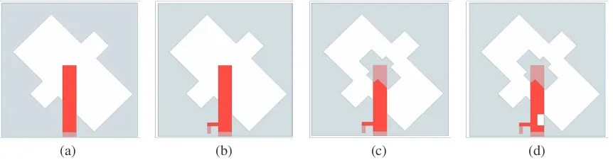
The evolution of the design process of the proposed antenna is shown in Fig. 2. Axial ratio (AR) referred to in all the figures presented in this paper refer to the axial ratio simulated or measured in the +z
direction (theta = 0◦, phi = 0◦).
(a) (b) (c) (d)
Figure 2. Antenna evolution. (a) Antenna I. (b) Antenna II. (c) Antenna III. (d) Antenna IV.
As depicted in Fig. 2, Ant. I consists of a wide cross slot and a rectangular slot in the ground plane as well as a microstrip feedline; Ant. II has Ant. I’s configuration in addition to a horizontal slot in the ground plane and an inverted L-shaped strip attached to the microstrip feedline; Ant. III consists of Ant. II’s configuration and a parasitic patch with its edges parallel to that of the cross slot; and Ant. IV contains Ant. III’s configuration in addition to a rectangular slot in the feedline.
All the antenna parameters are optimized based on a parametric analysis undertaken in HFSS 14 to achieve a maximum ARBW which is totally enclosed by a wide impedance bandwidth. The simulated
(a) (b)
Figure 3. Simulated (a) S11, (b) axial ratio; for antennas I–IV.
(a) (b) (c) (d)
Figure 4. Simulated surface current distribution of Antenna V at 4.5 GHz for angular times. (a)
ωt= 0◦, (b)ωt= 90◦, (c)ωt= 180◦, (d)ωt= 270◦.
impedance bandwidth do not cause the antenna to operate as a CP antenna in the WLAN 5.8 GHz band. A cross shaped patch (parasitic patch) is placed in the center of the wide cross slot to perturb the magnetic current distribution within the slot so as to improve the ARBW [20]. It is seen in Fig. 3 that Ant. III has its impedance bandwidth slightly shifted to the left. This is as a result of the parasitic patch increasing the current path of the antenna [22]. Ant. III achieves an ARBW of about 2.93 GHz (3.02 GHz–5.95 GHz) within an impedance bandwidth of about 3.9 GHz (2.61 GHz–6.5 GHz). However, it was realized from the simulation that the AR values around 5 GHz was very close to the 3 dB threshold and could further deteriorate as a result of measurement or fabrication errors. This could result in the antenna losing its CP functionality in the high frequency range. A slot was therefore placed in the feedline to improve the AR values in the high frequency range. The crossed slot can thus be considered as the perturbation structure that causes CP whereas the parasitic patch and the improved feedline are employed for axial ratio bandwidth enhancement. The results of Ant. IV are discussed in the next section.
The time varying surface current distribution on Ant. IV at 4.5 GHz is simulated to show the mechanism of CP generation by the proposed antenna. The simulation results of surface current distribution (Jsurf) on Ant. IV are illustrated in Fig. 4. As observed, the antenna radiates left-hand circular polarization (LHCP) in thez >0 direction sinceJsurf is seen to move in the clockwise direction as the angular time moves from 0◦ to 270◦. The reverse thus holds true for thez <0 direction where a right-hand circular polarization (RHCP) wave is radiated.
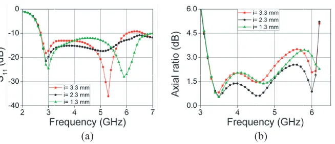
A parametric study is undertaken to show the effect of the antenna’s dimensions on the S11 and axial ratio. It is worth mentioning that only one parameter is changed at a time while the others maintain the dimensions provided in Table 1.
(a) (b)
Figure 5. Simulated (a) S11, (b) axial ratio; for variations ofb.
(a) (b)
Figure 6. Simulated (a) S11, (b) axial ratio; for variations ofc.
(a) (b)
Figure 7. Simulated (a) S11, (b) axial ratio; for variations ofi.
is observed to hold true when b is increased to 26.4 mm. The decrease in S11 bandwidth is mainly because of the ineffective coupling between the feedline and the radiating slot when the size of the slot is decreased.
Figure 6 depicts the effect of the parasitic patch length (c) on the antenna’s performance. It can be observed that the patch length has a minor effect on the antenna’s impedance bandwidth with slight changes in the upper frequency range. It is seen that when the length of c is 8 mm, the antenna loses its CP functionality between 5.5 GHz and 5.7 GHz. When a value of 10 mm is chosen, it is observed that the antenna’s AR values in the upper frequency range are close to 3 dB which is not ideal taking into consideration fabrication and measurement errors. In order to achieve an optimum ARBW and AR values, a length of 9 mm is chosen.
(a) (b)
Figure 8. Simulated (a) S11. (b) Axial ratio; for variations ofv.
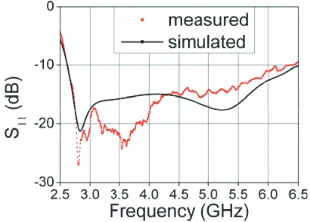
Figure 9. Simulated and measuredS11 of the proposed antenna.
Figure 10. Simulated and measured axial ratio of the proposed antenna.
Figure 11. Simulated and measured axial ratio of the proposed antenna.
observed that the position of this strip has a major effect on the axial ratio. This is to be expected as the strip was employed to perturb the current distribution on the antenna in order to enhance the ARBW.
The effect of the position of the 45◦ rotated wide slot before rotation (v) on the antenna’sS11 and AR is illustrated in Fig. 8. It is observed that the position of this slot has an adverse effect on both the S11 and the AR. When v is decreased with respect to the optimum value of 3.3 mm, it is realized that both the S11and AR bandwidths are reduced. It is also realized that the S11 intensity is reduced. When vis increased with respect to the optimum value of 3.3 mm, it is observed that the S11 intensity is increased whereas the AR bandwidth decreases.
4. EXPERIMENTAL RESULTS
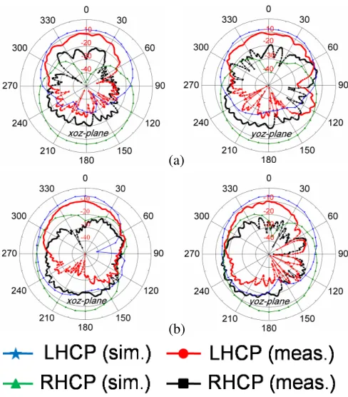
which is in reasonable agreement with the simulated −10 dB impedance bandwidth of 85.4% (2.61– 6.5 GHz). It is observed from Fig. 11 that the antenna achieves a measured 3 dB ARBW of 68.7% (3.1–6.35 GHz) which is in close agreement with the simulated 3 dB ARBW of 69.95% (3.03–6.29 GHz). The proposed antenna is seen to have a moderate broadside gain within the overlapped frequency which peaks at 3.8 dBi and a peak efficiency of about 80% as seen in Figs. 12(a) and (b). It is seen from Fig. 13 that the antenna radiates a bidirectional beam with LHCP in thez >0 direction and RHCP in thez <0 direction. It is observed that the measured and simulated radiation patterns have significant discrepancies between them. This is attributed to the effects of the SMA connector and fabrication tolerances as well as the losses associated with the substrate.
For comparison, the antenna sizes and bandwidths of some CP antennas are summarized in Table 2. In this table, fc represents the center frequency of the ARBW and λ0 is the corresponding free-space wavelength. It is realized from Table 2 that our proposed design offers a better tradeoff between size and ARBW than the referenced antennas.
(a) (b)
Figure 12. (a) Simulated and measured gain. (b) Measured Efficiency.
(a)
(b)
Figure 13. Simulated and measured radiation patterns of the proposed antenna both inxoz-plane and
Table 2. Comparison between ARBW and sizes of some existing CP antennas and the proposed antenna.
Ref. fc (GHz) 3-dB ARBW(%) Ant. Area (mm×mm), (λ20)
[6] 1.99 18 50×50, 0.11
[7] 2.26 53 75×46, 0.20
[8] 2.59 10.8 80×80, 0.48
[9] 3.5 85 60×60, 0.49
[10] 5.9 32.2 60×60, 1.39
[11] 2.745 48.8 60×60, 0.3
[12] 2.22 30.6 60×60, 0.197
[13] 6.75 51.8 20×20, 0.20
[14] 2.84 46.5 82×82, 0.6
[15] 1.385 35.4 79×79, 0.13
[16] 5.9 44.9 24×25, 0.23
[17] 1.965 18.8 70×70, 0.21
[18] 5.2 35.7 25×25, 0.18
[19] 3.7 27 50×50, 0.38
[20] 1.637 65.6 100×100, 0.29
[21] 1.8 25.6 100×100, 0.36
Prop. 4.725 68.7 30×30, 0.22
5. CONCLUSION
A new CP slot antenna with a cross slot and an improved feedline has been presented. The cross slot can provide the necessary perturbation for the CP operation. Moreover, the use of an L-strip attached to the feedline, a parasitic patch in the center of the wide cross slot and additional slots in the feedline and ground plane can improve the impedance and 3-dB AR bandwidths. The evolution of the antenna has been used to explain the theory behind the operation of the antenna. The proposed antenna is fabricated and measured. In addition to the simple configuration and compact size of 30×30×1.6 mm3, measured results show that the proposed antenna achieves a −10 dB impedance bandwidth of 84.1% (2.61–6.4 GHz) and a 3-dB AR bandwidth in the broadside direction of 68.7% (3.1–6.35 GHz) which covers wireless applications such as the 3.3–3.8 GHz and 5.725–5.825 WiMAX as well as 5.150–5.350 WLAN. The proposed antenna is designed on an inexpensive FR4 dielectric substrate and has a measured peak antenna gain of around 3.8 dBi in the operating band.
ACKNOWLEDGMENT
This work was supported in part by the National Natural Science Foundation of China under project contract No. 61371047, in part by Guangdong Provincial Science and Technology Planning Program (Industrial High-Tech Field) of China under project contract No. 2016A010101036, and in part by Sichuan Provincial Science and Technology Planning Program (Technology Supporting Plan) of China under project contracts No. 2016GZ0061.
REFERENCES
1. Azaro, R., G. Boato, M. Donelli, A. Massa, and E. Zeni, “Design of a prefractal monopolar antenna for 3.4–3.6 GHz Wi-Max band portable devices,”IEEE Antennas and Wireless Propagation Letters, Vol. 5, 113–119, 2006.
2. Azaro, R., F. De Natale, M. Donelli, E. Zeni, and A. Massa, “Synthesis of a prefractal dual-band monopolar antenna for GPS applications,”IEEE Antennas and Wireless Propagation Letters, Vol. 5, 361–364, 2006.
3. Azaro, R., F. G. B. De Natale, M. Donell, A. Massa, and E. Zeni, “Optimized design of a multifunction/multiband antenna for automotive rescue systems,”IEEE Transactions on Antennas
4. Donelli, M. and P. Febvre, “An inexpensive reconfigurable planar array for Wi-Fi applications,”
Progress In Electromagnetics Research C, Vol. 28, 71–81, 2012.
5. Lai, H. W., K. M. Mak, and K. F. Chan, “Novel aperture-coupled microstrip-line feed for circularly polarized patch antenna,”Progress In Electromagnetics Research, Vol. 144, 1–9, 2014.
6. Li, L., J. Li, B. He, S. Zhang, and A. Zhang, “A compact circularly polarized microstrip antenna with bandwidth enhancement,”Progress In Electromagnetics Research Letters, Vol. 61, 85–89, 2016. 7. Chen, J. M. and J. S. Row, “Wideband circularly polarized slotted-patch antenna with a reflector,”
IEEE Antennas and Wireless Propagation Letters, Vol. 14, 575–578, 2015.
8. Wu, J., X. Ren, Z. Li, and Y. Yin, “Modified square slot antennas for broad-band circular polarization,” Progress In Electromagnetics Research C, Vol. 38, 1–14, 2013.
9. Felegari, N., J. Nourinia, C. Ghobadi, and J. Pourahmadazar, “Broadband CPW-fed circularly polarized square slot antenna with three inverted-L-shape grounded strips,” IEEE Antennas and
Wireless Propagation Letters, Vol. 10, 274–277, 2011.
10. Pourahmadazar, J., C. H. Ghobadi, J. Nourinia, N. Felegari, and H. Shirzad, “Broadband CPW-fed circularly polarized square slot antenna with inverted-L strips for UWB applications,” IEEE
Antennas and Wireless Propagation Letters, Vol. 10, 369–372, 2011.
11. Sze, J.-Y., C.-I. G. Hsu, Z.-W. Chen, and C.-C. Chang, “Broadband CPW-fed circularly polarized square slot antenna with lightening-shaped feedline and inverted-L grounded strips,” IEEE
Transactions on Antennas and Propagation, Vol. 58, No. 3, 973–977, March 2010.
12. Sze, J.-Y., J.-C. Wang, and C.-C. Chang, “Axial-ratio bandwidth enhancement of asymmetric-CPW-fed circularly-polarised square slot antenna,” Electronics Letters, Vol. 44, No. 18, August 2008.
13. Ellis, S. M., J. J. Kponyo, and A.-R. Ahmed, “A compact wideband circularly polarized L-slot antenna edge-fed by a microstrip feedline for C-band applications,” Progress In Electromagnetics
Research Letters, Vol. 65, 95–102, 2017.
14. Yang, S.-L. S., A. A. Kishk, and K.-F. Lee, “Wideband circularly polarized antenna with L-shaped slot,” IEEE Transactions on Antennas and Propagation, Vol. 56, No. 6, 1780–1783, 2008.
15. Wang, K., H. Tang, R. Wu, and C. Yu, “Compact broadband circularly polarized monopole antenna for global navigation satellite system (GNSS) applications,”Progress In Electromagnetics Research C, Vol. 69, 27–36, 2016.
16. Zhang, L., Y. Jiao, Y. Ding, B. Chen, and Z. Weng, “CPW-fed broadband circularly polarized planar monopole antenna with improved ground-plane structure,”IEEE Transactions on Antennas
and Propagation, Vol. 61, No. 9, 4824–4828, 2013.
17. Sze, J.-Y., K.-L. Wong, and C.-C. Huang, “Coplanar waveguide-fed square slot antenna for broadband circularly polarized radiation,” IEEE Transactions on Antennas and Propagation, Vol. 51, No. 8, 2141–2144, August 2003.
18. Shokri, M., V. Rafii, S. Karamzadeh, Z. Amiri, and B. Virdee, “Miniaturised ultra-wideband circularly polarised antenna with modified ground plane,” Electronics Letters, Vol. 50, No. 24, 1786–1788, November 2014.
19. Jan, J.-Y., C.-Y. Pan, K.-Y. Chiu, and H.-M. Chen, “Broadband CPW-fed circularly-polarized slot antenna with an open slot,” IEEE Transactions on Antennas and Propagation, Vol. 61, No. 3, 1418–1422, March 2013.
20. Sze, J. Y. and W. H. Chen, “Axial-ratio-bandwidth enhancement of a microstrip-line-fed circularly polarized annular-ring slot antenna,” IEEE Transactions on Antennas and Propagation, Vol. 59, No. 7, 2450–2456, July 2011.
21. Tian, C., Y.-C. Jiao, and W.-L. Liang, “A broadband circularly polarized square slot antenna,”
Progress In Electromagnetics Research Letters, Vol. 50, 29–34, 2014.