A Very Compact Quintuple Band Bandpass Filter Using Multimode
Stub Loaded Resonator
Abdul Sami1 and MuhibUr Rahman2, *
Abstract—This paper presents a very compact quintuple band bandpass filter utilizing multimode stub loaded resonator. A single symmetric resonator is loaded with a short ended stub at the middle along with four pairs of open-ended stubs. The open-ended stubs are folded towards each other in order to make the design more compact and improve the selectivity of the bandpass filter. Because of symmetry, the circuit is analyzed with the help of even-odd mode analysis. The proposed bandpass filter operates at GSM-900, LTE2300, WiMAX (3.5 GHz), WLAN (5.4 GHz), and RFID (6.8 GHz). The operating mid frequencies of quintuple-band BPF are 0.96 GHz, 2.22 GHz, 3.58 GHz, 5.41 GHz, and 6.64 GHz, and the corresponding 3 dB Fractional Bandwidths are 36.03%, 20.95%, 7.27%, 8.57%, and 3.37%, respectively. The implemented resonator is analyzed in detail, and the formulation is developed in this regard. The proposed filter is developed based on the analysis and is simulated and fabricated. The simulation and measurement responses agree very well.
1. INTRODUCTION
Planar multi-band bandpass filters can be developed using multiple identical resonators. However, the filter needs more sections for sharp cutoff frequency response, which considerably increase the circuit size of the bandpass filter [1]. To solve this problem, in [2] they develop a microstrip hairpin resonator, which reduces the overall circuit size and also provides sharp cutoff. In fact, this kind of resonator is smaller than the conventional hairpin resonator, which is actually the variation of SIRs. The advantage of the stepped impedance resonator is its compactness by adjusting the impedance ratio [3]. In [4], a bandpass filter is implemented using a pair of coupled hairpin resonators along with inter-digital capacitors to get tunable bandwidth and predicted transmission zeros in the stopband. In spite of the presence of transmission zeros, the response of the filter has poor frequency selectivity. Extensive work on dual-band bandpass filters has been described on microstrip using stub loaded resonators (SLRs) in [5–9]. All of these designs have shown a very narrow bandwidth with only two passbands. A dual bandpass filter with more control on passbands and resonant frequencies is presented using a quad-mode stub loaded resonator in [10]. However, this design has narrow bandwidth and low-frequency selectivity of the second band due to the inappropriate position of higher transmission zeros.
To increase the passbands, researchers have investigated SLR in [11], by presenting a new square ring short SLR that has the capability of three passbands with sharp skirt selectivity. In [12], spiral-shaped resonators are used to get a tri-band response, but the design possesses a larger circuit size due to the insertion of multiple resonators. Moreover, the presented filter has low insertion loss and reduced frequency selectivity due to the absence of transmission zeros in the stopbands. Another triband filter is realized using frequency coupling structure with loaded SIRs in [13]. The design has narrow passbands with reduced frequency selectivity between the second and third bands because of no transmission zero
Received 4 April 2019, Accepted 12 June 2019, Scheduled 24 June 2019
* Corresponding author: MuhibUr Rahman ([email protected]).
1 Department of Electrical Engineering, National University of Sciences and Technology, Islamabad, Pakistan. 2 Department of
in the stopband. In order to solve the narrow passbands problem, a tri-band with relatively broader passband is designed in [14] using a sextuple-mode resonator. The sextuple-mode resonator has a very complex design and larger circuit area due to many loaded stubs. A very complex and switchable quad bandpass filter is realized with the help of switching circuits in [15]. Multiband response is achieved by implementing different configurations using SIRs in [16]. They create more passbands by using higher modes which in turn increase the losses and circuit area of the design. Recently, a tri-band bandpass filter is presented using SLRs stated as stub loaded dual mode resonators [17]. One inner and outer stub inserted resonators are utilized to achieve the tri-band response. They create the third passband with the help of intra-resonator coupling.
It is very challenging to achieve quad-band bandpass filter response because it is hard to achieve good matching and low insertion loss for multiple passbands, simultaneously. Therefore, very limited work is reported on quad-band bandpass filter in the existing literature. In order to further increase the passbands, in [18] they propose a quadruple bandpass filter utilizing shorted stub with E-shaped resonators. The presented filter has the capability to operate at 2.4, 3.5, 5.2, and 5.8 GHz, simultaneously by utilizing the inter-resonator coupling successfully. Assembled resonators technique is used to implement quad-band bandpass filter in [19], and quad mode stub loaded resonator is utilized to get quad-band bandpass filter in [20], but the presented designs have complex structures with large circuit size and narrow passbands. Another novel technique using stub loaded half wave SIRs and stub loaded quarter wave SIRs is employed to get the quad-band spectrum in [21]. The main purpose of the technique was to control the bandwidths. Moreover, in [22] multiband filters with tunable center frequencies are developed utilizing novel T-shaped stub loaded SIRs to implement multiband filters with tunable center frequencies [22]. The middle frequency can be tuned with the help of impedance ratios and length ratios of the loaded open stubs. Also, a wideband bandpass filter is designed in [23, 24] having the capability to operate from 3.1 to 10.6 GHz frequency range. Maximum transmission zeros are achieved in [25] by analyzing the loaded and unloaded Q-factor in triple bandpass filter. Also, a meander bandpass filter is designed in [26] to operate at 7.65 GHz.
Quintuple bandpass filters are only developed in [27–29]. In [27], a quintuple response is made possible by combining five similar bandpass filters having varied sizes which make the circuit complicated with greater insertion loss. In [28], the quint passbands are achieved by combining two structures and then loading each structure with five resonators. The presented filter is designed by the combination of two main resonators, which make them bulky with the size of 0.21λg×0.19λg. Moreover, the presented
filter also greatly suffers from the inter-resonator coupling with very complex geometry. Recently, a quintuple bandpass filter is designed using the concept of mixed coupling in [29]. The filter has the capability to operate at 1.27/3.22/5.87/7.51/9.74 GHz frequency bands with the corresponding size of 0.11λg ×0.34λg.
In this manuscript, we present a very compact quintuple band bandpass filter utilizing multimode stub loaded resonator (MSLR). The proposed bandpass filter has the capability to operate at GSM-900, LTE2300, WiMAX (3.5 GHz), WLAN (5.4 GHz), and RFID (6.8 GHz), simultaneously. The proposed MSLR is also analyzed using even and odd mode analysis, and the corresponding circuits with resonance frequencies are developed in each case. Improvements in terms of circuit size reduction, wider bandwidth, high bandpass selectivity, and low insertion loss are observed in comparison with other reported works while only one multi-mode resonator is used for the first time to achieve the quint bandpass response. The proposed filter is simulated and fabricated for validation purpose. The simulation and measurement responses agree very well. The proposed filter will be one of the promising candidates for future multiband transceivers. Also, the proposed filter is very compact, and its application in terms of integrating with other components (antennas) by creating multiple passbands will be a feasible solution for future wireless communication applications.
2. RESONATOR ANALYSIS
A basic MSLR comprising one shorted stub and eight open stubs is provided in Figure 1. It is further decomposed into even and odd mode circuits as shown in Figures 1(b) and (c), respectively. This even
(a)
(b) (c)
(d) (e)
(f) (g)
(h) (i)
(j) (k)
(l) (m)
and odd mode can be further decomposed into five resonant circuits as shown from Figure 1(d) to Figure 1(m), respectively. Now, the resonant odd and even mode frequencies and the corresponding input admittances are calculated using microwave network circuit theory according to which the input admittance is given by Equation (1).
Yin=YoYL
+jYotanθ
Yo+jYLtanθ
(1)
whereθ=βL is the electrical length of the stubs, and β is the propagation constant. Now considering Figure 1(d) to calculate the input admittance Yin,even1 and resonant frequency feven1. In this regard, we first take stub ‘Ls’ which is short ended thusYL=∞. By putting the value of YLand Y0 =Ys/2 in
Equation (1), we obtain the input admittance Yin,s of the short ended stub ‘Ls’ as in Equation (2).
Yin,s=−j
Ys
2
cotθs (2)
Now, Yin,swill act as YL for the rest of the transmission line as in Figure 1(d). By placingY0 =Y1 and correspondingYin,svalue in Equation (1), we obtain Yin,even1 as Equation (3).
Yin,even1=−jY1Ys−
2Y1tan(θ1+θ2+θ3+θ4+θ5) tan(θs) 2Y1tan(θs) +Ystan(θ1+θ2+θ3+θ4+θ5)
(3)
To find the mode frequency for the transmission line circuit given in Figure 1(d), place θs = βLs, θ1 = βL1, θ2 = βL2, θ3 = βL3, θ4 = βL4, θ5 = βL5, β = 2λgπ in Equation (3) and assume that
Y s
2 =Y1.
At resonanceYin,even1 = 0, introduce this information in Equation (3) to get the resonant frequency expression as given in Equation (4).
feven1=
(2n−1)c
4(L1+L2+L3+L4+L5+Ls)√εef f
(4)
where n = 1,2,3, . . ., c is the speed of light in free space, and εef f is the effective permittivity of
the substrate. Now consider Figure 1(e) in order to find the input admittance for Yin,odd1. As the transmission line is short ended, YL=∞, andY0 =Y1. Place the calculated values in Equation (1) to get the expression forYin,odd1 as shown in Equation (5).
Yin,odd1= j Y1
tan(θ1+θ2+θ3+θ4+θ5)
(5)
At resonance Yin,odd1 = 0, place it in Equation (5) to get the expression for the respective odd mode expression as given in Equation (6).
fodd1 =
(2n−1)c
4(L1+L2+L3+L4+L5)√εef f
(6)
All other corresponding equations for the respective mode frequencies are derived using the same technique as discussed, which are given below from Equations (7)–(22) in sequence.
Yin,even2 = −jY2 Y1−Y2
tanθ6tan(θ2+θ3+θ4+θ5+θs)
Y2tan(θ2+θ3+θ4+θ5+θs) +Y1tan(θ6)
(7)
feven2 =
(2n−1)c
4(L2+L3+L4+L5+L6+Ls)√εef f
(8)
Yin,odd2 = −jY2 Y1−Y2
tanθ6tan(θ2+θ3+θ4+θ5)
Y2tan(θ2+θ3+θ4+θ5) +Y1tan(θ6)
(9)
fodd2 =
(2n−1)c
4(L2+L3+L4+L5+L6)√εef f
(10)
Yin,even3 = −jY3 Y1−Y3
tanθ7tan(θ3+θ4+θ5+θs)
Y3tan(θ3+θ4+θ5+θs) +Y1tan(θ7)
feven3 =
(2n−1)c
4(L3+L4+L5+L7+Ls)√εef f
(12)
Yin,odd3 = −jY3 Y1−Y3
tanθ7tan(θ3+θ4+θ5)
Y3tan(θ3+θ4+θ5) +Y1tan(θ7)
(13)
fodd3 =
(2n−1)c
4(L3+L4+L5+L7)√εef f
(14)
Yin,even4 = −jY4 Y1−Y4
tanθ8tan(θ4+θ5+θs)
Y4tan(θ4+θ5+θs) +Y1tan(θ8)
(15)
feven4 =
(2n−1)c
4(L4+L5+L8+Ls)√εef f
(16)
Yin,odd4 = −jY4 Y1−Y4
tanθ8tan(θ4+θ5)
Y4tan(θ4+θ5) +Y1tan(θ8)
(17)
fodd4 =
(2n−1)c 4(L4+L5+L8)√εef f
(18)
Yin,even5 = −jY5 Y1−Y5
tanθ9tan(θ5+θs)
Y5tan(θ5+θs) +Y1tan(θ9)
(19)
feven5 =
(2n−1)c 4(L5+L9+Ls)√εef f
(20)
Yin,odd5 = −jY5 Y1−Y5
tanθ9tan(θ5)
Y5tan(θ5) +Y1tan(θ9)
(21)
fodd5 =
(2n−1)c 4(L5+L9)√εef f
(22)
3. CALCULATING RESONANT FREQUENCIES
The physical size for each passband is chosen based on the equations derived above. A quintuple bandpass filter design is proposed which is illustrated in Figure 2. According to Figure 2, the first
passband is controlled by the physical dimensions of the parameters given in the denominator of Equation (23).
feven,1 =
(2n−1)c
4(Ls+L1 +L2 +L3 +L4)√εef f
(23)
where cis the speed of light, n= 1 for fundamental mode, andεef f = 2.86 in this design. Placing the
values of all the parameters from Table 1 in Equation (23) will give the value of resonant frequency of the first even mode asfeven,1 = 1.085 GHz.
Now considerfodd,1 which is also a part of the first passband as each band is composed of one even and one odd mode. The equation forfodd,1 based on Figure 2 is given as:
fodd,1 =
(2n−1)c
4(L1 +L2 +L3 +L4)√εef f
(24)
Placing the value from Table 1 gives the corresponding fodd,1 = 1.13 GHz. Further, shifting and adjustment of the desired resonant frequencies are made by parametric analysis using EM simulation software Ansoft HFSS. The shifting of frequencies has been raised due to magnetic coupling between the resonators.
Similarly, the equations forfeven,2andfodd,2 based on the design proposed in Figure 2 are calculated and given in Equations (25) & (26), respectively.
feven,2 =
(2n−1)c
4(Ls+L2+L3+L4+L6)√εef f
(25)
fodd,2 =
(2n−1)c
4(L2+L3+L4 +L6)√εef f
(26)
Based on Equations (25) & (26), the correspondingfeven,2 = 1.92 GHz andfodd,2= 2.08 GHz. Similarly, the rest of the passbands are predicted based on the physical dimensions of the stubs loaded in the proposed design and implementing Equations (11)–(22) on the designed filter. It is noteworthy that the slight shift of the frequency is observed in each passband due to magnetic coupling from the nearby resonators.
4. PROPOSED FILTER GEOMETRY
The proposed filter is designed using a RogersRO4350 substrate having a relative permittivity 3.66, thickness 0.762 mm, and loss tangent equal to 0.004. The overall circuit size including a 50-ohm transmission line is 25 mm×30 mm which corresponds to 0.13λg ×0.16λg(λg represents the guided
wavelength). The detailed geometrical dimensions of the proposed quintuple bandpass filter are shown in Figure 2, while they are tabulated in Table 1.
Table 1. Geometrical dimensions of the proposed quintuple BPF (All values are in mm).
Parameter Value Parameter Value Parameter Value
L1 32.25 L2 2.75 L3 0.85
L4 3.5 L5 2.875 L6 13.975
L7 10.2 L8 7.75 L9 5.75
W1 1.75 W2 1 Lf 3.25
W3 0.5 Ls 1.25 G1–G5 0.5
Ws 1 W4 0.5 W5 0.75
5. SIMULATED AND MEASURED RESULTS
The proposed quintuple band bandpass filter is simulated using commercially available software ANSOFT HFSS. The proposed filter is also measured, and its frequency response is provided. First, the optimization of different parameters is performed to show the step by step approach and achieve the final results. The coupling between different passbands is also studied in terms of sensitive design parameters.
There exists inter-resonator coupling which affects the response of the proposed filter. This coupling is managed between a pair of resonators by adjusting the optimized distance between them. Figure 3 displays this behavior where the coupling between WLAN and RFID bands is managed by parametrically optimizing the distance between the two resonators responsible for generating these bands. As can be seen from Figure 3, the behavior of the 1st three passbands are almost the same while there is coupling between the last two passbands, due to changing distance between these two resonators. It must be noted that this parameter only controls the coupling between WLAN and RFID bands.
0 1 2 3 4 5 6 7 8
-80 -70 -60 -50 -40 -30 -20 -10 0
S21
(dB)
Frequency (GHz)
Lm= 3mm Lm= 5mm Lm= 7mm
Figure 3. Controlling the inter-resonator coupling between WLAN and RFID band.
1.0 1.5 2.0 2.5 3.0 -70
-60 -50 -40 -30 -20 -10 0
Tz2
S21
(dB)
Frequency (GHz)
G1= 0.5mm G1= 1mm G1= 2mm
Tz1
Figure 4. Controlling the position of 1st transmission zero (Tz1) and 2nd transmission zero (Tz2) by varying G1.
Spurious passbands also arise about three times of the fundamental frequency, which can be controlled for the first and second harmonics. However, at higher order harmonics these spurious bands become very dominant, and it is really difficult to control them. It can be noted that in our design these uncontrolled spurious passbands can be seen at two different frequencies within the provided range of frequency. These two dominant unwanted spurious bands can be observed at 4.2 GHz and 6.0 GHz in Figure 7.
The gaps between the identical stubs are termed asG1,G2,G3,G4, andG5, which are responsible for controlling the first, second, third, fourth, and fifth passbands, respectively as shown in Figure 2. Electric coupling occurs between the identical stubs through these gaps. According to [16], whenever the gap between the stubs decreases, the capacitance between them increases. In order to validate this, G1 and G2 are varied to control the positions of Tz1,Tz2,Tz3, and Tz4 in Figure 4 and Figure 5. It is clear that the transmission zeros move away from each other when the gap between the identical stubs decreases.
The even-odd mode equations are given with detailed description from Equations (4)–(22). According to the derived equations, there are five even and odd modes in the presented design. Since the stub is located at the middle of the circuit, the even modes will resonate at lower frequencies than odd modes. Every band is composed of one even and odd mode. So the lower frequency of each band is even mode, and the upper frequency is odd mode.
2.0 2.5 3.0 3.5 -70
-60 -50 -40 -30 -20 -10 0
Tz4 Tz3
S21
(dB)
Frequency (GHz)
G2= 0.5mm
G2= 1mm
G2= 1.5mm
Figure 5. Controlling the position of third transmission zero (Tz3) and fourth transmission zero (Tz4) by varying G2.
0.6 0.8 1.0 1.2 1.4 1.6 1.8 1
2 3 4 5 6 7
Frequency (GHz)
Ls
fe1
fo1
fe2
fo2
fe3
fo3
fe4
fo4
fe5
fo5
Figure 6. Simulated even and odd mode
frequencies vs. Ls (mm).
1 2 3 4 5 6 7 8
-70 -60 -50 -40 -30 -20 -10 0
S21
(dB)
Frequency (GHz)
Simulated Measured
Figure 7. Simulated vs. measured S21 (dB) of the proposed quintuple band BPF.
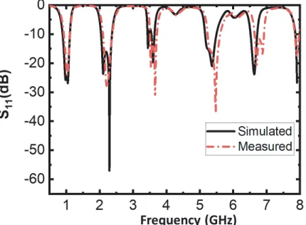
Figure 8. Simulated vs. measured S11 (dB) of the proposed quintuple band BPF.
parameters which can also control the bandwidth of the bands, e.g., the widths of the corresponding stub are also significant to control the bandwidth. We have chosen the optimized widths of the corresponding stubs to control the bandwidths. Furthermore, we claim that it should only be one of the several parameters that slightly change the bandwidth as can be seen from Figure 6.
The proposed filter is also measured, and its frequency response is provided. The simulated vs. measured S11 and S21 responses are shown in Figures 7 and 8, respectively. Good matching can be seen between the simulated and measured responses of the proposed filter. Figure 7 and Figure 8 both show that the proposed quintuple band bandpass filter is tuned to frequency bands, GSM-900, LTE2300, WiMAX (3.5 GHz), WLAN (5.4 GHz), and RFID (6.8 GHz). The operating mid frequencies of quintuple band bandpass filter are 0.96 GHz, 2.22 GHz, 3.58 GHz, 5.41 GHz, and 6.64 GHz with corresponding 3 dB FBW of 36.03%, 20.95%, 7.27%, 8.57%, and 3.37%. The measured insertion losses are 0.38 dB, 0.59 dB, 1.47 dB, 1.53 dB, and 2.4 dB at GSM-900, LTE2300, WiMAX, WLAN, and RFID frequency bands, respectively, and measured reflection coefficient is better than −20 dB at each passband. As can be seen from Figure 7, nine transmission zeros (Tz) are created which highly increase the skirt selectivity between the passbands. The prototype of the proposed filter is shown in Figure 9.
Figure 9. Prototype of quintuple band BPF.
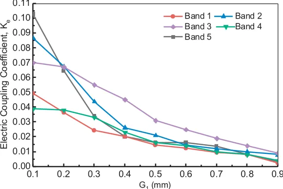
coupling is actually a function of the distance between the two resonators. This magnetic coupling is very difficult to exactly calculate in such a complicated structure, so it is optimized using EM simulation. However, we have calculated the electric coupling coefficient ‘Ke’ vs. ‘G1’ using the relation:
ke= f
2
h−fl2
f2
h+fl2
(27)
wherefl andfh represent the lower and higher frequencies of the two resonant frequency bands. Also,
the external quality factor, ‘Qe’, can be calculated from full wave simulated transmitted coefficients
given in [17] as:
Qe= ω0
Δω(3 dB) (28)
where ω0 accounts for the resonant frequency, and Δω(3 dB) is the 3 dB bandwidth of the resonator centered withω0.
The electric coupling coefficient of the proposed filter is dependent on parameter ‘G1’ and plotted in Figure 10. It is seen that as the distance ‘G1’ increases, the corresponding electric coupling also decreases as expected. However, it is observed that the distance ‘G1’ has a different influence on different passbands. The external quality factor of the proposed bandpass filter is also calculated from Equation (28), and it is plotted in Figure 11 with parameter ‘Wf’ taken from Figure 2.
0.1 0.2 0.3 0.4 0.5 0.6 0.7 0.8 0.9
0.00 0.01 0.02 0.03 0.04 0.05 0.06 0.07 0.08 0.09 0.10 0.11
E
le
c
tr
ic
C
o
u
p
li
n
g
C
o
e
ffi
c
ie
n
t,
Ke
G1 (mm)
Band 1 Band 2
Band 3 Band 4
Band 5
0.2 0.4 0.6 0.8 1.0 1.2 1.4 1.6 1.8 2.0 0
10 20 30 40 50 60 70 80 90
E
x
te
rn
a
l Q
u
al
it
y
F
a
c
tor
, Q
e
Wf (mm)
Band 1 Band 2
Band 3 Band 4
Band 5
Figure 11. External quality factor ‘Qe’ vs. parameter ‘Wf’ of the proposed Filter.
6. COMPARISON OF THE PROPOSED FILTER WITH RECENTLY PUBLISHED ONES IN THE LITERATURE
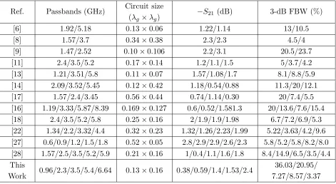
The proposed quintuple band bandpass filter is compared with recently proposed structures in the literature in Table 2. The proposed filter is advantageous in terms of circuit size, maximum passbands, 3-dB fractional bandwidth, and improved isolation. Moreover, five passbands within a single structure are also provided which is very appealing.
Table 2. Comparison of the proposed quintuple band bandpass filter with other state of the art.
Ref. Passbands (GHz) Circuit size (λg×λg)
−S21(dB) 3-dB FBW (%)
[6] 1.92/5.18 0.13×0.06 1.22/1.14 13/10.5
[8] 1.57/3.7 0.34×0.38 2.3/2.3 4.5/4
[9] 1.47/2.52 0.10×0.106 2.2/3.1 20.5/23.7
[11] 2.4/3.5/5.2 0.17×0.14 1.2/1.1/1.5 5/3.7/4.2 [13] 1.21/3.51/5.8 0.11×0.07 1.57/1.08/1.7 8.1/8.8/5.9 [14] 2.09/3.52/5.45 0.12×0.42 1.18/0.54/0.88 11.3/20/12.1 [17] 1.57/2.4/3.45 0.56×0.44 0.74/1.14/0.30 20/7.4/5.5 [16] 1.19/3.33/5.87/8.39 0.169×0.127 0.6/0.52/1.581.3 20/13.6/7.6/15.4 [18] 2.4/3.5/5.2/5.8 0.25×0.16 2/1.9/1.9/1.98 6.7/7.2/6.9/5.3 [22] 1.34/2.2/3.32/4.4 0.32×0.23 1.32/1.26/2.23/1.99 5.22/3.63/4.2/9.6 [27] 0.6/0.9/1.2/1.5/1.8 0.52×0.05 2.8/2.9/2.9/2.6/2.3 5.8/5.2/5.8/8.2/8.0 [28] 1.57/2.5/3.5/5.2/5.9 0.21×0.16 1/0.4/1.1/1.6/1.8 8.4/14.9/6.5/3.5/4.4 This
Work 0.96/2.3/3.5/5.4/6.64 0.13×0.16 0.38/0.59/1.4/1.53/2.4
7. CONCLUSIONS
A very compact quintuple band bandpass filter utilizing multimode stub loaded resonator (MSLR) is presented. The proposed SLR is analyzed, and the corresponding resonance frequencies are developed. The operating resonant frequencies of quintuple-band BPF are 0.96 GHz, 2.22 GHz, 3.58 GHz, 5.41 GHz, and 6.64 GHz which correspond to the center frequencies of GSM-900, LTE2300, WiMAX, WLAN, and RFID (6.8 GHz) bands. The proposed MSLR is analyzed, and the corresponding even and odd mode frequencies are developed. The inter-resonator coupling between different passbands of the proposed structure is also investigated and discussed. The proposed quintuple bandpass filter is also fabricated, and its measured response is correlated with the simulated ones. The proposed filter will pave the way in future wireless communication transceivers due to its small size and attractive performance.
REFERENCES
1. Li, J. L., J. X. Chen, J. P. Wang, W. Shao, Q. Xue, and L. J. Xue, “Miniaturised microstrip bandpass filter using stepped impedance ring resonators,” Electron. Lett., Vol. 40, No. 22, 1420– 1421, 2004.
2. Hsieh, L.-H. and K. Chang, “Compact lowpass filter using stepped impedance hairpin resonator,”
Electron. Lett., Vol. 37, No. 14, 899–900, 2001.
3. Ma, K. X., J. G. Ma, M. A. Do, and K. S. Yeo, “Compact two-order bandpass filter with three finite zero points,”Electron. Lett., Vol. 41, No. 15, 846–848, 2002.
4. Zhu, L., V. Devabhaktuni, C. Wang, and M. Yu, “A bandpass filter with adjustable bandwidth and predictable transmission zeros,” International Journal of RF and Microwave Computer-Aided Engineering: Co-sponsored by the Center for Advanced Manufacturing and Packaging of Microwave, Optical, and Digital Electronics (CAMPmode) at the University of Colorado at Boulder 20, No. 2, 148–157, 2010.
5. Hsieh, L.-H., G. L. Stolarczyk, and K. Chang, “Microstrip dual-band bandpass filters using parallel-connected open-loop ring resonators,”International Journal of RF and Microwave Computer-Aided Engineering: Co-sponsored by the Center for Advanced Manufacturing and Packaging of Microwave, Optical, and Digital Electronics (CAMPmode) at the University of Colorado at Boulder 18, No. 3, 219–224, 2008.
6. Xu, J. and J.-D. Zhang, “Compact dual-and triband bandpass filter using frequency selecting coupling structure loaded stepped-impedance resonator,” International Journal of RF and Microwave Computer-Aided Engineering, Vol. 25, No. 5, 427–435, 2015.
7. Xu, J., “Compact second-order dual-and quad-band bandpass filters using asymmetrical stub-loaded resonator and uniform-impedance resonator,” Microwave and Optical Technology Letters, Vol. 57, No. 4, 997–1003, 2015.
8. Deng, K., Z. Chen, G. Hu, and W. Feng, “Dual-band bandpass filters with multiple transmission zeros using λ/4 stepped-impedance resonators,” International Journal of RF and Microwave Computer-Aided Engineering, e21469.
9. Liu, H., P. Wen, S. Zhu, and B. Ren, “Independently controllable dual-band microstrip bandpass filter using quadruple-mode stub-loaded resonator,” International Journal of RF and Microwave Computer-Aided Engineering, Vol. 26, No. 7, 602–608, 2016.
10. Sun, S.-J., T. Su, K. Deng, B. Wu, and C.-H. Liang, “Compact microstrip dual-band bandpass filter using a novel stub-loaded quad-mode resonator,”IEEE Microwave and Wireless Components Letters, Vol. 23, No. 9, 465–467, 2013.
11. Doan, M. T., W. Q. Che, and W. J. Feng, “Tri-band bandpass filter using square ring short stub loaded resonators,” Electron. Lett., Vol. 48, No. 2, 106–107, 2012.
12. Hejazi, Z. M., “A fast design approach of compact microstrip multiband bandpass filters,”
13. Xu, J. and J.-D. Zhang, “Compact dual-and triband bandpass filter using frequency selecting coupling structure loaded stepped-impedance resonator,” International Journal of RF and Microwave Computer-Aided Engineering, Vol. 25, No. 5, 427–435, 2015.
14. Li, J., “Multi-mode resonators with quad-/penta-/sext-mode resonant characteristics and their applications to bandpass filters,” International Journal of RF and Microwave Computer-Aided Engineering, Vol. 27, No. 3, e21072, 2017.
15. Qiu, F., J. Huang, D. Lei, Z. Tang, and M. Yao, “Dual-band to tri-band to quad-band passband switchable bandpass filter,”Microwave and Optical Technology Letters, Vol. 59, No. 9, 2307–2311, 2017.
16. Xu, J., W. Wu, and C. Miao, “Compact microstrip dual-/tri-/quad-band bandpass filter using open stubs loaded shorted stepped-impedance resonator,”IEEE Transactions on Microwave Theory and Techniques, Vol. 61, No. 9, 3187–3199, 2013.
17. Rahman, M. U. and J.-D. Park, “A compact tri-band bandpass filter using two stub-loaded dual mode resonators,”Progress In Electromagnetics Research M, Vol. 64, 201–209, 2018.
18. Yan, T., X. H. Tang, and J. Wang, “A novel quad-band bandpass filter using short stub loaded E-shaped resonators,” IEEE Microw. Wirel. Compon. Lett., Vol. 25, 508–510, 2015.
19. Chen, F.-C. and Q.-X. Chu, “Design of quad-band bandpass filter using assembled resonators,”
Microwave and Optical Technology Letters, Vol. 53, No. 6, 1305–1308, 2011.
20. Weng, M.-H., C.-S. Ye, Y.-K. Su, and S.-W. Lan, “A new compact quad-band bandpass filter using quad-mode stub loaded resonator,” Microwave and Optical Technology Letters, Vol. 56, No. 7, 1630–1632, 2014.
21. Zhang, Z.-c., Q.-X. Chu, and F.-C. Chen, “Novel quad-band filter with high frequency ratio and controllable bandwidths using SLHSIRs and SLQSIRs,”Microwave and Optical Technology Letters, Vol. 56, No. 12, 2845–2848, 2014.
22. Gan, D., S. He, Z. Dai, and J. Wang, “A quad-band bandpass filter using split-ring based on T-shaped stub-loaded step-impedance resonators,”Microwave and Optical Technology Letters, Vol. 59, No. 8, 2098–2104, 2017.
23. Rahman, M., M. Naghshvarian Jahromi, S. S. Mirjavadi, and A. M. Hamouda, “Bandwidth enhancement and frequency scanning array antenna using novel UWB filter integration technique for OFDM UWB radar applications in wireless vital signs monitoring,” Sensors, Vol. 18, 3155, 2018.
24. Zheng, X., Y. Pan, and T. Jiang, “UWB bandpass filter with dual notched bands using T-shaped resonator and L-shaped defected microstrip structure,”Micromachines, Vol. 9, 280, 2018.
25. Rahman, M. U., D. S. Ko, and J. D. Park, “A compact tri-band bandpass filter utilizing double mode resonator with 6 transmission zeros,” Microwave and Optical Technology Letters, Vol. 60, No. 7, 1767–1771, 2018.
26. Moradi, B., R. Fern´andez-Garc´ıa, and I. Gil, “Meander microwave bandpass filter on a flexible textile substrate,”Electronics, Vol. 8, 11, 2019.
27. Chen, C.-F., “Design of a compact microstrip quint-band filter based on the tri-mode stub-loaded stepped-impedance resonators,”IEEE Microwave and Wireless Components Letters, Vol. 22, No. 7, 357–359, 2012.
28. Chen, L. and W. Feng, “Compact quad- and quint-band BPFs based on multimode stub loaded resonators,”Microw. Opt. Technol. Lett., Vol. 57, 2837–2841, 2015.