Aus der Poliklinik für Zahnärztliche Prothetik der
Ludwig-Maximilians-Universität München
Direktor: Prof. Dr. med. dent. Dr. h.c. Wolfgang Gernet
Einfluss der Testmethode auf den Verbund zwischen
CAD/CAM-Hochleistungspolymer und kunststoffbasierten
Befestigungsmaterialien nach unterschiedlichen
Vorbehandlungen
Dissertation
zum Erwerb des Doktorgrades der Zahnmedizin
an der Medizinischen Fakultät der
Ludwig-Maximilians-Universität zu München
vorgelegt von
Simona Gilbert
Mit Genehmigung der Medizinischen Fakultät
der Universität München
Berichterstatter: Prof. Dr. med. dent. Daniel Edelhoff
Mitberichterstatter: Priv.-Doz. Dr. rer. nat. Dr. med. Jürgen Durner
Mitbetreuung durch die promovierte Mitarbeiterin:
Dr. rer. biol. hum. Dipl. Ing (FH) Bogna Stawarczyk, MSc
Dekan: Prof. Dr. med. Dr. h.c. Maximilian Reiser, FACR,
FRCR
Eidesstattliche Versicherung
Gilbert, Simona AndreeaIch erkläre hiermit an Eides statt, dass ich die vorliegende Dissertation mit dem Thema:
Einfluss der Testmethode auf den Verbund zwischen
CAD/CAM-Hochleistungspolymer und kunststoffbasierten Befestigungsmaterialien nach unterschiedlichen Vorbehandlungen
selbständig verfasst, mich außer der angegebenen keiner weiteren Hilfsmittel bedient und alle Erkenntnisse, die aus dem Schrifttum ganz oder annähernd übernommen sind, als solche kenntlich gemacht und nach ihrer Herkunft unter Bezeichnung der Fundstelle einzeln nachgewiesen habe.
Ich erkläre des Weiteren, dass die hier vorgelegte Dissertation nicht in gleicher oder in ähnlicher Form bei einer anderen Stelle zur Erlangung eines akademischen Grades eingereicht wurde.
Inhaltsverzeichnis
1 Zusammenfassung ... 6
2 Summary ... 8
3 Introduction ... 10
4 Materials and Methods ... 13
4.1 Shear bond strength test method (SBS) ... 16
4.2 Tensile bond strength test method (TBS) ... 17
4.3 Fracture type analyses after SBS or TBS measurements ... 19
4.4 Work of adhesion (WA) test method ... 20
4.5 Statistical analysis ... 23
5 Results ... 24
5.1 SBS test method results ... 24
5.2 TBS test method results ... 26
5.3 Fracture types ... 27
5.4 Surface characteristics results, such as SFE, Surface polarity, WA, IFT and SC ... 29
5.5 Correlation between test methods ... 32
6 Discussion ... 34
7 Schlussfolgerung ... 40
8 References ... 41
9 Abbildungsverzeichnis ... 46
10 Tabellenverzeichnis ... 47
Zusammenfassung
6
1 Zusammenfassung
Ziel dieser Untersuchung war es, den Verbund zwischen einem CAD/CAM-Hochleistungskunststoff nach verschiedenen Vorbehandlungen sowie drei unterschiedlich zusammengesetzten Befestigungsmaterialien zu testen. Dazu wurden die Versuche in drei unterschiedlichen Testaufbauten durchgeführt und die Resultate anschließend miteinander verglichen.
7
gewonnenen Daten wurden mit Mann-Whitney-U-, Kruskal-Wallis-H-, Chi2-und Spearman-Roh-Tests ausgewertet.
Innerhalb von SBS- und TBS-Tests zeigten die CG, die Gruppen, die mit CP vorbehandelt wurden (unabhängig vom Befestigungsmaterial) und VP, welches mit Clearfil SA Cement vorbehandelt wurde, keinen Verbund. Allerdings war bei CG in Kombination mit RelyX ARC eine TBS von 5,6 ± 1,3 MPa messbar. Im Allgemeinen wurden die höchsten Verbundfestigkeiten für Gruppen, die mit VL behandelt wurden beobachtet. Die CG Gruppe, sowie Gruppen, die mit VL vorbehandelt wurden, zeigten eine niedrigere WA, als die mit VP oder CP behandelten Gruppen.
Insgesamt waren die gemessenen TBS-Werte höher als die SBS-Werte. Im Allgemeinen zeigten SBS und TBS ähnliche Trends innerhalb der geprüften Gruppen. Dagegen waren die WA Ergebnisse, nicht vergleichbar mit den im SBS/TBS Test erzielten Ergebnissen.
Summary
8
2 Summary
The aim of this in-vitro study was to assess the bonding properties between CAD/CAM-resin and three resin composite cements combined with different bonding agents, using three test methods.
Four-hundred-twenty CAD/CAM-resin substrates were fabricated and divided into three test method groups: n=180 for shear bond strength (SBS), n=180 for tensile bond strength (TBS), and n=60 for determination of work of adhesion (WA). The substrates were pretreated as followed (n=15 per test method/resin composite cement/pretreatment): i) VP connect (VP), ii) visio.link (VL), iii) Clearfil Ceramic Primer (CP), and iv) no pretreatment (CG) acted as control group, and luted with RelyX ARC, Variolink II, or Clearfil SA Cement. SBS and TBS were measured after 24h H2O/37°C + 5,000 thermal-cycles (5°C/55°C) and failure types were assessed. WA was determined for pretreated CAD/CAM-resin and non-polymerized resin composite cements. Data were analyzed with Mann-Whitney-U-, Kruskal-Wallis-H-, Chi2- and Spearman-Roh-tests.
9
Introduction
10
3 Introduction
The industrially standardized CAD/CAM-processing of polymers leads to significantly higher mechanical properties in comparison to manually polymerized resins.1,11,27,30 Due to the high pressure and temperature during the fabrication of the blanks, there is a reduced risk of porosities and inhomogeneities for CAD/CAM manufactured restorations.20,21,31 Not only improved mechanical properties, including wear resistance19,30, but also advanced optical behavior, such as inferior discoloration31, are among the advantages of CAD/CAM-resin materials, when compared to conventional polymerized resin. In addition to that the occlusal wear of resin materials is similar to that of enamel and therefore gentle to the natural antagonists.33
The first generation of CAD/CAM-resins was usually filled or unfilled polymethylmethacrylate (PMMA) with modified polymer networks.32 However, the higher deformation caused by the low elastic modulus (2 GPa) of pure PMMA-resins was a limitation of these materials. Further developments lead to new and improved classes of resin materials, which can be optimized through the assembly of several components, such as dimethacrylate, with different organic and anorganic filler particles, and tend to be closer to the characteristics of human teeth.6 The generation of this new CAD/CAM-resins came from the filling composites in preventive dentistry.
11
reproductability for the definite restoration are important advantages of the new CAD/CAM-methods.12,13 Nevertheless, there is no certain recommendation available concerning the duration of the pretreatment time.8 In general, the industrially standardized polymerization of CAD/CAM-resins results in a higher degree of conversion with less residual monomer in the material and made the bonding to resin composite cement difficult.26 However, creating durable bond between the restoration and the tooth is crucial for long-term reliability and, therefore, its success.
There are several test methods that can be used to describe the bond strength of bonding agents, including the well-known shear bond tests and tensile bond strength tests, or newer and more accurate test methods, such as micro-shear and micro-tensile tests.2 Both micro-methods gave higher bond strength values as a result of the smaller bonding area, but at the same time, they are very technique-sensitive and elaborate in comparison to the macro test methods.10,14 However, macro test methods are more commonly used.10,14 Therefore, the macro bond strength tests were applied due to their direct and quick results, as well as their ease of handling.14
Introduction
12
Other important facts for the achievement of a durable bond are the chemical, physical and mechanical adhesion properties of the substrate surface as well as that of the resin cement. Generally, the mechanical adherence is the most powerful one, but resin – resin interfaces require also chemical bonding which can be improved by application of adhesive systems and the roughening of the surface.18,24 These improvements of bond strength are shown to increase the wettability of the resin substrate surfaces and can be quantified with contact angle measurements.18,23 This is the most common test method which gives important information about the work of adhesion (WA), the interfacial tension (IFT) and the spreading coefficient (SC) of the different materials.18
13
4 Materials and Methods
This study tested the bond strength properties to XHIPC-CAD/CAM-resin (Xplus3, Echzell, Germany) after following pretreatment methods using different bonding agents: VP connect (Merz Dental, Lütjenburg, Germany), visio.link (Bredent, Senden, Germany), or Clearfil Ceramic Primer (Kuraray Med., Sakazu, Japan). They were bonded with two conventional resin cements, RelyX ARC (3M ESPE, Seefeld, Germany) and Variolink II (Ivoclar Vivadent, Schaan, Liechtenstein), and a self-adhesive resin cement Clearfil SA Cement (Kuraray, Tokyo, Japan). A control group (CG) without a bonding agent was also used in combination with all cements. Bond strength of all combinations was examined with shear bond strength method (SBS), tensile bond strength method (TBS) and work of adhesion (WA), which was theoretically calculated.
Materials and Methods
14
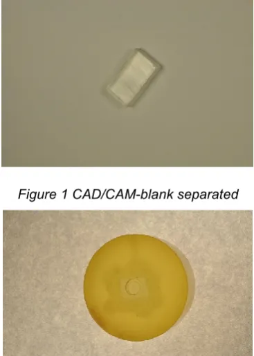
Figure 1 CAD/CAM-blank separated
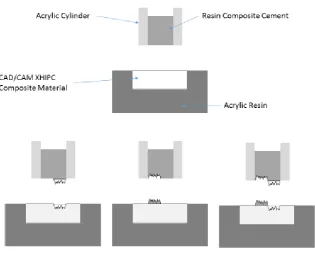
Figure 2 CAD/CAM-blank embedded in acrylic resin
15
Table 1 Summary of materials used in the present study, their manufacturer with LOT number, and their composition
Materials Manufacture Lot No. Compositions
CAD/CAM-blank
XHIPC- CAD/CAM-blank
Xplus3, Echzell, Germany
321120 50-80%: PMMA,
10-20%: UDMA,
BDDMA,
mutli-methacrylate, 5-15% filler Conditioning
method
VP connect Merz Dental, Lütjenburg,
Germany
22912 MMA
visio.link Bredent, Senden, Germany
114784 MMA, dimethacrylate PETIA, photoinitiators Clearfil
Ceramic Primer
Kuraray Med., Sakazu,
Okayama, Japan
3-Methacryloxypropyl trimethoxy silane, MDP, ethanol
Resin cement
Clearfil SA Cement
Kuraray Med., Sakazu,
Okayama, Japan
058AAA PASTE A: MDP,
Bis-GMA, TEGDMA,
dimethylacrylate, Ba-Al fluorosilicate glass, SiO2, benzoylperoxide, initiators
PASTE B: Bis-GMA, dimethacrylate, Ba-Al fluorosilicate glass, SiO2, pigments
RelyX ARC 3M ESPE,
Seefeld, Germany Bis-GMA, TEGDMA amine, photoinitiator system (CQ), Benzoyl
peroxide and
stabilizers Variolink II Ivoclar Vivadent,
Schaan, Liechtenstein Base: R35481 Catalyst: P84939
Bis-GMA, TEGDMA,
UDMA,
benzoylperoxide,
inorganic fillers, ytterbium trifluoride, Ba-Al fluorosilicate glass, spheroid mixed
oxide, initiator,
stabilizers, pigments TEGDMA: Triethylenglycoldimethacrylate,
MMA: Methylmethacrylate,
BDDMA: 1.4 Buthandioldimethacrylat; Bis-GMA: Bisphenol A - glycidyl methacrylate, UDMA: Urethane dimethacrylate,
MDP: 10-Methacryloyloxydecyl-dihydrogen phosphate, PETIA:Pentaerythritoltriacrylate
Materials and Methods
16
Following pretreatment were performed:
1. VP connect (VP) was applied as thin layer and air-dried for 180 sec. 2. visio.link (VL) was applied as thin layer and light cured for 90 sec. with a
manufacturer recommended light unit (bre.Lux Power Unit, Bredent, Senden, Germany).
3. Clearfil Ceramic Primer (CP) was applied as thin layer and allowed to vaporize completely.
4. No further pretreatment of CAD/CAM-resin served as the control group (CG).
Each pretreatment group was subdivided according to the above listed resin composite cements (n=15 per group). Polymerization of resin composite cements (SBS and TBS test) was performed on two sides of the acrylic cylinder for 20 sec. each for 40 sec. in total (Elipar S 10, 3M ESPE, Seefeld, Germany). Immediately before the polymerization, the intensity of the LED light-curing unit was measured using an analyzing device (Marc V3, BlueLight analysis Inc., Halifax, NS, USA). The LED lamp had a light intensity of 1200 mW/cm2. After the cementation, all specimens were stored in distilled water in an incubator at 37 ºC for 24 h (HERA cell 150 Thermo scientific, Heraeus, Hanau, Germany) and then artificially aged for 5,000 cycles of thermal aging (Thermocycler THE 1100, SD Mechatronik, Feldkirchen-Westerham, Germany) between 5 °C and 55 °C with a dwell time of 20 sec. Before the SBS and TBS tests, specimens were released in distilled water for 1 h at room temperature (23 °C).
4.1 Shear bond strength test method (SBS)
17
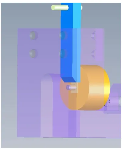
centrally placed on the CAD/CAM material surface. To obtain a standardized and homogeneous cemented layer with a height of 0.5 mm, a screw with an outer diameter of 2.8 mm was driven into the core of the acrylic cylinder and loaded with 1 N. Excess resin cement could exit through the screw thread and was cleaned carefully. Polymerization and artificial aging was performed as described. For testing, the specimens were fixed in a Universal Testing Machine (Zwick 1445, Zwick, Ulm, Germany) with the CAD/CAM-resin surface parallel to the loading direction and the acrylic cylinder in horizontal direction and vertically loaded until fracture (1 mm/min) (Fig. 3).5,28
Figure 3 Design of SBS Testing device
4.2 Tensile bond strength test method (TBS)
Materials and Methods
18
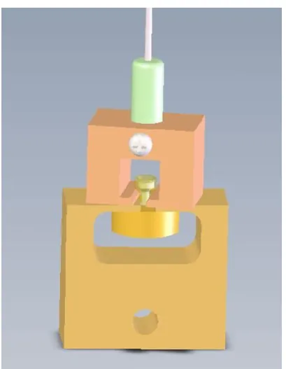
cement was carefully removed. Polymerization and artificially aging was performed analogue to the shear bond strength method. For testing, the specimens were fixed in special holding device, ensuring an axial moment-free force application in the Universal Testing Machine (Zwick 1445). The acrylic cylinder was held by a collet while an alignment jig that allowed self-alignment of the specimens. The device was installed to the load cell of the Testing Machine and pulled apart by an upper chain, guaranteeing a self-centring of the whole system. The TBS was measured by axially pulling with a constant crosshead speed of 5 mm/min until the specimens disconnected (Fig. 4).17,29
Both, SBS and TBS, were calculated according to the following equation. σ [N/mm2] = F/A (where σ: shear or tensile bond strength, F: load at fracture [N], and A: adhesive area [mm²]).
19
4.3 Fracture type analyses after SBS or TBS measurements
After obtaining the SBS and TBS measurements, the failure type analyses were performed. The failure types were analyzed for adhesive, cohesive, and mixed fracture types (Fig. 5). The adhesive type was defined as fracture in the bonding area (interface), whereas the cohesive fracture was distinguished as fractures of the tested CAD/CAM-resin or otherwise of the cement. The mixed failure was used to describe more types of fractures (cohesive and adhesive) in one specimen. All failure types were evaluated by two calibrated examiners, who were unaware of the group allocation and treatment, under an optical microscope (Axioskop 2 MAT, Karl Zeiss Mikroskopie, Göttingen, Germany).
Figure 5 Failure types analyses: above: adhesive failure; left down: cohesive failure among substrate, center down: cohesive failure among resin composite cement; and right down: mixed failure left to
Materials and Methods
20
4.4 Work of adhesion (WA) test method
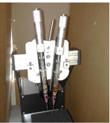
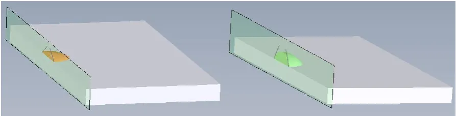
To evaluate the theoretical work of adhesion, the surface of the pretreated CAD/CAM-resin, and the surface of all three non-polymerized resin composite cements (n=15 per group) were analyzed. The sessile drop technique was used to perform the contact angle measurement. The measurements were accomplished in a contact angle meter (EasyDrop, Krüss, Hamburg, Germany) using two microsyringes, one filled with distilled water and the other with diiodomethane (99%; Cat: 15.842-9, Sigma-Aldrich, Steinheim, Germany, LOT No: S65447-448) as polar and disperse fluids at room temperature (23 °C) (Fig. 6). An attached digital camera registered the applied fluid drops with a known volume (10 µl water and 5 µl diiodomethane) after exactly 1 sec. using of a special computer program (DSA4, Krüss), the height and diameter of each drop was measured and, therefore, the static contact angle was determined using two different computation methods depending on the angle of the fluid used (Fig. 7- Fig. 8). For flat angles the Circle Method was chosen. The contact angle constructed using distilled water was determined with the Tangent 1 Method. Each specimen was provided with three drops of distilled water and three drops of diiodomethane and the mean contact angle for each liquid was calculated.
21
Based on the formula of OWENS, WENDT, RABEL and KAELBLE the computer program determined the surface free energies (SFE) of the CAD/CAM-resin in combination with all pretreatments as well as those of the CAD/CAM-resin cements.15,22 All SFE results were divided into their polar and dispers shares.
( )
( √ ) √ √
√
SFELP: Surface free energy of the liquid, polar component SFESP: Surface free energy of the solid, polar component SFELD: Surface free energy of the liquid, dispersive component SFESD: Surface free energy of the solid, dispersive component θ: contact angle
Subsequently, the WA between the CAD/CAM-resin after pre-treatment (BS) and the non-polymerized resin composite (RC) cement was calculated using the sum of the polar (SFE (P)) and disperse (SFE (D)) shares of the surface free energies (SFE). These results were put into a formula with the following connection to determine the work of adhesion
√ √
Materials and Methods
22
√ √
BS: Surface free energy of the bonding system, BSP: polar component
RC: Surface free energy of the resin composite cement, � RCP: polar component
BS: Surface free energy of the bonding system, BSD: dispersive component
RC: Surface free energy of the resin composite cement, RCD: dispersive component
Figure 7 Computer program for determination of SFE
23
4.5 Statistical analysis
Results
24
5 Results
Kolmogorov-Smirnov and Shapiro tests indicated that SBS, TBS, and WA groups were not normally distributed. Hence, non-parametric statistical analyzes were performed.
5.1 SBS test method results
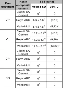
CGs and groups pretreated using CP, regardless of resin cements used, as well as VP combined with Clearfil SA Cement, showed no bond to the CAD/CAM-resin (Table 2).
Table 2 Mean values, standard deviation and 95% confidence intervals (CI) for SBS
Mean ± SD 95% CI
Clearfil SA
Cement 0A 0
RelyX ARC 9.9 ± 6.8C (5;15)
Variolink II 8.4 ± 4.6B (5;12)*
Clearfil SA
Cement 13.2 ± 5.4B (9;17)
RelyX ARC 13.2 ± 4.1C (9;16)*
Variolink II 17.0 ± 3.8C (13;20)* Clearfil SA
Cement 0A 0
RelyX ARC 0A 0
Variolink II 0A 0
Clearfil SA
Cement 0A 0
RelyX ARC 0A 0
Variolink II 0A 0
CP CG SBS (MPa) Pre-treatment Resin composite cement VP VL
* not normal distributed
25
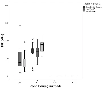
Among all resin composite cements, the highest bond strength (p<0.001) was observed for groups pretreated with VL (13.2–17.0 MPa). No differences were found between groups bonded with RelyX ARC combined with VP (9.9 6.8 MPa) and VL (13.2 4.1 MPa). Within the resin composite cement Variolink II, specimens pretreated using VL (17.0 3.8 MPa) had higher SBS as compared to ones pretreated using VP (8.4 4.6 MPa) (Fig. 9).
Results
26
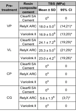
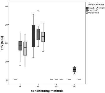
5.2 TBS test method results
Except for CG cemented with RelyX ARC, which had TBS values of 5.6 1.3 MPa, CGs cemented with Clearfil SA Cement and Variolink II, all groups pretreated with CP, and VP combined with Clearfil SA Cement showed no bond (Table 3). Analogous to the SBS results, RelyX ARC and Variolink II pretreatment using VL (23.0–25.3 MPa) showed a higher TBS (p<0.001) when compared to groups pretreated with VP (16.9–18.0 MPa) (Fig. 10).
Table 3 Mean values, standard deviation and 95% confidence intervals (CI) for TBS
Mean ± SD 95% CI
Clearfil SA
Cement 0A 0 RelyX ARC 18.0 ± 5.0C (14;21)*
Variolink II 16.9 ± 5.0B (13;20)*
Clearfil SA
Cement 24.1 ± 7.2B (19;29)* RelyX ARC 25.3 ± 5.0C (21;29)*
Variolink II 23.0 ± 4.2C (19;26)*
Clearfil SA
Cement 0A 0 RelyX ARC 0A 0 Variolink II 0A 0 Clearfil SA
Cement 0A 0 RelyX ARC 5.6 ± 1.3B (3;7)*
Variolink II 0A 0 CP CG TBS (MPa) Pre-treatment Resin composite cement VP VL
* not normal distributed
27
Figure 10 Box plot for TBS results
5.3 Fracture types
Results
28
Table 4 Relative failure type frequencies with 95% CIs for each failure type after SBS and TBS measurements (%) Resin composite cement Pre-treatment Adhesive Cohesive (resin composite cement) Cohesive (XHIPC) Mixed SBS
VP 100 (77;100) 0 (0;23) 0 (0;23) 0 (0;23)
VL 100 (77;100) 0 (0;23) 0 (0;23) 0 (0;23)
CP 100 (77;100) 0 (0;23) 0 (0;23) 0 (0;23)
CG 100 (77;100) 0 (0;23) 0 (0;23) 0 (0;23)
Chi²-test
VP 20 (3;49) 13 (1;42) 53 (25;80) 13 (1;42)
VL 73 (43;93) 7 (0;33) 20 (3;49) 0 (0;23)
CP 100 (77;100) 0 (0;23) 0 (0;23) 0 (0;23)
CG 60 (31;85) 13 (1;42) 20 (3;49) 7 (0;33)
Chi²-test
VP 33 (10;63) 67 (37;89) 0 (0;23) 0 (0;23)
VL 40 (15;69) 47 (20;75) 0 (0;23) 13 (1;42)
CP 100 (77;100) 0 (0;23) 0 (0;23) 0 (0;23)
CG 100 (77;100) 0 (0;23) 0 (0;23) 0 (0;23)
Chi²-test TBS
VP 100 (77;100) 0 (0;23) 0 (0;23) 0 (0;23)
VL 33 (10;63) 20 (3;49) 0 (0;23) 47 (20;75)
CP 100 (77;100) 0 (0;23) 0 (0;23) 0 (0;23)
CG 100 (77;100) 0 (0;23) 0 (0;23) 0 (0;23)
Chi²-test
VP 80 (50;97) 7 (0;33) 0 (0;23) 13 (1;42)
VL 60 (31;85) 33 (10;63) 0 (0;23) 7 (0;33)
CP 100 (77;100) 0 (0;23) 0 (0;23) 0 (0;23)
CG 100 (77;100) 0 (0;23) 0 (0;23) 0 (0;23)
Chi²-test
VP 87 (58;99) 13 (1;42) 0 (0;23) 0 (0;23)
VL 93 (67;100) 0 (0;23) 0 (0;23) 7 (0;33)
CP 100 (77;100) 0 (0;23) 0 (0;23) 0 (0;23)
CG 100 (77;100) 0 (0;23) 0 (0;23) 0 (0;23)
Chi²-test Clearfil SA
-Rely X ARC
p=0.006
Variolink II
p=0.001
Clearfil SA
p<0.001
Rely X ARC
p=0.010
Variolink II
29
5.4 Surface characteristics results, such as SFE, Surface polarity,
WA, IFT and SC
The results of SFE and Surface polarity are depicted in Table 5.
Table 5 Mean values, standard deviation and 95% confidence intervals (CI) for SFE with disperse and polar components plus percentage stage of surface polarity for CAD/CAM-resin after pretreatment and resin composite cement separately
Mean Mean Mean Mean
± SD ± SD ± SD ± SD
64.4 48.8 15.6 24.3
± 0.7c ± 0.3c ± 0.6b ± 0.7b
45.8 43.1 2.7 5.8
± 0.6a ± 0.4a ± 0.4a ± 0.8a
64.9 48.5 16.3 25.1
± 2.4c ± 0.6c ± 2.3b ± 2.5b
48.1 46.0 2.1 4.3
± 3.0b ± 2.0b ± 2.5a ± 4.7a
55.1 43.8 11.3 20.4
± 2.0c ± 0.6a ± 2.1c ± 2.9c
49.9 44.2 5.3 10.7
± 1.7b ± 0.4a ± 1.1b ± 2.1b
47.4 46.3 1.1 2.3
± 0.8a ± 0.6b ± 0.5a ± 1.1a
(9;13) Variolink II (46;49) (45;48) (0;2) (1;4) RelyX ARC (48;52) (43;45) (4;7)
Resin Composite Cement
Clearfil SA
Cement (53;57) (43;45) (9;13) (18;23) (23;28)
CG (46;51) (44;48) (0;5)* (1;8)*
CP (63;67) (47;50) (14;19)*
VL (44;47) (42;44) (2;4) (4;7)
95% CI
Pretreatment
VP (63;66) (48;50) (14;17)
SFE (mJ/m2) SFEd (mJ/m2) SFEp (mJ/m2) Surface polarity (%)
95% CI 95% CI 95% CI
(23;26)
* not normal distributed
Results
30
Descriptive statistics are summarized in Table 6.
Table 6 Mean values, standard deviation and 95% confidence intervals (CI) for WA, IFT and SC
Mean ± SD 95% CI Mean ± SD 95% CI Mean ± SD 95% CI
Clearfil SA
Cement 119.0 ± 2.3c,B (117;121) 0.6 ± 0.4a,A (0;2) 8.8 ± 1.8a,B (7;11) RelyX ARC 111.1 ± 1.8b,B (109;113) 3.3 ± 1.7b,B (1;5)* 11.3 ± 2.9b,B (9;14)*
Variolink II 103.2 ± 2.0a,B (101;105) 8.6 ± 1.3c,B (7;10) 8.4 ± 1.2a,C (7;10)
Clearfil SA
Cement 97.9 ± 1.6c,A (96;100) 3.0 ± 1.0b,B (1;5) -12.3 ± 2.7a,A (-15;-10) RelyX ARC 94.8 ± 0.8b,A (93;96) 0.9 ± 1.3a,A (0;3)* -4.9 ± 2.9b,A (-8;-2)
Variolink II 92.7 ± 1.2a,A (91;94) 0.5 ± 0.4a,A (0;2) -2.1 ± 0.7c,A (-4;-1)
Clearfil SA
Cement 119.4 ± 4.0c,B (116;123)* 0.6 ± 0.3a,A (0;2) 9.1 ± 1.7a,B (7;11)* RelyX ARC 111.1 ± 2.1b,B (109;113) 3.6 ± 1.9b,B (2;6) 11.4 ± 3.3b,B (9;14)*
Variolink II 103.2 ± 2.4a,B (101;106)* 9.1 ± 1.6c,B (7;11) 8.3 ± 1.6a,C (7;10)
Clearfil SA
Cement 98.0 ± 5.8a,A (94;102) 5.2 ± 2.9c,C (3;8) -12.2 ± 5.5a,A (-16;-8) RelyX ARC 95.4 ± 3.6a,A (92;98) 2.6 ± 2.2b,AB (0;5) -4.3 ± 5.4b,A (-8;0)
Variolink II 95.0 ± 2.5a,A (93;97) 0.6 ± 0.7a,A (0;2)* 0.1 ± 2.7c,B (-2;3)
VL CP CG Pre-treatment Resin composite cement
WA (mN/m) IFT (mN/m) SC (mN/m)
VP
* not normal distributed
a,b,c: significant differences between resin composite cements within single pre-treatment group A,B,C: significant differences between pre-treatments within one resin composite cement
31
Variolink II. For control groups without pretreatment no differences were found for WA results between resin composite cements used, while CG combined with Clearfil SA Cement showed highest IFT results and lowest SC values. Opposed to this CG with Variolink II resulted in lowest IFT values and highest SC results.
Within the resin composite cements Clearfil SA Cement showed the highest SFE value, followed by RelyX ARC and Variolink II resulting in lowest values for SFE and percentage stage of surface polarity. In general for all composite resin cements higher WA and SC values were observed in combination with VP and CP than with VL and CG. Within Clearfil SA Cement highest IFT values were observed for CG. Within RelyX ARC and Variolink II the groups VP and CP showed higher IFT values compared to VL and GC. WA results are shown in Figure 11.
Results
32
5.5 Correlation between test methods
TBS values for Clearfil SA Cement combined with VL, RelyX ARC combined with VP, and VL, CG, and Variolink II combined with VL and VP were significantly higher than those examined using the SBS test method (p<0.001). Specifically, RelyX ARC without additional pretreatment showed no bond with SBS, while TBS values of 5.6 1.3 MPa were observed. Between TBS and SBS a positive correlation (r2=0.259, p<0.001) was observed.
33
Table 7 Non-parametric correlation between single test methods
Values for:
Test SFE SFEd SFEp
Surface polarity
in %
r=-0.321 r=-0.471 r=-0.146 r=-0.139 p<0.001 p<0.001 p=0.051 p=0.062 r=-0.383 r=-0.487 r=-0.258 r=-0.256 p<0.001 p<0.001 p=0.001 p=0.001
Values for:
Test SFE SFEd SFEp
Surface polarity
in %
r=-0.184 r=0.139 r=-0.194 r=-0.195 p=0.013 p=0.063 p=0.009 p=0.009 r=-0.155 r=0.066 r=-0.153 r=-0.152 p=0.040 p=0.384 p=0.043 p=0.043
Values for:
Test WA IFT SC
r=-0.342 r=-0.033 r=-0.212 p<0.001 p=0.656 p=0.004 r=-0.420 r=-0.044 r=-0.297
p<0.001 p=0.561 p<0.001
TBS
SBS
TBS
CAD/CAM resin after pretreatment together with resin composite cement
CAD/CAM resin after pretreatment
Resin composite cement SBS
TBS
Discussion
34
6 Discussion
This in-vitro study showed that different bonding agents influenced the adhesion between CAD/CAM-resin and resin composite cements, regardless of the test method used. Pretreatment using VL and VP (except when used in combination with Clearfil SA Cement) significantly improved the SBS and TBS compared to unpretreated surfaces or surfaces pretreated with MDP-based Clearfil Ceramic Primer. The bonding agents VL and VP contain MMA monomer. Consequently, it can be proposed that the tested CAD/CAM-resin was dissolved at its surface by application of VL and VP and the free carbon double bindings (C-C) polymerized with the carbon compounds of the bonding agent combined with the resin composite cement. VL showed the highest results, and this leads to the suggestion that the component PETIA has an additionally high solvent capacity. The supplementary polymerization process, after application of the bonding layer, consequently creates a strong connection between the XHIPC material and the MMA of the bonding agent that can be described as anchoring. In contrast, the adhesion with industrially polymerized resin after pretreatment with MDP monomers cannot be created. Therefore, the hypothesis that the use of bonding agent has an impact on bond strength, is validated.
35
The CAD/CAM-resin was bonded with two conventional resin cements (RelyX ARC and Variolink II) and one self-adhesive cement (Clearfil SA Cement). The main difference between the SBS and TBS values can be described by the configuration of the two conventional resin cements. Both contain Bis-GMA and TEGDMA with filler particles, and Variolink II also contains UDMA. The self–adhesive Clearfil SA Cement is based on 10-methacryloyloxydecyl-dihydrogenate (MDP). For VP connect, the CAD/CAM-resin showed no sufficient bond with Clearfil SA Cement, but it showed high values when used in combination with RelyX ARC cement (SBS: 9.9 MPa, TBS: 18.0 MPa) and Variolink II (SBS: 8.4 MPa, TBS: 16.9 MPa). Nevertheless, this study shows that higher bonding values can be achieved with conventional resin cements. This fact is also confirmed by other studies using both types of resin cements5,17 and can be explained by the chemical structure of the PMMA-based CAD/CAM-material, which consists of UDMA and filler particles. The highest bonding properties (SBS and TBS) were observed in groups pretreated with visio.link. Visio.link contains PETIA as solution, MMA monomers, and dimethacrylates. In contrast, VP connect contains only MMA and assumedly swell the surface more ineffectively as in combination with PETIA. Therefore, the measured SBS and TBS gave lower values when compared to specimens pretreated with visio.link.
Discussion
36
In order to simulate the clinical situation, artificial/accelerated aging by water storage and thermal cycling were used, since they are proven to induce a reduction of bond strength.25 Conversely, other studies showed an increase of bond strength after aging, claiming that it supports the post–polymerization process.5 Nevertheless, long-term validations of in-vitro tests do not necessarily correspond to the clinical results. Therefore, prolonged artificial aging by 6 months, instead of 24 h, water treatment should be performed.38 Thermal cycling is used to imitate the changing temperatures in the oral environment. The dwell time is important in order to avoid excessively fast thermal changes that can lead to an early debonding. Aging procedures were executed to imitate the corresponding clinical deterioration of 4 to 5 months in the oral medium, because this can affect the bond strength.34 Water uptake was shown to be higher in cements containing only TEGDMA, such as RelyX ARC. In contrast, Variolink II, which contains a mixture of TEGDMA and UDMA, has superior mechanical properties due to the presence of many crosslinks.35 In general; RelyX ARC with visio.link presented higher TBS values (25.3 MPa) than Variolink II with visio.link (23.0 MPa) after artificial aging.
37
Many studies discuss the validity and evidence of these different macro bond strength test methods and their relevance to the clinical situation, as well as the variation in the conclusions between these special tests.14,16 These investigations have differences, such as the dimension of specimens, type of testing jig, settings of testing machines, and stress distribution at the bonding interface. This makes it difficult to compare the results and thus it is debatable if there is still a lack of standardization.10,14,16 Within bond strength tests the applied force is divided by the bonding area in order to obtain the bond strength in MPa (N/mm²).36 The TBS test method applies the force vertically and, thus, pulls the junction apart. It was observed that more adhesive failures occur using this test method and, therefore, estimates the clinically more realistic situation.9,14 Kelly et al. mentioned that the tensile stresses for the TBS test method are even higher than for SBS tests due to the more unequal distribution at the exterior interface.16 This study used the same substrate geometry, acrylic cylinders with same cross-sections, and, therefore, an equal bond area, but different crosshead speed for SBS (1 mm/min) and TBS (5 mm/min). The study showed also higher TBS values than those of SBS. However, the measured values showed similar tendencies in the group ranging and can be compared. As the validation of this investigation proved, the SBS and TBS test methods can be recommended as easy and reliable screening methods for the testing of resin materials.
Discussion
38
failures for SBS and TBS, so it may be that the method of examination has to be seen as user-dependent despite all attempts of standardization.
The measurement of the work of adhesion gives important information about a materials´ surface and its characteristics and is shown to be an important factor for the adhesion performance of the tested materials.3,7 In the present study, all resin cements were measured in an uncured form with two different liquids. The CAD/CAM-blank was pretreated and polymerized before the determination of contact angles under atmospheric pressure. The tested CAD/CAM-resin surface was plane, so the contact angle measurement could be evaluated directly with the sessile drop technique using the Owens and Wendt, Rable and Kaeble formula.15,22 In this study, the groups pretreated with CP or VP, for instance, have almost similar WA results. Clearfil SA Cement has the highest WA (VP: 119.0 N/m, CP: 119.4 N/m) followed by Rely X ARC (VP 111.1 N/m; CP 111.1 N/m) and Variolink II (VP: 103.2 N/m, CP: 103.2 N/m). VL has the lowest WA results (92.7–97.9 N/m) independent of the resin cement used. However, the calculated WA values showed other tendencies in the SBS and TBS group ranging and cannot be compared. Additionally to the single parameter WA further surface characteristics are necessary to understand the process of bonding properties. This shows, that every single surface characteristic has to be observed in order to avoid false statements. However, these findings are important as destructive tests of bond strength (SBS, TBS) were commonly used to measure adhesion energy without taking into consideration the in measureable plastic deformation at the interface.24
39
the different pre-treatments with adhesives in an uncured form, in order to find a relation to bonding characteristics of polymerized and unpolymerized adhesives.4 Moreover, surface roughness could increase the surface area involving a lower contact angle, and can also evoke complete wetting of the surface. Surface roughness increases fracture energy and stress distribution at the interface, when destructive forces are applied.23,24 Though many authors discussed this topic using different equations and unities, it is a new method for dental materials, and there are still few reference values, so any comparison is difficult.
Schlussfolgerung
40
7 Schlussfolgerung
Anhand der in dieser Untersuchung erzielten Ergebnisse, kann behauptet
werden, dass für eine adhäsive Befestigung von
CAD/CADM-Hochleistungskunststoffen ein zusätzliches Adhäsiv-System notwendig ist. Unter den hier geprüften Adhäsiv-Systemen zeigte visio.link die zuverlässigsten Verbundfestigkeiten. Ein Einfluss der geprüften Befestigungsmaterialien wurde nicht beobachtet. Die Vorbehandlung mittels Clearfil Ceramic Primer, sowie die Kombination zwischen VP Connect und Clearfil SA Cement, kann in der geprüften Kombination nicht empfohlen werden. Die erzielten Resultate aus dieser Untersuchung müssen in weiteren klinischen Studien bestätigt werden. Ebenfalls sollten in Bezug auf die Verbundfestigkeit zu dem XHIP-CAD/CAM-Hochleistungskunststoff weitere Kombinationen mit anderen Adhäsiv-Systemen und Befestigungsmaterialien untersucht werden.
41
8 References
[1] Alt V, Hannig M, Wöstmann B and Balkenhol M. Fracture strength of temporary fixed partial dentures: CAD/CAM versus directly fabricated restorations. Dent Mater 2011;27:339-347.
[2] Andrade AM, Moura SK, Reis A, Loguercio AD, Garcia EJ and Grande RHM. Evaluating resin-enamel bonds by microshear and microtensile bond strength tests: effect of composite resin. J Appl Oral Sci 2010;18:591-598.
[3] Asmussen E, Attal J-P and Degrange M. Factors affecting the adherence energy of experimental resin cements bonded to a nickel-chromium alloy. J Dent Res 1995;74:715-720.
[4] Asmussen E, Peutzfeldt A, Sahafi A. Bonding of resin cements to post materials: influence of surface energy characteristics. J Adhes Dent 2005;7(3):231-234.
[5] Bähr N, Keul C, Edelhoff D, Eichberger M, Roos M, Gernet W and Stawarczyk B. Effect of different adhesives combined with two resin composite cements on shear bond strength to polymeric CAD/CAM materials. Dent Mater J 2013;32:492-501.
[6] Czasch P and Ilie N. In vitro comparison of mechanical properties and degree of cure of a Self – adhesive and four novel flowable composites. J Adhes Dent 2013;15:229-236.
[7] Dumitrascu N, Borcia C. Determining the contact angle between liquids and cylindrical surfaces. J Colloid Interface Sci 2006;294:418-422.
References
42
[9] El Zohairy AA, De Gee AJ, Mohsen MM and Feilzer AJ. Microtensile bond strength testing of luting cements to prefabricated CAD/CAM ceramic and composite blocks. Dent Mater 2003;19:575-583.
[10] Eren D, Bektas ÖÖ and Siso SH. Three different adhesive systems; three different bond strength test methods. Acta Odontol Scan 2013;71:978-983. [11] Göncü Başaran E, Ayna E, Vallittu PK and Lassila LV. Load-bearing capacity of
handmade and computer-aided design-computer-aided manufacturing-fabricated three-unit fixed dental prostheses of particulate filler composite. Acta Odontol Scand 2011;69:144-150.
[12] Güth JF, Almeida E Silva JS, Beuer F F, Edelhoff D. Enhancing the predictability of complex rehabilitation with a removable CAD/CAM-fabricated long-term provisional prosthesis: a clinical report. J Prosthet Dent 2012;107(1):1-6.
[13] Güth JF, Almeida E Silva JS, Ramberger M, Beuer F, Edelhoff D. Treatment concept with CAD/CAM-fabricated high-density polymer temporary restorations. J Esthet Restor Dent 2012;24(5):310-318.
[14] Heintze SD, Zimmerli B. Relevance of in vitro tests of adhesive and composite dental materials. Schweiz Monatsschr Zahnmed 2011;121:1024-1040.
[15] Kaelble DH. Dispersion-Polar Surface Tension Properties of Organic Solids. J Adhes 1970;2(2):66-81.
[16] Kelly JR, Benetti P, Rungruanganunt P and Bona AD. The slippery slope: critical perspectives on in vitro research methodologies. Dent Mater 2012;28:41-51. [17] Keul C, Martin A, Wimmer T, Roos M, Gernet W and Stawarczyk B. Tensile bond
strength of PMMA- and composite-based CAD/CAM materials to luting cements after different conditioning methods. Int J Adhes Adhesiv 2013;46:122-127. [18] Marshall SJ, Bayne SC, Baier R, Tomsia AP, Marshall GW. A review of adhesion
43
[19] Mörmann W, Stawarczyk B, Ender A, Sener B and Attin T. Wear characteristics of current aesthetic dental restorative CAD/CAM materials: Two-body wear, gloss retention, roughness and martens hardness. J Mech Behav Biomed Mater 2013;20:113-125.
[20] Nguyen JF, Migonney V, Ruse ND and Sadoun M. Properties of experimental urethane dimethacrylate-based dental resin composite blocks obtained via thermo-polymerization under high pressure. Dent Mater 2013;29:535-541. [21] Nguyen JF, Migonney V, Ruse ND and Sadoun M. Resin composite blocks via
high-pressure high-temperature polymerization. Dent Mater 2012;28:529-534. [22] Owens DK, Wendt RC. Estimation of the surface free energy of polymers. J
Appl Polym Sci 1969;13(8):174-1747.
[23] Packham D. Work of adhesion: contact angles and contact mechanics. J Adhes Adhesiv 1996;16:121-128.
[24] Packham DE. Surface energy, surface topography and adhesion. Int J of Adhes and Adhesiv 2003;23:437-448.
[25] Román-Rodríguez JL, Fons-Font A, Amigó-Borrás V, Granell-Ruiz M, Busquets-Mataix D, Panadero RA and Solá-Ruiz MF. Bond strength of selected composite resin-cements to zirconium-oxide ceramic. Med Oral Patol Oral Cir Bucal 2013;18:e115-e123.
[26] Stawarczyk B, Basler T, Ender A, Roos M, Ozcan M and Hämmerle C. Effect of surface conditioning with airborne-particle abrasion on the tensile strength of polymeric CAD/CAM crowns luted with self-adhesive and conventional resin cements. J Prosthet Dent 2012;107:94-101.
References
44
[28] Stawarczyk B, Hartmann R, Hartmann L, Roos M, Ozcan M, Sailer I and Hämmerle CH. The effect of dentin desensitizer on shear bond strength of conventional and self-adhesive resin luting cements after aging. Oper Dent 2011;36:492-501.
[29] Stawarczyk B, Keul C, Beuer F, Roos M and Schmidlin P. Tensile bond strength of veneering resins to PEEK: Impact of different adhesives. Dent Mater J 2013;32:441-448.
[30] Stawarczyk B, Özcan M, Trottmann A, Schmutz F, Roos M and Hämmerle C. Two-body wear rate of CAD/CAM-resin blocks and their enamel antagonists. J Prosthet Dent 2013;109:325-332.
[31] Stawarczyk B, Sener B, Trottmann A, Roos M, Ozcan M and Hämmerle CH. Discoloration of manually fabricated resins and industrially fabricated CAD/CAM blocks versus glass-ceramic: effect of storage media, duration, and subsequent polishing. Dent Mater J 2012;31:377-383.
[32] Stawarczyk B, Trottmann A, Hämmerle C and Özcan M. Adhesion of veneering resins to polymethylmethacrylate-based CAD/CAM polymers after various surface conditioning methods. Acta Odontol Scand 2013;71:1142-1148.
[33] Stober T, Dreyhaupt J, Lehnung U, Rammelsberg P. Occlusal wear of metal-free ceramic-filled polymer crowns after 2 years in service. Int J Prosthodont. 2008;21(2):161-165.
[34] Subaşı MG and Inan O. Influence of surface treatments and resin cement selection on bonding to zirconia. Lasers Med Sci 2012 [Epub ahead].
45
[36] Versluis A, Tantbirojn D and Douglas WH. Why do shear bond tests pull out dentin? J Dent Res 1997;76:1298-1307.
[37] Wissenschaftliche Tabellen Geigy, Teilband Statistik, 8. Auflage, Basel, 1980 CIBA-GEIGY Limited, Basel, Switzerland.
Abbildungsverzeichnis
46
9 Abbildungsverzeichnis
Figure 1 CAD/CAM-blank separated ... 14
Figure 2 CAD/CAM-blank embedded in acrylic resin ... 14
Figure 3 Design of SBS Testing device ... 17
Figure 4 Design of TBS Testing device ... 18
Figure 5 Failure types analyses: above: adhesive failure; left down: cohesive failure among resin composite cement, center down: cohesive failure among substrate; and right down: mixed failure left to right ... 19
Figure 6 Contact angle equipment within a dark box ... 20
Figure 7 Computer program for determination of SFE ... 22
Figure 8 Circle method for flat angles and Tangent 1 method for high angles ... 22
Figure 9 Box plot for SBS results ... 25
Figure 10 Box plot for TBS results ... 27
47
10 Tabellenverzeichnis
Table 1 Summary of materials used in the present study, their manufacturer with LOT number, and their composition ... 15 Table 2 Mean values, standard deviation and 95% confidence intervals (CI) for SBS
... 24 Table 3 Mean values, standard deviation and 95% confidence intervals (CI) for TBS
... 26 Table 4 Relative failure type frequencies with 95% CIs for each failure type after SBS and TBS measurements (%) ... 28 Table 5 Mean values, standard deviation and 95% confidence intervals (CI) for SFE
with disperse and polar components plus percentage stage of surface polarity for CAD/CAM-resin after pretreatment and resin composite cement separately .... 29 Table 6 Mean values, standard deviation and 95% confidence intervals (CI) for WA,
Danksagung
48
11 Danksagung
Mein größter Dank gilt zunächst Herrn Prof. Dr. Dr. h.c. Gernet und Herrn Prof. Dr. Edelhoff für die Bereitstellung der Räumlichkeiten und die Ermöglichung der Untersuchungen zu dieser Studie. Ein besonderer Dank gilt natürlich Frau Dr. Stawarczyk für die sehr engagierte und kompetente Betreuung zu jeder Tages- und Nachtzeit, die Bereitstellung aktueller Literatur und den großen persönlichen Einsatz zur Lösung aller Problematiken rund um den praktischen und wissenschaftlichen Ablauf der Untersuchungen. Frau Eichberger bin ich dankbar für die fachliche Unterstützung im Umgang mit den Geräten, sowie die Einweisungen in die komplexen Arbeitsabläufe und ständige Bereitschaft zu allen Arbeitsschritten Auskunft zu geben. Bei der statistischen Auswertung hat Frau Roos eine bedeutende Rolle gespielt, dafür ein großes Dankeschön. Ein besonderer Dank auch an Frau Keul, die bei der Herstellung der Tabellen und Ergänzung, sowie Verbesserung der unzähligen schriftlichen Versionen sehr hilfreich war und stets mit konstruktiver Kritik unterstützt hat. Als nächstes möchte ich Frau Dr. Liebermann und meinen restlichen Kolleginnen und Kollegen in der Abteilung danken für die mentale Unterstützung, die hilfreichen Ratschläge und die ein oder andere Hilfestellung mit der Literaturrecherche.
49
und räumliche Barrieren hinweg bin ich sehr positiv überrascht gewesen und sehr dankbar! Mein Dank und meine ewig guten Gedanken gelten auch Andrejs Eltern, die im November 2013 bei einem tragischen Unfall ums Leben gekommen sind und sich über die Ereignisse unseres Lebens nicht mehr erfreuen können. Mögen sie in Frieden ruhen.