Closed Loop Control of Solar Pv Array Fed Simple Brushless Dc
Motor Drive
Palli Sankara Rao & Mr. Tummapudi Jayaraju
M.Tech Student Scholar Dept. of Electrical & Electronics Engineering Gonna Institute of Information Technology & Sciences Visakhapatnam (Dt), A.P, India
Assistant Professor Dept. of Electrical & Electronics Engineering Gonna Institute of Information Technology & Sciences Visakhapatnam (Dt), A.P, India
ABSTRACT
This Paper Presents Solar Photovoltaic (SPV) Array fed Water pumping System Utilizing Buck-boost DC-DC Converter in order to extract the maximum available power from Solar system.. Solar energy has the greatest availability compared to other energy sources. For such solar PV systems, maximum power point tracking control is preferred for efficient operation. This concept is dealing with INC method which is one of the MPPT methods. This study deals with a buck–boost converter controlled solar photovoltaic (SPV) array fed water pumping in order to achieve the maximum efficiency of an SPV array and the soft starting of a permanent magnet brushless DC (BLDC) motor. The current sensors normally used for speed control of BLDC motor are completely eliminated. The speed of BLDC motor is controlled through the variable DC-link voltage of a voltage-source inverter (VSI). The VSI is operated by fundamental frequency switching, avoiding the losses due to high-frequency switching, in order to enhance the efficiency of the proposed system.
KEYWORDS: BLDC Motor, Solar PV Array, Buck-Boost Converter, Incremental & Conductance MPPT Method, Voltage source Inverter
I. INTRODUCTION
Severe environmental protection
regulations, shortage of fossil fuels and eternal
energy from the sun have motivated the researchers
towards the solar photovoltaic (SPV) array
generated electrical power for various applications
[1]. Water pumping is receiving wide attention
nowadays amongst all the applications of SPV
array. To enhance the efficiency of SPV array and
hence the whole system regardless of the
operating conditions, it becomes essential to
operate SPV array at its maximum PowerPoint by
means of a maximum power point tracking
(MPPT)algorithm [2-4]. Various DC-DC
converters have been already employed to
accomplish this action of MPPT.
The PV inverters dedicated to the small
PV plants must be characterized by a large range
for the input voltage in order to accept different
configurations of the PV field. This capability is
assured by adopting inverters based on a double
stage architecture where the first stage, which
usually is a dc/dc converter, can be used to adapt
the PV array voltage in order to meet the
requirements of the dc/ac second stage, which is
used to supply an ac load or to inject the produced
power into the grid. This configuration is effective
also in terms of controllability because the first
stage can be devoted to track the maximum power
from the PV array, while the second stage is used
to produce ac current with low Total Harmonic
Distortion (THD).
BLDC motors are preferred over DC
motors and induction motors due to their
advantages like long operating life, higher
efficiency, low maintenance and better speed
torque characteristics. Stator windings of BLDC
motors are energized in a sequence from an
inverter. A bulkier DC link capacitor is connected
constant voltage at the input of inverter, thus to
make the voltage ripple free. But the DC link
capacitor is bulkier in size and its life time is
affected by operating temperature. Moreover the
cost is about 5-15% of overall cost of BLDC motor
drive. As an attempt to reduce the cost of motor,
DC link capacitor can be eliminated at the expense
of torque ripple. Thus a new torque ripple
compensation technique is proposed to compensate
for the torque ripple associated with the elimination
of the DC link capacitor. In this method, torque
ripple compensation technique is proposed to a
solar PV array fed DC link capacitor free BLDC
motor.
The permanent magnet brushless DC
(BLDC) motor is employed to drive a centrifugal
water pump coupled to its shaft. The BLDC motor
is selected because of its merits [7,9]useful for the
development of suitable water pumping system.
This electronically commutated BLDC motor
[9-11] is supplied by a voltage source inverter (VSI)
which is operated by fundamental frequency
switching resulting in low switching losses [12-15].
Suitability of the proposed SPV array fed water
pumping system subjected to various operating and
environmental conditions is demonstrated by
satisfactory simulated results using
MATLAB/Simulink environment.
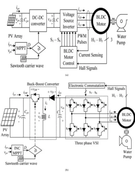
The existing literature exploring SPV
array-based BLDC motor-driven water pump is
based on a configuration shown in Fig.1. A dc–dc
converter is used for MPPT of an SPV array as
usual. Two phase currents are sensed along with
Hall signals feedback for control of BLDC motor,
resulting in an increased cost. The additional
control scheme causes increased cost and
complexity, which is required to control the speed
of BLDC motor. Moreover, usually a
voltage-source inverter (VSI) is operated with
high-frequency PWM pulses, resulting in an increased
switching loss and hence the reduced efficiency.
A DC–DC buck–boost converter is utilised to
extract the maximum power available from the
SPV array. And he additional functions of buck–
boost converter is soft starting and speed control of
the BLDC motor coupled to water pump, by
applying the MPPT algorithm appropriately. Owing
to the single switch and least number of reactive
components, this converter possesses very good
conversion efficiency and offers boundless region
for MPPT. This converter is operated in continuous
conduction mode (CCM) resulting in a reduced
stress on its power devices and components.
Furthermore, the switching loss of VSI is reduced
by adopting fundamental frequency switching
resulting in an additional power saving and hence
the enhanced efficiency. The phase currents as well
as the DC-link voltage sensors are completely
eliminated, offering simple and economical system
without sacrificing its performance. The speed of
BLDC motor is controlled, without any additional
control, through the variable DC-link voltage of
VSI. Moreover, the soft starting of BLDC motor is
achieved by proper initialization of MPPT
(a)
(b)
Fig. 1 Configuration of the SPV array fed BLDC motor driven water pumping system a) Conventional b)
Proposed
II. CONFIGURATION OF PROPOSED
SYSTEM & OPERATION
Fig. 1b shows the configuration of the proposed
SPV-based buck– boost converter fed BLDC motor
proposed system consists of an SPV array, a buck–
boost DC–DC converter, a VSI, a BLDC motor and
a water pump. As shown in Fig. 1b, the SPV array
generates the electrical energy and feeds the DC–
DC buck–boost converter. The insulated gate
bipolar transistor (IGBT) switch of the buck–boost
converter is operated through an incremental
conductance (INC) MPPT algorithm such that the
operation of the SPV array is optimized and the
BLDC motor has the soft starting. The buck–boost
converter is operated in CCM to reduce the stress
on the components and semiconductor devices.
Furthermore, the buck– boost converter feeds
power to the VSI, supplying the BLDC motor
coupled to a water pump. Switching sequence for
the VSI is provided by the electronic commutation
of BLDC motor. An electronic commutation is a
process of decoding the Hall Effect signals
generated by the inbuilt encoder of the motor
according to position of the rotor. The design and
control of the proposed system are elaborated in the
following sections.
III.
DESIGN
OF
THE
PROPOSED
SYSTEM
The various operating stages of the
configuration shown in Fig. 1b such as the SPV
array, the buck–boost converter and the water
pump are designed such that a satisfactory
operation is always accomplished under any kind
of change in solar isolation level. A BLDC motor
of 1.3 kW rated power is selected and each stage of
the proposed system are designed accordingly, as
follows.
Design of SPV array
An SPV array of 1.5 kW peak power
capacity, somewhat more than required by the
motor, is selected so that the performance of the
system is not affected by the losses associated with
the converters and the motor. The parameters of the
SPV array are estimated at the standard solar
isolation level of 1000 W/m2. A PV module
AP-100, manufactured by Astro power Inc. [49] with
peak power of 100 W, maximum voltage of 16.1 V
and maximum current of 6.2 A is considered to
design an SPV array of required capacity. First of
all, the voltage of the SPV array at MPP is selected
in view of the DC voltage rating of the BLDC
motor same as DC-link voltage of the VSI.
Selecting this voltage as 𝑉𝑚𝑝𝑝 = vpv= 241.5 V, the
other parameters are estimated as:
The current at MPP
(1)
where ppv = Pmpp = 1500 W is the peak power capacity.
Numbers of modules connected in series are as
(2)
Numbers of modules connected in parallel are as
where Vm and Im are voltage and current of a module at MPP.
Design of buck–boost converter
The SPV array voltage at MPP, vpv = 𝑉𝑚𝑝𝑝 = 241.5 V appears as the input voltage source, whereas
DC-link voltage of VSI, vdc appears as the output voltage of the buck–boost converter. The duty ratio, D of
buck–boost converter is estimated, using the input–output relationship as [50]
(4)
where Vdc = 310 V is rated DC-link voltage of VSI on the other hand, neglecting the buck–boost converter
losses, an average current flowing through DC link, Idc is as
(5)
An addition of the two currents
,
𝑖pv and Idc flow through the inductor, L. The inductor, L is estimated as [50](6)
Where fsw is the switching frequency of the buck–boost converter and Δ
I
L is an amount of ripple permitted inthe inductor current.
The highest and lowest frequencies of the VSI output voltage are considered to estimate the DC-link
capacitor, C [27, 48]. The highest value of VSI output voltage frequency, ωh(in rad/s) is calculated
corresponding to the rated speed of the motor (N rated = 3000 rpm) while the lowest value of VSI output
voltage frequency, ωl (in rad/ s) is calculated corresponding to the minimum speed of a motor required to pump
the water (N = 1100 rpm) as
(7)
(8)
where f is the frequency of VSI output voltage in hertz, N rated is rated speed of the BLDC motor and P is the
numbers of poles.
Since sixth harmonic component of VSI output voltage appears on DC link of VSI, limiting the voltage ripple,
ΔVdc in vdc to 1%, the DC-link capacitor, C is estimated corresponding to ωh and ωl as
(10)
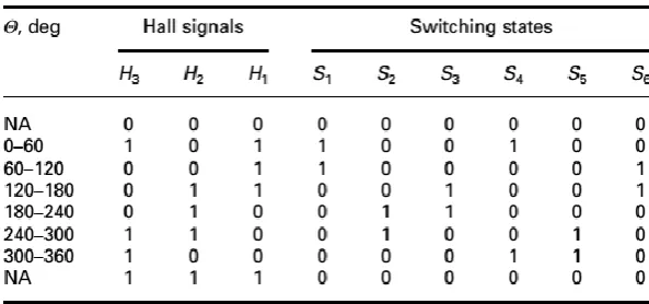
TABLE 1
Switching states for electronic commutation of BLDC motor
As per the estimation in (10), to ensure the satisfactory performance of the BLDC motor-pump, somewhat a higher value of C = 1500 μF is selected.
Design of water pump
A water pump is selected and is designed using its torque–speed characteristics as [15]
(11)
where Kp is a constant for selected water pump; TL is the load torque offered by pump; and ω is
rotational speed in rad/s.
IV.CONTROL
OF
THE
PROPOSED
SYSTEM
The controls of the proposed system:
namely, MPPT and electronic commutation of
BLDC motor are elaborated in the following
sections.
Maximum power point tracking
The MPPT technique is mostly used to
optimise the utilization of SPV array. An INC type
of MPPT technique [4–6] is used here because of
its high precision of tracking even under rapid
changes in the atmospheric conditions. The
perturbation size is wisely selected such that the
oscillation around the peak power point is avoided
and the soft starting of the BLDC motor is ensured
under all the possible variations in the solar
isolation level. A low perturbation size is selected
(0.001) to control the tracking speed. To achieve
the soft starting of motor, the output voltage of
buck– boost converter is controlled at starting by
initialising the duty ratio as zero. Therefore, as the
operating power point of SPV array moves toward
controlled rate. This results in a reduced rate of rise
of stator current, ensuring a soft starting.
Fig.2. Illustration of INC-MPPT with SPV
array Ppv−vpv characteristics
Electronic commutation
The switching signals for the VSI are
generated through the electronic commutation of
the BLDC motor [33, 34]. According to the angular
position of the rotor, the encoder provides three
Hall Effect signals. These Hall Effect signals are
logically converted into six switching pulses used
to operate the six IGBT switches of the VSI, as
shown in Table 1.
V. CLOSED LOOP SPEED CONTROL OF
BLDC MOTOR
In the sensored BLDC drive, hall sensors
or a shaft encoder is used to obtain the rotor
position information. The drive control system
consists of an outer speed loop for speed control
and an inner current loop for current control.
Conventionally three separate current sensors are
used to measure the phase currents. But here only
one current sensor is used, which is placed on the
DC link.
Speed control
The speed control block uses a
Proportional Integral (PI) controller. A PI
controller attempts to correct the error between a
measured process variable and desired set point by
calculating and then outputting a corrective action
that can adjust the process accordingly. The PI
controller calculation involves two separate modes
the proportional mode and the integral mode. The
proportional mode determine the reaction to the
current error, integral mode determines the reaction
based recent error. The weighted sum of the two
mode output as corrective action for the control
element. The PI controller is widely used in the
industry due to its ease in design and simple
structure. The PI controller algorithm can be
implemented as
(12)
Here the input to speed controller is the
speed error. The output of the controller is
considered as a reference torque. A limit is put on
the speed controller output depending on
permissible maximum winding currents.
Fig. 3 Matlab/Simulink circuit of Starting and steady-state performances of the proposed SPV array based
Buck-Boost converter-fed BLDC motor drive for water pump
(b)
(c)
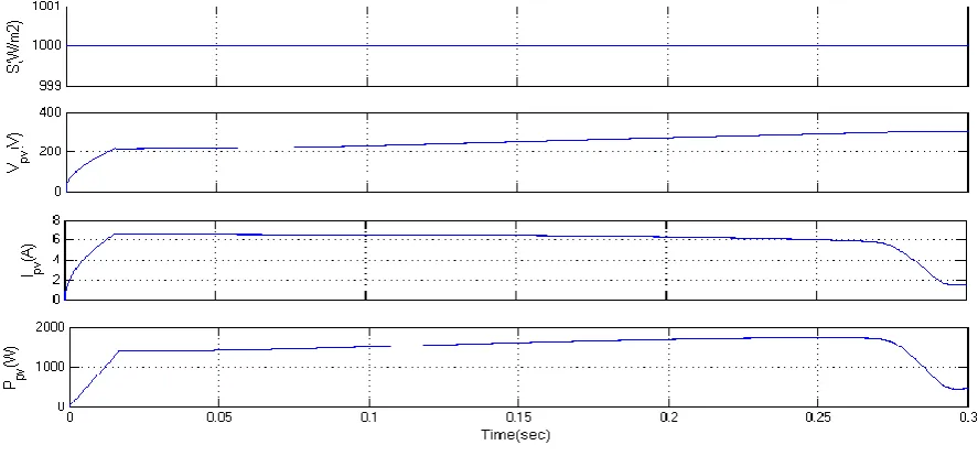
Fig.4 Starting and steady-state performances of the proposed SPV array based zeta converter-fed BLDC motor
drive for water pump. (a) SPV array variables. (b) Buck-Boost converter variables. (c) BLDC motor-pump
Fig.5 Matlab/Simulink circuit for Dynamic performance of SPV array-based Buck-Boost converter-fed BLDC
motor drive for water pump
(b)
(c)
Fig.6 Dynamic performances of the proposed SPV array-based zeta converter-fed BLDC motor drive for water
Fig.7 Matlab/Simulink circuit of SPV array-based Buck-Boost converter-fed BLDC motor drive Closed loop
control for water pumping system
Fig.9.Speed
VII. CONCLUSION
A solar photovoltaic array fed Buck-Boost
converter based BLDC motor has been proposed to
drive water-pumping system. The proposed system
has been designed, modelled and simulated using
MATLAB along with its Simulink and simpower
system tool boxes. Simulated results have
demonstrated the suitability of proposed water
pumping system. SPV array has been properly
sized such that system performance is not
influenced by the variation in atmospheric
conditions and the associated losses and maximum
switch utilization of Buck-boost converter is
achieved. Buck-Boost converter has been operated
in CCM in order to reduce the stress on power
devices. Operating the VSI in conduction mode
with fundamental frequency switching eliminates
the losses caused by high frequency switching
operation. Stable operations of motor-pump system
and safe starting of BLDC motor are other
important features of the proposed system.
REFERENCES