A Novel High-Gain Cavity Slot Antenna Based on Polarization
Twist Reflector for High Power Microwave Applications
Hong-Yin Zhang*, Fu-Shun Zhang, and Fan Zhang
Abstract—A novel high-gain and high-power cavity slot antenna is presented in this paper. The antenna consists of a slotted cavity cover, a driven antenna and a polarization twist reflector. The driven antenna is a balanced-fed dipole. And a 2×4 slots array is etched on the top surface of the cavity cover. To excite the cavity slots with uniform amplitude and phase, the polarization twist reflector is used here. Compared with the antenna without the twister, the gain is improved by almost 4.0 dB across the operating band. In addition, the field distributions of the proposed antenna are analyzed through simulation, which proves a high power-handling capacity of 3.94 MW. To verify the design, a prototype operating at 5.8 GHz band has been fabricated and measured. The measured maximum gain and radiation efficiency are 13.6 dBi and 95%, respectively.
1. INTRODUCTION
High power wireless transmission (HPWT) is increasingly popular in space solar power satellite research, which transmits the solar power generated in space to the ground via microwave [1, 2]. As a crucial component in the HPWT system, the transmitting antenna is typically designed to be a high-gain and high-power antenna array. Substantial efforts have been focused on the designs of array elements.
Generally, horns or reflectors as array elements are able to provide good radiation properties. However, they are often electrically large and bulky. Recently, some microstrip antennas with low-profile characteristics are reported [3–5]. The antenna in [3] consists of six U-slot radiating elements with a maximum gain of 19.4 dBi. For the antenna in [4], 16 elements are arranged in a ring to realize a high-gain property. Besides, the antenna in [5] using stacked patch structure can achieve a maximum gain of 16.2 dBi. Nevertheless, the feeding networks for these antennas are required, decreasing antenna efficiency and increasing structures complexity. Thus, having high-directivity antennas with a single element is interesting since it avoids the use of a feeding network [6–11]. In particular, the antenna using TE330 mode [6] can provide a measured peak gain of 13.6 dBi and peak antenna efficiency of 96%. In
addition, some antennas with EBG and FSS structures are proposed to obtain high-gain properties [12– 14]. By using the FSS structure in [13], gain performance is enhanced by 4.3 dB at most compared with the original antenna in the working frequency band. In [14], the cavity resonant antenna with 3×3 metal patch-type FSS can achieve a gain as high as 13.97 dBi. Unfortunately, dielectric materials of these antennas cannot handle high power, which makes them unsuitable for the HPWT system. To alleviate the above problems, several all-metal Fabry-Perot cavity (FPC) antennas and radial line antennas [15–18] are further designed. By stacking two FP cavities of different sizes, the antenna in [15] has a realized gain of 15.9 dBi and bandwidth of 10.3%. In [16], the antenna can achieve a maximum directivity level of about 18.5 dBic at 3.9 GHz. In addition, two novel radial line helical array antennas in [17, 18] are developed to realize directional radiation for high power microwave applications.
Received 2 May 2017, Accepted 10 July 2017, Scheduled 19 July 2017
* Corresponding author: Hong-Yin Zhang ([email protected]).
Inspired by the FPC antennas, a novel high-gain and high-power cavity slot antenna is proposed in this paper. No external feeding network is needed in this design. The antenna is simply fed by a driven dipole. Based on the polarization twist reflector, the cavity aperture with 2×4 slots can be excited with uniform amplitude and phase, thus the antenna can achieve a high-gain property. By comparison, the gain performance for the antenna without the twister can be improved by an average value of 4.0 dB within the whole operating band. Furthermore, simulated field distributions of the proposed antenna demonstrate that it can achieve a power-handling capacity of 3.94 MW, which is suitable for high power microwave applications. Additionally, the measured results coincide approximately with the simulated ones, which proves the feasibility of this antenna.
2. ANTENNA CONFIGURATION
Figure 1 shows the configuration of the proposed high-gain cavity slot antenna. The antenna can be divided into three parts, namely a slotted cavity cover, a driven antenna and a polarization twist reflector. The driven antenna is a balanced-fed dipole, which can excite electromagnetic fields inside the cavity. And its arm is 22 mm in total length, corresponding to about λ0/2 (λ0 is the free space
wavelength at 5.8 GHz). The height of the dipole from the polarization twist reflector is H0. In this design, the polarization twister is composed of 45◦-titled periodic metal-gratings and a ground plane. The distance between them is about 0.25λ0. Meanwhile, the overall size of the polarization twister is
139×53×14.5 mm3. The cavity cover is used as a slotted cavity radiator here. And a 2×4 slots array is etched on its top surface. As shown in Figure 1(a), the etched slots are distributed symmetrically along the +X/+Y axis. All the slots have a same size of 26.6×4 mm2. Besides, structures for installation convenience are also designed. It should be noted that each part of the antenna is processed separately and assembled as a whole finally. The detailed geometry and dimensions of the proposed antenna are given in Figure 1 and Table 1 after optimization using ANSYS HFSS.
(a)
(b) (c)
Figure 1. Configuration of the proposed antenna. (a) Front view; (b) Side view; (c) 3-D view.
3. ANTENNA DESIGN
3.1. Operating Principle of the Polarization Twist Reflector
Table 1. Dimensions of the proposed cavity slot antenna.
Parameter Value (mm) Parameter Value (mm) Parameter Value (mm)
L 139 S2 30 B0 1.4
W 53 SS 32 B1 3.2
L1 6.5 F1 22.6 W0 4.0
W1 2.6 F2 F1 H0 11.8
S0 5.0 F S 4.0 H1 20.2
S1 14.3 T 2.0 H2 10.5
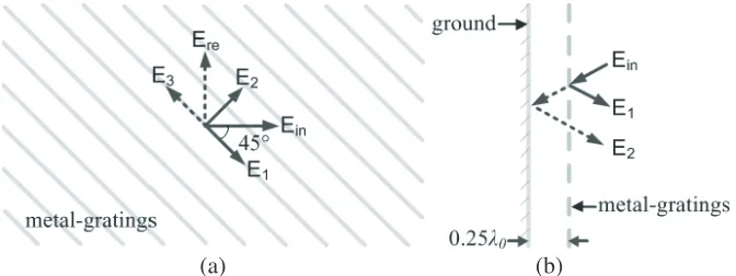
Ein polarized at a 45 angle with respect to the metal-gratings axes, as shown in Figure 2(a). When
the incident wave Ein impinges on the metal-gratings surface, it can be divided into two orthogonal
componentsE1 (parallel) and E2 (perpendicular). The metal-gratings are highly reflective for E1 and
nearly transparent for E2 [15, 16]. Then, the E1 is strongly reflected and becomes E3 while the E2
passes through metal-gratings and is reflected back after a distance of 0.5λ0 (0.25λ0×2). Consequently,
vectorsE2 andE3, which are in phase, combine each other in the upper space to produce a new vector
Ere. Thus, the origin field Ein is twisted and can excite the cavity slots with same polarizations.
(b) (a)
Figure 2. Analytical model of polarization twist reflector. (a) Top view; (b) Side view.
3.2. High Gain Performance
To obtain a high-gain property, the 2×4 slot array should be excited with uniform amplitude and phase at the same time. Nevertheless, with a traditional dipole fed at the center of the cavity, it is not easy to excite the whole antenna aperture. In order to alleviate this problem, a polarization twist reflector is selected here. As shown in Figure 1(a), E-fields of the driven dipole are along the +Y axis, while the polarization of the cavity slot is along the +X axis. Thus, its radiation fields could not radiate out of the cavity firstly and then are reflected back into the cavity. Due to the multiple reflections between the reflective surface and the ground, the output fields can excite the 2×4 slots array with uniform amplitude and phase. Finally, the proposed antenna can achieve larger radiation area and therefore the gain performance is improved across the whole frequency band.
(a) (b)
Figure 3. (a) E field distribution of the proposed antenna; (b) E field distribution of the antenna without polarization twister (E field of the dipole is arranged along the +X axis).
Table 2. Radiation properties of the antenna with/without polarization twister.
Frequency (GHz)
3-dB BW (deg) with twister inXOZ
3-dB BW (deg) with twister in Y OZ
Gain (dB) with twister
Gain (dB) without twister
5.75 48 24 13.0 9.6
5.80 46 24 13.9 9.7
5.85 46 22 14.0 9.7
3.3. High Power Performance
To achieve a high power-handling capacity, all-metal structures are used in this design. The E-field distribution of the feeding system is simulated and the result is shown in Figure 4 (corresponding to an input power of 1 W). In Figure 4(a), the maximum E field is approximately 25183 V/m. If we maintain the vacuum state in the feeding system, and assume the breakdown threshold to be 50 MV/m under vacuum condition [15], the power-handling capacity of this feeding system is (50×106/25183)2 = 3.94 MW. Besides, Figure 4(b) also depicts the field distribution of the antenna aperture. It can be seen that the maximum electric field is approximately 408 V/m. Thus, the element can reach a power-handling capacity of (3×10⁶/408)2 = 54.07 MW (taking the breakdown threshold to be 3 MV/m in the atmosphere) [16]. In conclusion, the feeding system is the key component to determine the antenna’s power-handling capacity. This is because of the smaller wire radius of the coaxial line and the bending structure in the feeding system. However, the antenna can reach a power-handling capacity at least 3.94 MW, which is suitable for high power applications.
(a) (b)
4. PARAMETRIC STUDY
To characterize the proposed cavity slot antenna, a parametric study is carried out in this section. And the effects of vital parameters, such as B0,H2, F1 and H0, on the resonant frequency and gain performance are discussed. In addition, all the other parameters not mentioned stay constant as shown in Table 1 during this process.
4.1. Effect of the Width B0 of the Metal-Gratings
First, the effect of the metal-gratings dimension on the antenna performance is studied. Figure 5 depicts the simulated reflection coefficient and realized gain of the proposed antenna with different gratings dimension B0. It can be seen from Figure 5(a) that, as B0 decreases, the resonant frequency shifts upwards. In Figure 5(b), for different B0, the gains of the antenna almost stay the same in the lower band while change greatly in the upper band. Due to highly reflective property for one polarization component of the driven dipole, the parameter B0 affects the efficiency of polarization twister greatly. To obtain a better impedance matching centered at 5.8 GHz and gain performance,B0 is set as 1.4 mm.
(a) (b)
Figure 5. Simulated |S11|and realized gain of the cavity slot antenna for different B0 = 1.6, 1.4 and
1.2 mm. (a) |S11|; (b) Realized gain.
4.2. Effect of the Distance H2 between the Metal-Gratings and Ground
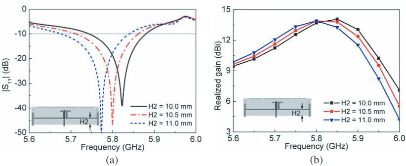
The effect of the distance H2 between the metal-gratings and ground is studied next. Figure 6 demonstrates the simulated reflection coefficient and realized gain of the proposed antenna with different distanceH2. With reference to Figure 6(a), it can be seen that the resonant frequency shifts downwards as H2 increases. Additionally, the simulated gain of the antenna has a similar trend as the reflection coefficient across the whole band. According to the first part in section three, H2 should be set asλ0/4
to obtain perfect polarization twist property. However, due to the existence of inclined polarizations and metal walls, different distances are optimized carefully. Finally, the distanceH2 is selected as 10.5 mm.
4.3. Effect of the Length F of the Cavity Slots
The effect of cavity slots on the simulated reflection coefficient of the proposed antenna is also investigated. As shown in Figure 7, it can be seen that the length F1 of cavity slots has a great effect on the resonant frequency. Actually, it can be expected that a longer cavity slot should have a lower resonant frequency. As radiation elements, the cavity slots not only affect pattern properties but also determine the impedance matching to some extent. In addition, the variations of|S11|withL1 are
(a) (b)
Figure 6. Simulated |S11| and realized gain of the cavity slot antenna for different H2 = 10.0, 10.5
and 11.0 mm. (a)|S11|; (b) Realized gain.
Figure 7. Simulated|S11|of the proposed cavity
slot antenna for different F1.
Figure 8. Simulated|S11|of the proposed cavity
slot antenna for different H0.
4.4. Effect of the Height H0 of the Driven Dipole
Figure 8 shows the simulated reflection coefficient for different heights H0 of the driven dipole. As shown in Figure 8, the resonant frequency shifts downwards asH0 increases. As we known, the height
H0 for a conventional dipole isλ0/4 at 5.8 GHz. Here, the height H0 from the polarization twister is set
as 12.5 mm initially. By optimizing the dimension of the dipole, the parameterH0 is chosen as 11.8 mm (∼λ0/4) finally.
In summary, the width and distance (B0 and H2) have great effects on the resonant frequency of the proposed antenna. By adjusting the parameters (B0 and H2) carefully, the resonant mode can be tuned centered at 5.8 GHz. Additionally, the cavity slots and dipole dimensions (F1 and H0) not only affect the resonant frequency but also have great effects on impedance matching. Therefore, properties of these vital parameters can be used to greatly simplify the design process.
5. EXPERIMENTAL RESULTS AND DISCUSSION
(a) (b)
Figure 9. (a) Top view of the fabricated antenna; (b) 3-D view of the antenna without cavity cover.
Figure 10. Simulated and measured|S11|of the proposed antenna.
(a) (b)
Figure 11. Simulated and measured radiation patterns at 5.8 GHz (a) in the xoz plane (ϕ= 0◦) and (b) in the yoz plane (ϕ= 90◦).
The simulated and measured |S11| are depicted in Figure 10, and good agreement between them
is obtained. With reference to the figure, it is clearly observed that the simulated and measured 10-dB impedance bandwidths (|S11| < −10 dB) are 2.6% (5.71–5.86 GHz) and 4.3% (5.65–5.90 GHz),
radiates directional fields. The measured 3-dB beamwidths in thexoz and yoz planes are 47◦ and 26◦, respectively. And within the 3-dB beamwidths, the cross-polarization levels for two principal planes are lower than −40 dB. Due to metal backed-cavity structure, the front-to-back ratio of the antenna is as large as 17 dB.
Finally, the simulated and measured gains and radiation efficiencies across the operating band are shown in Figure 12. In Figure 12, the measured gains from 5.5 to 13.6 dBi at θ = 0◦ and efficiencies of 90.1%–95.3% are obtained within the impedance bandwidth, respectively. The difference between simulated and measured efficiencies may be attributed to metal loss. And the antenna can provide a maximum gain of 13.6 dBi at 5.8 GHz, proving the good directional property of the prototype.
Figure 12. Simulated and measured gains and radiation efficiencies versus frequencies.
6. CONCLUSION
A novel high-gain cavity slot antenna has been investigated and fabricated in this paper. Based on the polarization twist reflector, a 2×4 slots array can be excited with uniform amplitude and phase to obtain a high-gain property. And all-metal structures for the antenna can achieve a high power-handling capacity. Different key parameters also have been studied, which can greatly simplify the design process. In addition, the measured results show that the antenna operates at 5.8 GHz, which agree well with the simulated results. Due to its advantages of high gain, high radiation efficiency and high power-handling capacity, the proposed antenna is a promising array element for high power wireless transmission applications.
ACKNOWLEDGMENT
This work was supported by the Fundamental Research Funds for Central University under Grant No. SPSZ02.
REFERENCES
1. Sasaki, S., K. Tanaka, and Advanced Mission Research Group, “Wireless power transmission technologies for solar power satellite,” IEEE MTT-S Int. Microwave Workshop Ser. Innovative. Wireless Power Transmission, Technol. Syst. Appl., 3–6, 2011.
3. Chen, H. D., C. Y. D. Sim, J. Y. Wu, and T. W. Chiu, “Broadband high-gain microstrip array antennas for WiMAX base station,” IEEE Trans. Antennas Propag., Vol. 60, No. 8, 3977–3980, Aug. 2012
4. Jiang, Y. H., W. G. Yi, and H. C. Sun, “A new focused antenna array with circular polarization,” Microw. Opt. Technol. Lett., Vol. 57, No. 12, 2936–2939, Dec. 2015.
5. Yang, T. Y., W. Hong, and Y. Zhang, “Wideband high-gain low-profile dual-polarized stacked patch antenna array with parasitic elements,” Microw. Opt. Technol. Lett., Vol. 57, No. 9, 2012–2016, Sep. 2015.
6. Han, W. W., F. Yang, and H. J. Zhou, “Slotted substrate integrated cavity antenna using TE330
mode with low profile and high gain,”Electron. Lett., Vol. 50, 488–490, 2014.
7. Razavi, S. A. and M. H. Neshati, “Development of slot array antenna using a multiresonant SIW cavity,” Microw. Opt. Technol. Lett., Vol. 55, No. 11, 2763–2767, Nov. 2013.
8. Liu, Y., Y. W. Hao, and S. X. Gong, “Low-profile high-gain slot antenna with Fabry-P´erot cavity and mushroom-like electromagnetic band gap structures,”Electron. Lett., Vol. 51, 305–306, 2015. 9. Jayasinghe, J. M. J. W., J. Anguera, and D. N. Uduwawala, “Genetic algorithm optimization of a
high-directivity microstrip patch antenna having a rectangular profile,”Radioengineering, Vol. 22, No. 3, 700–707, Sep. 2013.
10. Anguera, J., C. Puente, C. Borja, R. Montero, and J. Soler, “Small and high directivity bowtie patch antenna based on the Sierpinski fractal,”Microwave and Optical Technology Letters, Vol. 31, No. 3, 239–241, Nov. 2001.
11. Anguera, J., J. P. Daniel, C. Borja, J. Mumbr´u, C. Puente, T. Leduc, N. Laeveren, and P. Van Roy, “Metallized foams for fractal-shaped microstrip antennas,” IEEE Antennas and Propagation Magazine, Vol. 50, No. 6, 20–38, Dec. 2008.
12. Elwi, T. A., A. I. Imran, and Y. Alnaiemy, “A miniaturized lotus shaped microstrip antenna loaded with EBG structures for high gain-bandwidth product applications,” Progress In Electromagnetics Research C, Vol. 60, 157–167, 2015.
13. Cong, L. L., X. Y. Cao, W. Q. Li, and Y. Zhao, “A new design method for patch antenna with low RCS and high gain performance,” Progress In Electromagnetics Research Letter, Vol. 59, 77–84, 2016.
14. Muhammad, N., H. Umair, Z. U. Islam, Z. Khitab, I. Rashid, and F. A. Bhatti, “High gain FSS aperture coupled microstrip patch antenna,” Progress In Electromagnetics Research C, Vol. 64, 21–31, 2016.
15. Muhammad, S. A., R. Sauleau, and H. Legay, “Small-size shielded metallic stacked Fabry-Perot cavity antennas with large bandwidth for space applications,” IEEE Trans. Antennas Propag., Vol. 60, No. 2, 792–802, Feb. 2012.
16. Muhammad, S. A., R. Sauleau, G. Valerio, and H. Legay, “Self-polarizing Fabry-Perot antennas based on polarization twisting element,”IEEE Trans. Antennas Propag., Vol. 61, No. 3, 1032–1040, Mar. 2013.
17. Li, X. Q., Q. X. Liu, X. J. Wu, L. Zhao, J. Q. Zhang, and Z. Q. Zhang, “A GW level high-power radial line helical array antenna,” IEEE Trans. Antennas Propag., Vol. 56, No. 9, 2943–2948, Sep. 2008.
18. Li, X. Q., Q. X. Liu, J. Q. Zhang, and L. Zhao, “16-element single-layer rectangular radial line helical array antenna for high-power applications,”IEEE Antennas Wireless Propag. Lett., Vol. 9, 708–711, 2010.
19. Hwang, K. C., “Optimization of broadband twist reflector for Ku-band application,” Electron. Lett., Vol. 44, 210–211, 2008.