Interference Analysis and Experimental Results of Passive UHF
RFID Systems in Sub-1 GHz Wireless Communications Systems
Ji-Hong Kim1, Jong-Won Kwon2, Jin-Yong Kim2, Min-Gyo Jeong1, Sang-Hyeon Bae1, and Wang-Sang Lee1, *
Abstract—As ultra high frequency (UHF) radio frequency identification (RFID) technology, a smart recognition technology, has been gradually spreading to various applications, and several sub-1 GHz wireless technologies are being standardized and developed. As such technologies operate at a specific frequency band (902–928 MHz industrial, scientific, and medical bands), the impact of RF interference due to performance degradation of UHF RFID technology on the interference signal is emerging as a new obstacle. In this paper, we investigate the interference analysis and experimental results of passive UHF RFID systems in sub-1 GHz wireless communications systems. By considering interference signal frequency and power, interference deployment, antenna polarization, RF system-level analysis and experimental verification are conducted to evaluate the impact of performance degradation in the UHF RFID system on the interference signal.
1. INTRODUCTION
Due to the complexity of demand in the manufacturing environment, it is necessary to quickly detect changes in the market and reflect them in production strategies. Accordingly, manufacturing environments are demanding smart manufacturing technology through the fusion of conventional manufacturing and information and communication technologies (ICT). Radio-frequency identification (RFID), a key technology in smart manufacturing, is an automatic identification method, relying on storing and remotely retrieving data using RFID tags. Since an RFID tag is a smart label that can be incorporated into people, animals, and products for the purpose of information provision (identification) using radio waves, in recent years, RFID systems have become very popular in many service industries, purchasing and distribution logistics, industry, manufacturing companies and material flow systems. In particular, ultra high frequency (UHF) RFID systems, which offer several advantages such as long recognition range, multiple ID sensing, and low cost have been widely utilized instead of barcodes [1–6]. Due to radio propagation characteristics, many electromagnetic interference (EMI) problems, such as tag-to-tag interference, reader-to-tag interference and reader-to-reader interference, have appeared and are being reported in the initial RFID application environment [7–9]. RFID system performance can be degraded as a result of these EMI problems. To solve these issues, various anti-collision systems and algorithms in [10], interference suppression techniques based on time division in [11], or switched beamforming antennas in [12, 13] have been utilized.
With the increasing demand for industrial internet of things (IIoT) in smart manufacturing, several sub-1 GHz unlicensed wireless technologies, such as LoRa, Sigfox, Wi-SUN, Z-Wave, and IEEE 802.11ah, as well as UHF RFID technology, are emerging and being standardized [14–17]. Table 1 summarizes a comparison of key features of sub-1 GHz wireless communication technologies in the US. Most of these
Received 8 April 2017, Accepted 14 July 2017, Scheduled 3 August 2017
* Corresponding author: Wang-Sang Lee ([email protected]).
1 Department of Electronic Engineering/Engineering Research Institute (ERI), Gyeongsang National University (GNU), 501
Jinju-daero, Jinju 52828, Republic of Korea. 2RF Application Technology Center, Korea Testing Laboratory (KTL), 10, Chungui-ro, Jinju
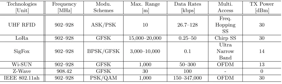
Table 1. Key features of sub-1 GHz unlicensed wireless communication technologies in the US. Technologies [Unit] Frequency [MHz] Modu. Schemes Max. Range [m] Data Rates [kbps] Multi. Access TX Power [dBm]
UHF RFID 902–928 ASK/PSK 10 26.7–128
Freq. Hopping
SS
30
LoRa 902–928 GFSK 15,000–20,000 0.25–50 Chirp SS 30
SigFox 902–928 BPSK/GFSK 3,000–10,000 0.1
Ultra Narrow
Band
14
Wi-SUN 902–928 GFSK 1,000 50–300 OFDM 13
Z-Wave 908.42 GFSK 30 100 - 0
IEEE 802.11ah 902–928 PSK/QAM 1,000 150–347,000 OFDM 30
technologies use an operating frequency band of 902–928 MHz, which is one of the industrial, scientific, and medical (ISM) bands in the US, commonly abbreviated as the 915 MHz ISM band. To manage an interference-free frequency spectrum, the Federal Communications Commission (FCC), an independent agency of the US government responsible for implementing and enforcing communication laws and regulations, allows an electrical field strength of 50 mV/m at a distance of 3 m in the 915 MHz ISM band, and the harmonics limit is one hundredth of the fundamental level, 0.5 mV/m. These correspond to an effective isotropic radiated power (EIRP, the product of the peak transmit power and isotropic antenna gain) of−1.23 dBm and−41.23 dBm, respectively. When applying spread spectrum techniques such as frequency hopping spread spectrum (FHSS), chirp spread spectrum (CSS), or direct sequence spread spectrum (DSSS), which can be less likely to interfere with other systems than single frequency transmitters, the maximum EIRP allowed in the 915 MHz ISM band is 36 dBm.
Although wireless electronic devices not only satisfy such radio wave regulations on the dedicated 915 MHz ISM frequency band but also pass standard immunity testing requirements, the potential EMI issues among various wireless technologies including UHF RFID technology have been increasing [18, 19]. In the case of adjacent frequency bands, an interference analysis of UHF RFID signals (865–867 in EU and 902–928 MHz in US) for GSM signals (824–849 MHz in US and 876–915 MHz in EU) was performed [20]. The EMI effects on NFC or LoRa systems by UHF RFID signals have been studied experimentally [21, 22]. Previous studies that achieved EMI effects between UHF RFID technology and other wireless technologies were conducted in a restricted system deployment [23, 24]. Generally, a passive UHF RFID tag with a dipole antenna has influence on wave polarization. Additionally, since the backscattered signal in a passive RFID tag is susceptible to external noise, the UHF RFID system requires a performance evaluation based on ambient noise conditions.
Over the past several years, UHF RFID technology has become widespread throughout the industry to manage inventory and improve productivity. Recently, as low power long range wireless technologies for IIoT have been spreading for smart manufacturing in [14], the EMI effects of the installed UHF RFID technology attract attention increasingly. To examine the effect of RFID signal on interference signal, we investigate the EMI effects of UHF RFID system performance in other sub-1 GHz wireless communications systems by analyzing a simplified RF system link simulation and by evaluating experimentally performance impacts against the EMI signals in this paper.
2. INTERFERENCE ANALYSIS
Typically, the power (Pr) received from a wireless transmitting system with a distance of R can be calculated using the Friis Transmission Equation in (1):
Pr = Pt·GtGrλ
2
(4πR)2 ·Limp·Lpol·e−αR
= Pt·GtGrλ
2
(4πR)2 ·(1− |Γt|
2)(1− |Γ
where Pt, Gt, Gr, λ,Limp, Γt, Γr, Lpol, at, ar, α are the transmitted power, gain of the transmitting antenna, gain of the receiving antenna, wavelength, impedance mismatch loss, reflection coefficients of transmitting and receiving antennas, polarization loss, polarization vectors of the transmitting and receiving antennas, and absorption coefficient of the intervening medium (zero in free space), respectively.
By considering the EMI effects of an RFID signal against the sub-1 GHz wireless communication signal in Table 1, we analyze the impact of RF interference in a passive UHF RFID system by a Gaussian frequency shift keying (GFSK)-modulated interference signal. The RF/wireless communication system design software, a visual system simulator (VSS) by NI AWR, is utilized. Fig. 1 shows an overall block diagram of an RFID tag-to-reader communication link configured to analyze the performance impact in a UHF RFID system under an interference signal. Its block diagram consists of the backscatter signal generation of the RFID tag, GFSK-modulated interference signal generation with a frequency sensitivity of 17.675 Hz/V, communication channel, and demodulation of UHF reader. To simplify the simulation analysis, RF front-end circuits, such as transmit and receive antennas, a bandpass filter, an RF switch for time division multiplexing (TDD), an amplifier, and a down-conversion mixer, have been omitted. To compare the EMI effects of a UHF RFID system assumed to be an LOS (line of sight) communication system with an additive white Gaussian noise (AWGN) communication channel, the reflection characteristics by the environment are not considered. The backscattered RFID and interference signals are reduced by antenna characteristics (Lpol,Gt, andGr) and the operating distance (R). The modulation index of the UHF RFID system is 0.8, and the data rate of those signals is 50 kpbs.
Random Signal (Interferer)
Gaussian Filter FSK Modulation
Carrier GFSK Modulation (Interference Signal)
ASK Modulation (RFID Tag Backscattered Signal)
Carrier Random Signal
(Data) ASK Modulation
Attenuation
AWGN Combiner
Communication Channel ASK Demodulation (Receiving Part of a RFID Reader)
BER ASK Demodulation
DAC
ADC Integrate
AVG NEG
ADD
DAC
Figure 1. Overall block diagram of an RFID tag-to-reader communication link configured to analyze the performance impact in an UHF RFID system under an interference signal.
(a) (b) (c)
(b)
(a) (c)
(e)
(d) (f)
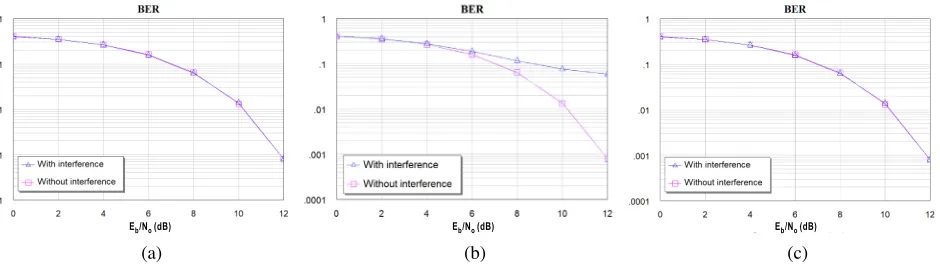
Figure 3. Simulated BER performance of an UHF RFID system with an ASK signal against a GFSK-modulated interference signal at 920 MHz with regard to power differences between the backscattered RFID and interference signal powers (Sr,Si): (a) Sr =Si+ 30 dB, (b) Sr=Si+ 20 dB, (c)Sr =Si+ 10 dB, (d)Sr =Si, (e) Si=Sr+ 10 dB, (f)Si=Sr+ 20 dB.
The bit error rate (BER) can be obtained by a function of signal-to-noise ratio (SNR) Eb/N0, where
Eb is the energy received per information bit, andN0 is the noise power spectral density.
Figure 2 represents the simulated BER performance of an UHF RFID system with a 920 MHz amplitude shift keying (ASK) signal against a GFSK-modulated interference signal with different operating frequencies (915 MHz, 920 MHz, 925 MHz). When the backscattered RFID signal power (Sr) is 6 dB higher than the interference power (Si), an in-band interference signal has a greater influence on the BER of an RFID tag than adjacent-band interference signals in Fig. 2(b). However, the interference signals on the adjacent frequency bands have little influence on the RFID signal in Figs. 2(a) and 2(c). Fig. 3 describes the simulated BER performance results of a UHF RFID system with an ASK signal against a GFSK-modulated interference signal at 920 MHz with regard to power differences between the backscattered RFID and interference signal powers (Sr, Si). If the backscattered RFID signal power (Sr) is 30 dB higher than the interference signal power (Si), as shown in Fig. 3(a), there is very little interference effect in terms of the RFID system. At 915 MHz, the free-space path loss at a distance of 1 m is approximately 30 dB. The backscattered tag signal is reduced to free-space path loss by the distance from the RFID reader. Therefore, it is the same as the effect that the interference source is relatively far away. However, if the power difference between the RFID and interference signal is less than 20 dB, the BER performance is gradually degraded at the high SNR (Eb/N0 ≥10 dB), as shown
in Figs. 3(b) and 3(c). Furthermore, if the interference signal power is equal to or greater than the RFID signal power, the BER performance in the RFID system due to the interference effect is significantly worse, as shown in Figs. 3(d), 3(e) and 3(f). Therefore, as the requiredEb/N0 of the UHF RFID system
increases, the impact of EMI increases.
3. EXPERIMENTAL VERIFICATIONS
chamber to take into account the practical application environment which means the ground reflection consideration of the backscattered and interference signals. The device under test (DUT) is a passive UHF RFID tag (ALN-9710 by Alien Technology), which included a Higgs-4 IC, and was designed to meet EPCglobal Gen2 and ISO/IEC 18000-6C standards in UHF RFID bands (840–960 MHz) for worldwide operation. The DUT was arranged in the horizontal polarization direction. A CISC RFID Xplorer test instrument was used to test for tag sensitivity, communication range and backscatter measurements because of its high receiver sensitivity. The interference signal generator and antenna used were an Agilent MXG vector Signal generator (N5182A), which can generate a GFSK-modulated signal with a 500 kHz bandwidth and a double-ridged horn antenna (Model 3115 by ETS-Lindgren) with a linear polarization, respectively. In Fig. 3(c), when Sr is about 10 dB higher than the Si, the impact of the interference signal starts to appear. Considering the experimental setup margin of 3 dB, the Si was set to maximum 17 dBm, which is 13 dB less than the Sr.
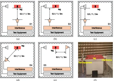
3.1. Performance Test 1: System Deployment of an Interference Signal
To test the performance impact of UHF RFID systems with regard to system deployment of an interference signal, the experimental setup was conducted using five interference testing setups, as shown in Fig. 4. Depending on the operating distance and placement of the interfering signal, the read range change rate (RRCR, %) based on the measurement results can be calculated using Eq. (2):
RRCR (Read range change rate, %) = Read range with interference
Read range without interference ×100. (2)
Figure 5 shows the RRCR comparison results of a UHF RFID system based on the operating frequency (915 MHz, 920 MHz, 925 MHz) and distance (0.3 m, 1 m, 3 m) of an interfering signal (Si = 17 dBm). When the interference signal exists at a distance of 0.3 m, as shown in Figs. 5(a), 5(b), and 5(c), the in-band interference signal has a greater influence on the RF sensitivity of the RFID
(b)
(a) (c)
(e)
(d) (f)
(b)
(a) (c)
(e)
(d) (f)
(h)
(g) (i)
Figure 5. The read range change rate (RRCR, %) comparison results of an UHF RFID system based on the operating frequency (915 MHz, 920 MHz, 925 MHz) and distance (0.3 m, 1 m, 3 m) of an interfering signal (Si = 17 dBm): (a) 915 MHz at 0.3 m, (b) 920 MHz at 0.3 m, (c) 925 MHz at 0.3 m, (d) 915 MHz at 1 m, (e) 920 MHz at 1 m, (f) 925 MHz at 1 m, (g) 915 MHz at 3 m, (h) 920 MHz at 3 m, (i) 925 MHz at 3 m.
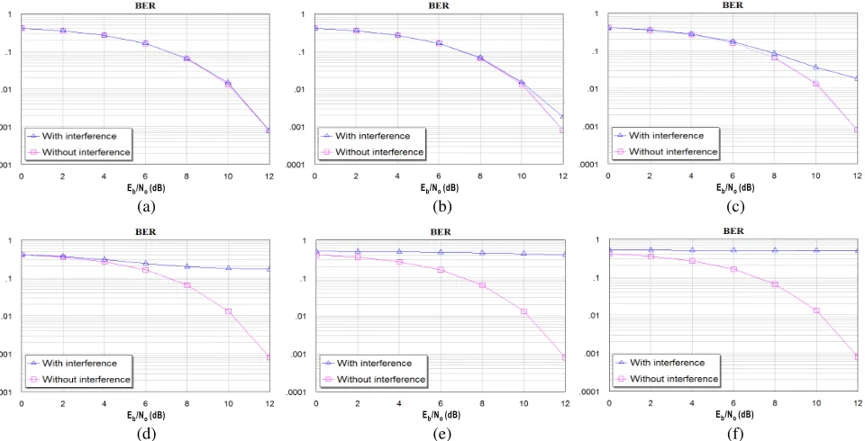
tag than adjacent-band interference signals, regardless of the deployment of an interference signal. Furthermore, the RF sensitivity of the RFID tag at the deployment setups (D2 and D3) is hardly affected by strong adjacent-band interference signals. At 1 m, as shown in Figs. 5(d), 5(e), and 5(f), the in-band interference signal has a greater influence on the RF sensitivity of the RFID tag than adjacent-band interference signals by particular location (D2 and D5) of an interference signal, and the RF sensitivity of the RFID tag at all deployments is almost unaffected by strong adjacent-band interference signals. Figs. 5(g), 5(h), and 5(i) show that the RF sensitivity of an RFID tag at all deployments is almost unaffected by weak in-band and adjacent-band interference signals. As shown in Fig. 5, it can be seen that the farther the operating distance is, the fewer the influence of the interference signal is, and the influence of the interference signal is related to the operating frequency of the interference source and the operation distance (Si).
3.2. Performance Test 2: RFID Tag Angular Selectivity
signal, and its experimental setup is shown in Fig. 6.
From Eq. (1), the theoretical forward read range (TFRR, m) using a test instrument in a free space can be calculated by (3):
TFRR (Theoretical forward read range, m) = λ 4π
EIRP·Gr·Limp·Lpol
Pth , (3)
whereλ,EIRP,Gr,Pth,Limp, andLpol are the wavelength, product of the transmitted power (Pt) and
(a) (b)
Figure 6. Experimental setup for the performance test of an UHF RFID system with regard to antenna orientation of an RFID tag on an interference signal: (a) test setup geometry and (b) its photo.
(b)
(a) (c)
(e) (d)
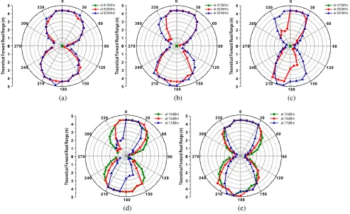
antenna gain (Gt) of the RFID reader, gain of the RFID tag antenna, minimum threshold power of the RFID tag IC, impedance mismatch loss, and polarization loss, respectively.
To evaluate the RFID tag performance at each operating frequency by an interference signal, Fig. 7 shows the TFRR comparison results based on experimental results with regard toSi (10 dBm, 14 dBm, 17 dBm) at 915 MHz and different operating frequencies (915 MHz, 920 MHz, 925 MHz) ofSr. It can be seen that the impact of the read range performance of the UHF RFID tag is increased by reducing the read range and coverage as the interference signal power increases.
4. CONCLUSION
This paper presents the EMI effects of a passive UHF RFID system on a GFSK-modulated wireless interference signal within the 915 MHz ISM frequency band using an RF system-level link analysis and experimental verifications such as read range change rate (RRCR) and theoretical forward read range (TFRR) based on experimental measurements. Based on our results, RFID performance can be degraded by the interference signal power and its signal wave polarization as well as the interference deployment. In order to prevent the performance degradation of UHF RFID technology due to the RF interference phenomenon in a practical application environment, standardization of the specific test evaluation method concerning the interference effect is required. In addition, it is also required to analyze the EMI effects by RFID signals in practical application environments where various wireless systems exist.
ACKNOWLEDGMENT
This work was supported by the Industrial Technology Innovation Program (No. 10069189) of the of the Korea Evaluation Institute of Industrial Technology (KEIT) and Human Resources Program in Energy Technology (No. 20174030201440) of the Korea Institute of Energy Technology Evaluation and Planning (KETEP) granted financial resource from the Ministry of Trade, Industry & Energy (MOTIE), Republic of Korea.
REFERENCES
1. Weyrich, M., J.-P. Schmidt, and C. Ebert, “Machine-to-machine communication,” IEEE Software, Vol. 31, No. 4, 19–23, 2014.
2. Tu, M., J.-H. Lin, R.-S. Chen, K.-Y. Chen, and J.-S. Jwo, “Agent-based control framework for mass customization manufacturing with UHF RIFD technology,” IEEE System Journal, Vol. 3, No. 3, 343–359, 2009.
3. Kim, M. and K. Kim, “Automated RFID-based identification system for steel coils,” Progress In Electromagnetics Research, Vol. 131, 1–17, 2012.
4. Paredes, F., G. Zamora, S. Zuffanelli, F. J. Herraiz-Martinez, F. Mart´ın, and J. Bonache, “Free-space and on-metal dual-band tag for UHF-RFID applications in Europe and USA,” Progress In Electromagnetics Research, Vol. 141, 577–590, 2013.
5. Huang, H.-F. and B. Wang, “A reconfigurable dual-broadband circularly polarized antenna by orthgonal slot technique for RFID reader,” Progress In Electromagnetics Research Lett., Vol. 68, 105–111, 2017.
6. Ding, K. and P. Jiang, “RFID-based production data analysis in an IoT-enabled smart job-shop,”
IEEE/CAA Journal of Automatica Sinica, Vol. PP, No. 99, 1–11, 2017 (To be published).
7. Lazaro, A., D. Girbau, and R. Villarino, “Effects of interferences in UHF RFID systems,”Progress In Electromagnetics Research, Vol. 98, 425–443, 2009.
8. Bekkali, A., S. Zou, A. Kadri, M. Crisp, and R. V. Penty, “Performance analysis of passive UHF RFID systems under cascaded fading channels and interference effects,” IEEE Trans. on Wire. Comm., Vol. 14, No. 3, 1421–1433, 2015.
10. Zhu, L. and T.-S. P. Yum, “A critical survey and analysis of RFID anti-collision mechanisms,”
IEEE Comm. Magaz., Vol. 49, No. 5, 214–221, 2011.
11. Khadka, G. and S.-S. Hwang, “Tag-to-tag interference suppression technique based on time division for RFID,”Sensors, Vol. 17, No. 78, 1–18, 2017.
12. Lee, W.-S., H.-S. Tae, and J.-W. Yu, “Quadruple-feed beam-controlled antenna array for the localisations of ultra-high-frequency radio-frequency identification tags,”IET Micro., Ant.&Prop., Vol. 9, No. 9, 923–932, 2015.
13. Li, J., X. Han, H. Zhang, and W. Shi, “Suppressing multipath interference by using smart antenna for passive UHF RFID system,” 2016 Int’l Conf. on Infor. Eng. and Comm. Tech. (IECT 2016), 1–6, 2016.
14. Krupka, L., L. Vojtech, and M. Neruda, “The issue of LPWAN technology coexistence in IoT environment,” 2016 17th Int’l Conf. on Mechat. — Mechatronika (ME), 2016.
15. Torabi, N., K. Rostamzadeh, and V. C. M. Leung, “IEEE 802.15.4 beaconing strategy and the coexistence problem in ISM band,”IEEE Trans. on Smart Grid, Vol. 6, No. 3, 1463–1472, 2015. 16. Samuel, S. S. I., “A review of connectivity challenges in IoT-smart home,” 2016 3rd MEC Int’l
Conf. on Big Data and Smart City, 2016.
17. Park, M., “IEEE 802.11ah: sub-1-GHz license-exempt operation for the internet of things,” IEEE Comm. Magaz., Vol. 53, No. 9, 145–151, 2015.
18. Guerrieri, J., “RFID and EMC,”IEEE Electrom. Compat. Magaz., Vol. 1, No. 3, 91–91, 2012. 19. Novotny, D. R., J. R. Guerrieri, and D. G. Kuester, “Potential interference issues between FCC part
15 compliant UHF ISM emitters and equipment passing standard immunity testing requirements,”
IEEE Electrom. Compat. Magaz., Vol. 1, No. 3, 92–96, 2012.
20. Brunner, B., F. Pfeiffer, K. Finkenzeller, E. Biebl, F. H¨ochstfrequenztechnik, and U. M¨unchen, “Impact of GSM Interference on passive UHF RFIDs,” Smart Sys. Tech. 2015, Europ. Conf. on Smart Objects, Systems and Tech., 1–7, 2015.
21. Mattei, E., E. Lucano, F. Censi, M. Triventi, and G. Calcagnini, “Provocative testing for the assessment of the electromagnetic interference of RFID and NFC readers on implantable pacemaker,” IEEE Trans. on Electrom. Comp., Vol. 58, No. 1, 314–322, 2016.
22. Lauridsen, M., B. Vejlgaard, I. Z. Kov´acs, H. Nguyen, and P. Mogensen, “Interference measurements in the european 868 MHz ISM band with focus on LoRa and SigFox,”Wire. Comm.
and Netw. Conf. (WCNC 2017), 1–6, 2017.
23. Fu, Y., W. Hong, S. Li, and J. Zou, “Experimental study on wireless interference in RFID system,”
11th Int’l Conf. on Wireless Comm., Networking and Mobile Computing (WiCOM 2015), 2015.