ISSN(Online): 2320-9801
ISSN (Print): 2320-9798
I
nternational
J
ournal of
I
nnovative
R
esearch in
C
omputer
and
C
ommunication
E
ngineering
(An ISO 3297: 2007 Certified Organization)
Vol. 3, Issue 9, September 2015
An Improved Energy Efficient Protocol for
Clock Synchronization in Wireless Sensor
Networks
Alina John, P Darsana
M. Tech Student, Dept. of ECE, Amal Jyothi College of Engineering, Kottayam, Kerala, India.
Assistant Professor, Dept. of ECE, Amal Jyothi College of Engineering, Kottayam, Kerala, India.
ABSTRACT: Wireless Sensor Networks require accurate time synchronization. Recharging the battery of wireless sensor nodes in remote, hazardous environments is impractical. Since the capacity of battery is usually low and applications need more life time, nodes should use their energy in an efficient way. Most of the sensors’ energy is consumed by algorithm for clock synchronization, by using message exchange between the sensor nodes. Using an energy-efficient protocol for clock synchronization, the battery life of a wireless sensor network can be increased. Number of time-synchronization messages to the total number of messages in the network gives details about the total energy consumed by time-synchronization protocol. Conventional techniques do not consider energy consumption in most cases and no measures are taken for node failure. The proposed IRTSP using only small amount of energy in the long run, also compensate for node failure during synchronization request and reply. As WSNs are usually clustered, I propose IRTSP algorithm for clustered networks. Simulation results show that the IRTSP algorithm further improves energy consumption than existing RTSP algorithm in error prone environment.
KEYWORDS: Energy efficient algorithm; Wireless Sensor Network; Node failure in error prone environment; Number of messages exchanged; network lifetime.
I. INTRODUCTION
A wireless sensor network distributed over a geographical area includes numerous nodes for tracking physical phenomena like temperature, seismic events, humidity, vibrations and so on. Each sensor node consist of sensing subsystem, processing subsystem, communication subsystem and a battery of limited energy to perform a given task. It is not possible to recharge the battery once deployed, because nodes may be in toxic or impractical environments [2]. Moreover, the sensor node deployed in military environment for monitoring air crafts, radar etc. cannot be accessed once deployed. The battery is used for sensing an event, processing it into signals for transmission and exchanging the processed events between the nodes. Most of the sensor energy is consumed by message transmission among nodes and idle listening. The message transmission among nodes includes acquired data exchange and time synchronization algorithm which works based on message exchange among nodes. Time synchronization is an important step in most of the applications of wireless sensor networks especially the sensors which are used for monitoring object movements. In order to ensure long life of battery message exchange for time synchronization algorithm should minimize.
II. RELATED WORKS
Many papers by researchers introduced different methods to compensate for clock synchronization issues. First one is GPS based clock synchronization [3], which is costly, energy-inefficient and in-feasible in obstructed environment. The Network Time Protocol (NTP) [4] used commonly in computer networks is not suitable for sensor applications due to its high energy consumption and complexity of algorithm. The Precision Time Protocol (PTP) [5] can be used only in hierarchical master-slave architecture.
ISSN(Online): 2320-9801
ISSN (Print): 2320-9798
I
nternational
J
ournal of
I
nnovative
R
esearch in
C
omputer
and
C
ommunication
E
ngineering
(An ISO 3297: 2007 Certified Organization)
Vol. 3, Issue 9, September 2015
many receivers [7]. The TPSN [8] approach use acknowledgement to transmit information back to the sender and hence synchronize the two nodes. It limits the use in two way communication and cannot be used in message broadcasting. Also the energy consumption is high in sparse networks and does not include network restructuring which will reduce the coverage when the node lose power. The most commonly used approach Flooding Time Synchronization Protocol(FTSP) [9] which floods the timing information consumes more energy and distant nodes are poorly synchronized. The latest algorithm is the Recursive Time Synchronization Algorithm [1] which is the basic algorithm for this proposed work.
III.SYNCHRONIZATION ISSUES
The difference on the clocks of sensor nodes is called offset error between two clocks. There are three reasons which results in such error inside the clock [10]. The nodes might be started at different time, the crystal which is used inside the clock might be running at different frequencies, causing the clock value to gradually diverge called the clock skew or the frequency of the clock can change differently over time because of environmental changes like temperature which is known as clock drift. This document assumes the skew will not change during the synchronization request and reply.
A. Clock Drift:
If a system of wireless sensor network has K sensors, in which every node has oscillator clock with discrete time of period Tk. The clock of Kthnode in these isolated nodes are expressed as
𝑡𝑘 𝑛 = 𝑛𝑇𝑘+ 𝜏𝑘(0)
where0 ≤ 𝜏𝑘< 𝑇𝑘 as the initial phase and n=1,2,... runs over the period of timing signal [10].
The clock timing generator quartz crystal oscillator works with period, 𝑇𝑘. All nodes are assumed to be with same period. But practically this cannot be achieved which means that they might not be running at the same speed. This difference causes the clock drift. As accuracy in speed increases cost of nodes also increases [10]. Using costly sensors for hazardous environment monitoring applications is not practical. Also without a common time scale, the data is not valuable and might results in completely wrong output.
B. Clock Offset:
The networks which start up at same time will have no clock difference when there is no drift. But this is not the case for practical situations. In reality some node may start later or join with cluster after some time. Thus stating of clock timer inside such node differs than already started node. If the frequencies of these nodes are same as the previous nodes there will be a fixed variation between the clocks. The offset between two clocks changes in a linear fashion if the clock is stable with respect to drift. This offset difference can be eliminated by using the following method.
Assuming O is the offset, between node 1 and node 2, to be corrected and it needs to be calculated simply as follows [11]:
𝑂 = 𝑇2 − 𝑇1 − (𝑇4 − 𝑇3) 2
After computing the offset, the clock difference between two nodes is now know and can fix the clock.
C. Sources of Synchronization Errors:
ISSN(Online): 2320-9801
ISSN (Print): 2320-9798
I
nternational
J
ournal of
I
nnovative
R
esearch in
C
omputer
and
C
ommunication
E
ngineering
(An ISO 3297: 2007 Certified Organization)
Vol. 3, Issue 9, September 2015
Send Time: It is the time required to create the message and issue the send request to the MAC layer on the transmitter side before transmission.
Access Time: It is the delay occurred because of waiting for access the transmit channel till the time of transmission begins.
Propagation Time: It is the time needed for the message to transmit from sender to receiver after dispatched from the sender.
Receive Time: The time taken by the receiver to receive the message or processing time required after receiving the message from the channel.
IV.BACKGROUND
The three basic solutions [13] for the time synchronization in WSNs are.
Sender-Receiver based synchronization. Receiver-Receiver based synchronization. Delay measurement synchronization.
The Sender-Receiver based synchronization protocol use two way message exchange. Recursive Time Synchronization Protocol[1], the basic algorithm which leads to the proposed work, is a Sender-Receiver based synchronization protocol. The two important steps in RTSP are election of a single reference node and compensation of offset and drift.
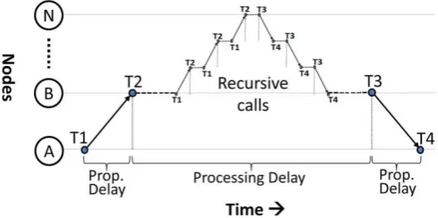
Figure 1. Request and reply mechanism.
The offset and drift compensation is done by the request and reply mechanism, and can be explained using Figure 1. Node A in a multi-hop network sends request at time T1 to the reference node via node B that receives at time T2. The node B, if not a synchronized node, sends this request to another intermediate node in a recursive fashion until it reaches the reference node or a perfectly synchronized node. This reference node or synchronized node then replies back with the timing details that are forwarded to node B through the same path of request. The node B at time T3 forwards this reply message to node A at the time T4. The interval between T2 and T3 does not affect the accuracy of time synchronization [8]. This theory is used to make recursive calls during the interval between T2 and T3 in the RTSP algorithm without the cost of performance. RTSP algorithm does not require any tree-like structure. It works with any network topology, flat and clustered. The whole mechanism can be explained like this; the synchronization request initiated by any node is recursively forward to the reference node via intermediate nodes. The reference node or any node in the requested path then replies with the timing information via same path and hence the requested node becomes synchronized.
ISSN(Online): 2320-9801
ISSN (Print): 2320-9798
I
nternational
J
ournal of
I
nnovative
R
esearch in
C
omputer
and
C
ommunication
E
ngineering
(An ISO 3297: 2007 Certified Organization)
Vol. 3, Issue 9, September 2015
to become synchronized before distant node and any synchronized node on the request path can reply, very few time synchronization requests are forwarded all the way to the reference node.
After start up the nodes send enquiry message to all its neighbours about the identification of reference node, wait for some period, say T or till the reply message is received, run repeatedly the RTSP algorithm that takes care of the dynamic election of a single reference node with the smallest ID. The compensation of offset and drift is as follows.
When a new message is received by a node, it checks whether it is a request.
If yes, it notes the received time T2. If the node is a reference node of synchronized cluster head, it sent back a message containing timing information such as T1, T2, T3, Tr (global time). But if the node is unsynchronized, it recursively forward the message to the reference node. Before forwarding it stores the client ID in myClient and values of T1 and T2 in T1old and T2old.
When the reply message sent by the reference node is received by a node which is in the requested path, performs the following action. It calculates the propagation delay by
𝑑 = 𝑇2 − 𝑇1 + (𝑇4 − 𝑇3) 2
The new Tr can be calculate by adding this d to the received Tr. It then records Tr which is the global time and T4, the local time. On the other hand if the node is an intermediate node, it collect the values of T1 and T2, find the value of Tr by using the equation
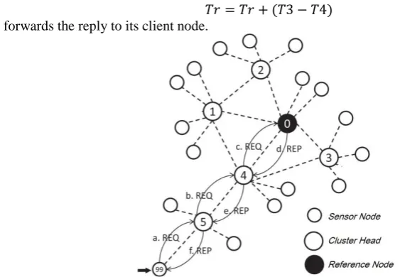
𝑇𝑟 = 𝑇𝑟 + (𝑇3 − 𝑇4)
and forwards the reply to its client node.
Figure 2.An example request and reply mechanism in RTSP algorithm.
ISSN(Online): 2320-9801
ISSN (Print): 2320-9798
I
nternational
J
ournal of
I
nnovative
R
esearch in
C
omputer
and
C
ommunication
E
ngineering
(An ISO 3297: 2007 Certified Organization)
Vol. 3, Issue 9, September 2015
V. PROPOSED SYSTEM
In Recursive Time Synchronization Protocol there is no steps taken for cluster head or link failure. Therefore if a cluster head or link failure occurs in the middle of request reply mechanisms that request won't get any reply and that requested node cannot be synchronized with reference node. I introduce a new algorithm which ensure the connectivity as the main concern and thus avoid re-synchronization. Avoiding re-synchronization reduce energy consumption and thus increase the battery life.
A. Assumptions in the proposed algorithm:
Sensor nodes are provided with unique identification numbers from 0 to n-1 for n nodes. MAC layer time-stamping is possible for each node.
Neighboring nodes can communicate over unreliable, error corrected wireless channel. Broadcasting of messages is possible in the network.
Skew do not change during the short interval between a request and its reply. Propagation delay in one direction is same as in opposite direction.
There exists a simple linear relationship between clocks of two nodes.
B. Time-Stamping:
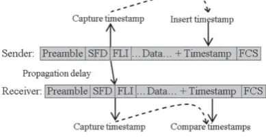
MAC layer time-stamping of messages[8],[14],[15] both at sender and receiver sides, is very useful for time synchronization in sensor networks. The standard IEEE 802.11 MAC frame consist of 4 bytes of preamble, 1 byte SFD, 1 byte of frame length indicator, a maximum of 125 bytes of data and 2 bytes of frame check sequence [16]. Figure 3.shows that the proposed algorithm timestamps the message when an interrupt is generated at the radio chip of the micro controller after a SYNC/SFD byte has been received or sent. This interrupt occurs almost simultaneously both at sender and receiver with a difference of 3𝜇𝑠 if the propagation delay is assumed to be slow. Therefore the timestamp at the sender side is increased by 3𝜇𝑠.
Figure 3.Structure of MAC frame and time-stamping.
This time-stamping approach is more accurate as well as simpler and faster than conventional timestamps in which timestamps are made at the end of each byte after SFD bye, normalized, averaged, error corrected and then final timestamp is embedded in the message field.
C. Structure of the synchronization message:
ISSN(Online): 2320-9801
ISSN (Print): 2320-9798
I
nternational
J
ournal of
I
nnovative
R
esearch in
C
omputer
and
C
ommunication
E
ngineering
(An ISO 3297: 2007 Certified Organization)
Vol. 3, Issue 9, September 2015
D. Election of Reference Node:
The node with highest energy in the whole network is elected as the reference node. If a new message is received it checks the value of reference node ID field and do the following. If the field contains a value which is the ID of the reference node it is broadcasted as follows.
Algorithm 1:Election of Reference Node Check if the new message is received If message →messageType = = enquiry then If(message →referenceNodeEnergy≥ myEnergyand myReference is empty) or
myEnergy< message →referenceNodeEnergythen //accept new reference ID and broadcast
myReference = message →referenceNodeID Else IfmyEnergy>referenceNodeEnergythen myReference = message→myID
//rebroadcast the message End if
End if End if
If the receiving node does not know the ID of reference node or it knows some ID of a node which has lesser energy it updates its reference node ID field with received value and rebroadcast.
If the receiving node energy is higher than the current reference node, it contest for reference node by broadcasting message with its own ID in the reference node ID field.
Compensation of offset and drift, adaptive re-synchronization interval, aggregation of synchronization requests are same as in RTSP protocol. The improvement in previous algorithm is as follows.
E. Election of cluster heads:
In this method, initial cluster head selection process considers the remaining energy of nodes. A group of nodes which are closer to each other are made into clusters. Among those clusters, node with highest energy is selected as cluster heads. Since all the nodes in a cluster exchange message via its cluster head, message transmission in a cluster head will be higher than other nodes. These message exchanges use more power from the battery. Therefore cluster heads needs more power than other nodes in the network. After many message exchanges the energy of cluster head reduces. This results in node or link failure. In order to avoid this problem node with highest energy is elected as cluster heads in the initial time itself.
Algorithm 2: Election of Clusterhead currentNodeID==0
IfcurrentNodeEnergy>ThresholdEnergy message → ClusterheadID
// Broadcast the message
currentNodeID = currentNodeID + 1 End if
F. Compensation for Node Failure:
ISSN(Online): 2320-9801
ISSN (Print): 2320-9798
I
nternational
J
ournal of
I
nnovative
R
esearch in
C
omputer
and
C
ommunication
E
ngineering
(An ISO 3297: 2007 Certified Organization)
Vol. 3, Issue 9, September 2015
Figure 4. Synchronization Request
In the Figure 4.R represent the reference node and S is the source node which initiates the synchronization request. The source, S sent request to reference node, R. Then reference node sent back the reply.Sometimeclusterheadmay fails in the requested path as in the figure 5. If a clusterhead is down all nodes in that cluster will become useless.This Improved algorithm introduces a new cluster head re-election process. Nodes with differentresidual energy may exist in a WSN at any time. If a cluster head energy become low then new cluster head with high energy is re-elected which is illustrated in Figure 6. This new clusterhead is in the same cluster of previous clusterhead.
Figure 5. Node failure in the requested path during reply
When combining with synchronization it becomes bit complicated since the request and reply passes mainly via these clusterheads. This is not just a cluster head selection process, instead if the election process is in the middle of a request reply process then the whole information stored (T1, T2 and ClientID) in old node during request is transferred to the new cluster-head when the old node's energy reduces to a predefined threshold. i.e., after the request processing at the reference node if any of the cluster head in the request path fails reply cannot forward via the same path of request.
Algorithm 3: Compensation for Node Failure currentChID = = 0
IfChEnergy< threshold
//Cluster head reelection in same cluster begins //Checking the energy in the same cluster currentNodeID== 0
ISSN(Online): 2320-9801
ISSN (Print): 2320-9798
I
nternational
J
ournal of
I
nnovative
R
esearch in
C
omputer
and
C
ommunication
E
ngineering
(An ISO 3297: 2007 Certified Organization)
Vol. 3, Issue 9, September 2015
// Send data to newly elected cluster-head // Broadcast the ID of cluster head to its nodes ElseifcurrentNodeID = currentNodeID + 1 Endif
Endif
currentChID = currentChID + 1 Endif
Figure 6.Cluster head re-election
The old algorithm does not consider the connectivity and the current request is dropped and starts a new request via another cluster head. This re-synchronization again increases the energy consumption and thus reduces battery life. In this algorithm the delay is calculated by transferring the data in old node to the newly elected node. The connectivity cannot be neglected in applications such as military and chemical plants where node failure is common. In such cases this algorithm is therefore more efficient than conventional Recursive Time Synchronization Protocol. This algorithm works well in clustered as well as flat network. Here I only consider clustered network. All the nodes must be considered as cluster heads in order to use this algorithm in flat network.
VI.OBSERVATIONS AND EXPERIMENTAL RESULTS
A. Simulation Setup:
Simulation was performed in Network Simulator version 2.35 using the parameters given in Table 1. Note the use of random topology and pause time of zero makes the network highly dynamic. A time synchronization protocol that performs better in such a dynamic network is expected to perform even better in a static environment. The main steps of the simulation are as follows.
1. A class for sensor node is defined with different attributes, such as ID, position (x, y, z), energy level, parent ID, current time, offset (α), and skew (β).
2. A set of network parameters are defined including the total number of nodes in the network, deployment area and re-synchronization interval.
3. For total number of nodes, instances of the sensor node class are created, and random values are generated for the position of each node.
4. Communication links are defined according to the transmission range and distance between sensor nodes. 5. Two instances of the above network are created for the two protocols to run.
6. Protocols are run on their own instance of the network for several times, and results are stored. 7. Data is analyzed for energy consumption.
ISSN(Online): 2320-9801
ISSN (Print): 2320-9798
I
nternational
J
ournal of
I
nnovative
R
esearch in
C
omputer
and
C
ommunication
E
ngineering
(An ISO 3297: 2007 Certified Organization)
Vol. 3, Issue 9, September 2015
Table 1. Simulation Parameters
Parameter Description No. of Nodes 40
Topology Random
Deployment area 1300m x 1300m Channel Wireless
MAC IEEE 802.11
Antenna Omni
Routing Protocol AODV
B. Simulation Results:
The simulation was run to collect data on Energy consumption in the long run. Energy consumption is a very important while considering the performance of time synchronization algorithms. However, actual energy consumption many be affected by many factors, such as antenna used, type of the hardware and software. Therefore, the energy consumption in terms of total number of time synchronization messages exchanged among the nodes is measured by assuming same type of hardware, software, and antenna for all protocols.
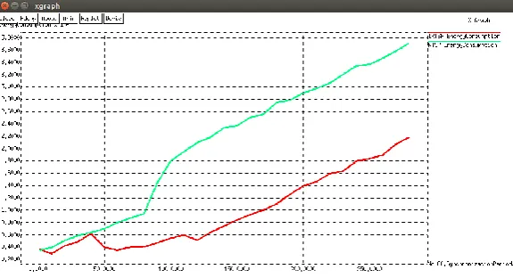
Figure 7.Total energy consumption in the long run (for 40 nodes).
On startup of the network, a node sends two request messages and gets their replies accordingly. However, once the nodes are synchronized, they need to send very less number of requests due to the adaptive behavior of IRTSP algorithm. Also due to node failure compensation resynchronization can be eliminated and thus can reduce the number of messages exchanged for synchronization. To find the total number of messages sent in IRTSP in the long run, data is collected from simulation of a network of 40 nodes for very long time.Using the XGraph in NS2, the graph which compares the two algorithms is plotted.Figure 7.shows that, in the beginning, total energy consumption (i.e., no. of messages exchanged) of the IRTSP algorithm is approximately equal to RTSP.It then remains always lower than the RTSP protocol in the long run.
VII. CONCLUSION
ISSN(Online): 2320-9801
ISSN (Print): 2320-9798
I
nternational
J
ournal of
I
nnovative
R
esearch in
C
omputer
and
C
ommunication
E
ngineering
(An ISO 3297: 2007 Certified Organization)
Vol. 3, Issue 9, September 2015
REFERENCES
1. Muhammad Akhlaq, and Tarek R. Sheltami, “RTSP: An Accurate and Energy-Effcient Protocol for Clock Synchronization in WSNs", IEEE Transactions on Instrumentationand Measurement, vol. 62, no. 3, March 2013.
2. Anastasi, M Conti, M Di Francesco, and A Passarella, “Energy Conservation in Wireless Sensor Networks: A Survey", Ad Hoc Netw., vol.7.no3, pp.537-568, May 2009.
3. C. Dunn, D. Jeerson, S. Lichten, J. Thomas, Y. Vigue, and L. Young, “Time andPosition Accuracy using Codeless GPS", in Proc. 25th PTTI Conf., Marina Del Rey, CA, 1993, pp. 169-179.
4. D. L. Mills, “Internet Time Synchronization: The Network Time Protocol", IEEE Trans.Commun., vol. 39, no. 10, pp. 82{1493, Oct. 1991.
5. “IEEE Standard for a Precision Clock Synchronization Protocol for Networked Measurement and Control Systems", IEEE Std.
1588-2008, 1588-2008, pp. c1-269, (Revision of IEEEStd. 1588-2002).
6. J. Elson, L. Girod, and D. Estrin, “Fine-Grained Network Time Synchronization using Reference Broadcasts”, ACM SIGOPS Oper. Syst. Rev., vol. 36, no. SI, pp. 147-163, Winter 2002.
7. SaravanosYanos, “Energy-Aware Time Synchronization in Wireless Sensor Networks", Technical report, Department of Computer Science, University of North Texas,December 2006.
8. S. Ganeriwal, R. Kumar, and M. B. Srivastava, “Timing-Sync Protocol for Sensor Networks", in Proc. 1st Int. Conf. SenSys, 2003, pp. 138-149.
9. M. Maroti, B. Kusy, G. Simon, and A. Ledeczi, “The Flooding Time Synchronization Protocol", in Proc. 2nd Int. Conf.SenSys, New York, 2004, pp. 39-49..
10. Ali BurakKulakli, “Time Synchronization in Wireless Sensor Networks", Master Thesis, Izmir Institute of Technology, Computer Science, Izmir, Turkey, 2008.
11. Ali BurakKulakli, KayhanErciyes, “Time Synchronization Algorithms Based on Timing-Sync Protocol in Wireless Sensor Networks", 23rd
International Symposium on Computer and Information Sciences, 2008.
12. H. Kopetz and W. Schwabl, “Global Time in Distributed Real-Time Systems", TechnicalReport 15/89, TechnischeUniversitat Wien, 1989. 13. Shujuan Chen, Adam Dunkels, Fredrik Osterlind, Thiemo Voigt and Mikael Johansson, “Time Synchronization in Predictable and Secure
Data Collection in Wireless Sensor Networks", in Proc. 6th Med-Hoc-Net 2007, Corfu, Greece, 2007.
14. D. Cox, E. Jovanov, and A. Milenkovic, “Time Synchronization for Zig- Bee Networks",in Proc. 37th SSST, 2005, pp. 135-138.
15. M. Aoun, A.Schoofs, and P. van der Stok, “Effcient Time Synchronization for Wireless Sensor Networks in an Industrial Setting", in Proc. 6th ACM Conf. SenSys, New York, NY, 2008, pp. 419-420.
16. “IEEE Standard for Information Technology Part 15.4: Wireless Medium Access Control (MAC) and Physical Layer (PHY)
Specifications for Low- Rate Wireless Personal Area Networks (LR-WPANs)", IEEE Std. 802.15.4- 2003, 2003, pp. 1-670.
BIOGRAPHY
Alina John, M. Tech Student, Department of Electronics and Communication Engineering, AmalJyothi College of engineering, Kanjirappally, Kerala, India.