Crosstalk Improvement of Array Waveguide
Grating Based on Different Channels (64)
Spacing
Salah Elrofai
1and AbdeenAbdelkareem
2Assistant Professor, School of Electronic, Collage of Engineering, Sudan University of Science and Technology,Sudan, Department of Electrical, Collage of Engineering, AL-Baha University, AL-Baha, Saudi Arabia1.
Full Professor, School of Electronic, Collage of Engineering, Sudan University of Science and Technology, Sudan2.
ABSTRACT: This paperintroducedthe cascading configurations of thelarge scale AWGs filters in the
multiplexer/demultiplexerbased on different channels spacing designs under usages of the power full software named WDM_ Phasar simulation. The cascade connectionimproved its capability in solving the accumulated crosstalk problemin AWGwhich it becomes the major limiting factor in the sensitivity of the array in long distance DWDM optical communication link.Acceptableresults are obtained of AWGs filters with cascaded connectionafterusing differentchannels spacing designs of 64 channels (0.708nm, 0.925nm, and 1.233nm). First computed the most significant results of all input information and thenrunning the simulation resulted in the graphical displays of the output power from which the corresponding channels crosstalk are obtained.
KEYWORDS:Accumulated Crosstalk,Array Waveguide Grating, Multiplexer /Demultiplexer, WDM_ Phasar, Dens
Wavelength Division Multiplexer.
I.INTRODUCTION
ISSN(Online): 2320-9801
ISSN (Print): 2320-9798
I
nternational
J
ournal of
I
nnovative
R
esearch in
C
omputer
and
C
ommunication
E
ngineering
(An ISO 3297: 2007 Certified Organization)
Vol. 3, Issue 4, April 2015
[9].WDM simulation package is used to speed up the design process, reduce the fabrication runs and device costs. WDM-phasar is a powerful advanced software simulation used for design and modeling Phased Array Grating devices. It provides a number of calculation tools to estimate the device performance before running advanced simulations and fabrication. It is also automates index simulations, estimates quickly the bend loss and crosstalk level, and performs an advanced simulation of the whole device using the beam propagation method (BPM). WDM_ phasar monitors effectively crosstalk level, bend losses, phasar order, dispersion, free spectral range, channel nonuniformity, channel spacing, output channel bandwidth, and diffraction loss. Moreover it also performs other huge variety of important tasks like effective index calculation, design of a WDM device, editing of the WDM device geometry, fast evaluation of the WDM device performance, performing a parameter scan, and run advanced calculations [10].
II. RELATEDWORK
Authors using PLC technology for connect an AWG1 to AWG2, resulting in reducing the circuit size and total channel crosstalk in[11]. Reducing total adjacent crosstalk and accumulated total channel crosstalk values ranging from 32 to -25 dB are achieved by cascading a very large channel-count arrayed waveguide grating filter of 1-THz-spaced channels. This large scale AWG is considered as a primary or first stage of cascading, and it functions as a demultiplexer of ten output bandpass this introduces by authors in [10].Another example of cascading two stages of AWGs as a solution to the problem of crosstalk accumulation in large-scale AWG multiplexers and demultiplexers is that of cascaded AWG module resulting in a very low background crosstalk (nonadjacent crosstalk),This technique involves optimizing the bandwidth of the bandpass stage (second stage) AWG by estimating the spectral characteristics of the whole cascaded AWG as a function of its bandwidth and its center wavelength difference. Using a Gaussian spectral profile for assumed the transmittance in linear unit [12]. More related works in[13– 14] in which the authors using WDM_phasor for designing 8channel, 16channels, and 32 channels with different channels spacing which conclude that the cascade connection is an attractive methods for improve the AWG accumulated crosstalk.
III. RUNNING ADVANCED SIMULATIONS
Using WDM_Phasar simulator to perform a huge variety of tasks as to do effective index calculations, to design a WDM device, to edit the WDM Device geometry, to use the tools for fast evaluation of the WDM device performance, to perform parameter scan, and to run advanced calculations.Firstopen a new project, then define the parameters for the layers of a multilayer ridge waveguide, and enter data for each layer. Second complete the set of calculation parameters by editing the waveguide width,the wavelength, the number of points in mesh, and the polarization (TE or TM). Third perform effective index simulations of the waveguide designed.The data from the effective index simulation can be used directly in the WDM design as default parameters for the wafer and the waveguide. Fourth find the modal indices of all the modes supported by the guiding structure and display the modal field distribution and the refractive index distribution as shown inthefig.1.
Fig.1. Modal field and refractive index distribution
Fig.2.Effective index of the input waveguides
On the Phased Array Section of the input and output coupler,edit the following parameters:the radius of the output surface to the Free Propagation Region, the number of the waveguides, the separation from waveguide center to next waveguide center, the width of the waveguide, the real and the imaginary values, the tapered start and end width and the length of the tapers then access the parameters of the Phased Array Section and editthe real and the imaginary values, the number of the waveguides, the width of the waveguide,the length increment with respect to the previous path, the difference between the distance span of the path and the length along the path fig.3 show that. All The previous procedures has been done fortheeffective index ofan outputwaveguides that shown in fig.4.
Fig.3.Input and output coupler of PAS section
Fig.4.Effective index of the output waveguides
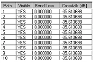
Then access the statistics information regarding the Phased Array, the Input Array, and the Output Array.WDM Phasar recalculates the exact maximum Cross-talk level that corresponds to a given minimum separation distance, table (1) show that.
Table (1) PA satistics information
ISSN(Online): 2320-9801
ISSN (Print): 2320-9798
I
nternational
J
ournal of
I
nnovative
R
esearch in
C
omputer
and
C
ommunication
E
ngineering
(An ISO 3297: 2007 Certified Organization)
Vol. 3, Issue 4, April 2015
amplitude (in dB), width, spacing, and cross-talk level for all designed channels are obtained after choosing statistics from the menu.
IV. WDM_PHASAR SIMULATOR-BASED AWGUNITS DESIGN
Now WDM_ Phasar simulator is used for designing 64-channels unit as DWDM multiplexers/Demultiplexerswith different channel spacing. The simulation is run for design unit to obtain the crosstalk of each channel. Then the simulation is run in cascading manner by activating the cascading tool for design unit, and at the end of the scanning the simulator provides the resulting crosstalk [14].
V. DESIGN OF 64 CHANNELS WITH DIFFERENT CHANNEL SPACING
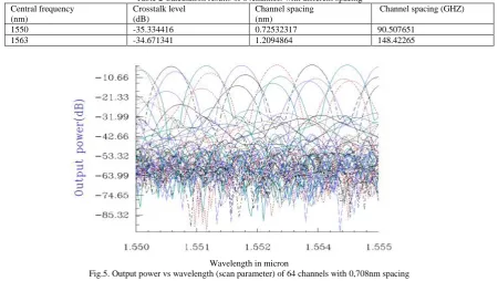
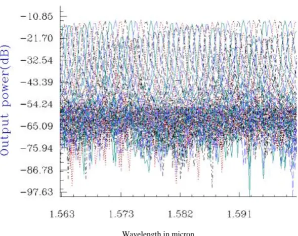
The same design procedures and simulations are once more repeated for 64 channels. The calculated results are obtained in table (2), which indicates thatthe results before simulation are perfect for the next step.Running the simulation for the 64 channels with different channel spacing (0.708nm, 0.925nm,1.233nm) gave the graphical display of the output power, and summaries of the corresponding device performance, shown in the figures (5, 6 )and in the tables (3, 4, 5).
Table 2 Calculation results of 64channels with different spacing Central frequency
(nm)
Crosstalk level (dB)
Channel spacing (nm)
Channel spacing (GHZ)
1550 -35.334416 0.72532317 90.507651
1563 -34.671341 1.2094864 148.42265
Wavelength in micron
Fig.5. Output power vs wavelength (scan parameter) of 64 channels with 0,708nm spacing
Table 3 AWG results of simulation of some of the 64 channels (0.708nm).
Channel Amplitude
In dBs
Channel spacing ( nm) Crosstalk In dBs
5 -31.093124 0.708 -37.629554
8 -26.926296 0.708 -35.607433
18 -12.355805 0708 -36.814044
34 -3.987291 0.750 -32.047409
45 -10.308849 0.708 -34.894328
47 -12.570023 0.708 -35.834738
50 -16.599511 0.708 -36.941179
Wavelength in micron
Fig.6. Output power vs wavelength (scan parameter) of 64 channels with 0.925nm spacing
Table 4 AWG results of simulation of some of the 64 channels with 0.925nm spacing.
Channel Amplitude In dBs
Channel spacing ( nm)
Crosstalk In dBs 16 -14.651668 0.925 -35.571313 20 -14.354681 0.925 -35.421206 29 -12.608559 0.925 -34.228998 33 -13.274888 0.925 -33.504044 45 -16.899037 0.925 -32.070064 49 -18.551693 0.925 -31.249453 52 -20.399761 0.925 -32.263407 61 -27.711344 0.925 -33.333303
Table 5 AWG results of simulation of some of the 64 channels with 1.233nm spacing.
Channel Amplitude In dBs
Channel spacing ( nm)
Crosstalk In dBs 8 -32.764409 1.233 -32.348377 10 -31.654053 1.233 -31.310917 16 -28.794602 1.233 -28.629350 20 -27.622909 1.233 -27.591520 30 -26.207143 1.233 -26.419111 32 -26.214887 1.233 -26.413136 48 -29.951886 1.233 -30.622390 52 -31.827966 1.233 -31.903305
ISSN(Online): 2320-9801
ISSN (Print): 2320-9798
I
nternational
J
ournal of
I
nnovative
R
esearch in
C
omputer
and
C
ommunication
E
ngineering
(An ISO 3297: 2007 Certified Organization)
Vol. 3, Issue 4, April 2015
VI. CONCLUSION
The series connection or cascading connection of large scale AWGs is a power full method for reducing the transmittance that results in acceptable reduction of accumulated crosstalk of multiplexers/demultiplexers based on DWDM. Running WDM_sumulaor for 64 channels under different channels spacing achieves a reasonable crosstalk which improve the long distance communication with more channel caring capacity.
REFERENCES
1. HDBK, M., “Design Handbook for Fiber optic communication systems,” 415A17 October 1994. 2. Krauss, O., “DWDM and optical Networks”, (c) 200 by publicscommunications agency.
3. Elmirghani, J. M.H., “All-optical wavelength conversion: Technologies and applications in DWDM Networks”, IEEE communication, Magazine march 2000.
4. EXFO Electro-optical Inc.., Quebec. Canada, 2nd edition.
5. Okamoto. K.H.Y. Okazaki .Y.Ohmori. Kato. K., “Fabrication of large scaleintegrated-optic NxN star couplers,” IEEE photonics Tech. Lett.4:1032-1035,1992
Hibino, Y., “Recent Advance in high-Density and large-scale AWG Multi/Demultiplexers with higher Index-Contrast Silica-based PLCs” IEEE Journal of selected Topics in Quantum Electronics vol. 8, No. 6November/ December 2002.
6. Chin, K. S., Yang, K., Zhang, X., Hung Lu, L., Katehi, L. P. B., and Bhattacharya,P. “Investigation of Adjacent Channel Crosstalk inMultichannel Monolithically Integrated 1550nm Photoreceiver Arrays”, Journal of Lightwave Technology, VOL.. 15, No. 10, October 1997. 7. Kaneko, A., “Recent Progress on Arrayed-Waveguide Grating for WDM Applications”, NTT Photonics Laporatories, 7803-5633-1/99/$10.00 © 1999 IEEE.
8. Kawia, T., and Obara, H., “Crosstalk reduction in NxN WDM Multu/Demultiplexers by cascading small Array Waveguide Gratings”, G‟s,‟ Journal of lightwave Technology, Vol…15, No. 10, October 1997.
9. WDM_Phasar, „Phased Array WDM Device Design Software‟, Optiwave Corporation, 16 Concourse Gate, Suite 100 Nepean, Ontario K2E 7S8, 1998.
10. Kamei, M. Ishii, M., Kitagawa, T.,Itoh, M., and Hibino,Y., “64-channel ultra-low crosstalk arrayed-waveguide grating multi/Demultiplexer module usingcascade connection technique, ” Electronics letters 9th January 2003VOL. 39 NO. 1.
11. Takada, K., Abe, M., Shibata, T., and Okamoto, K., “10-GHz-Spaced 1010-Channel Tandem AWG Filter Consisting of One Primary and Ten Secondary AWGs,” IEEE Photonics Technology Letters, VOL..13,NO. 6, June 2001.
12. Kamei, S., Kaneko,A.,Ishii, M.,Shibata, T., Inoue, Y., and Hibino, Y., “Crosstalk reduction in arrayed-waveguide grating multiplexer/demultiplexer using cascade connection,” Journal of lightwave technology, VOL..23, No. 5,May 2005.
13. SALAH, E., andAbdeen, A.,“Crosstalk Reduction using Cascade Connections of Multiplexer/Demultiplexer with different Channels (8&16) Spacing Based Array Waveguide Grating in Dense Wavelength Division Multiplexing”,IJISET - International Journal of Innovative Science, Engineering & Technology, Vol. 1 Issue 10, December 2014.
14. SALAH, E., andAbdeen., “Accumulated Crosstalk Enhancement of Array waveguide Grating With different Channels (32) Spacing”,IJIRCCE- International Journal of Innovative Research in Computer and Communication Engineering, Vol. 3, Issue 2,Febrory 2015.
BIOGRAPHY
Salah ElfakiElrofai, Ph.D., Sudan University of Science and Technology, College of Engineering, School of