Behaviour of Steel Frame Structure under
Dynamic Loading
Bharath K1, D Datta2
P.G. Student, Department of Applied Mechanics, Visvesvaraya National Institute of Technology, Nagpur,
Maharashtra, India1
Assistant Professor, Department of Applied Mechanics, Visvesvaraya National Institute of Technology, Nagpur,
Maharashtra, India2
ABSTRACT: A research aims to study the behaviour of gable stay steel frame structures designed as per Indian codes under strong ground motions and dynamic wind load. For this a nonlinear time history analysis of the gable stay steel frame structureunder various ground motions are carried using SAP2000 software.It is assumed that the structure is located at various regions of India and behaviour of those structures are compared. It is observed that storey drift of structure located under seismic zone III and below will be in the permissible limit and requires simple bracings but the structure located in seismic zoneV will exceeds the limit and Indian seismic code for design of steel structures are not enough to satisfy the design requirements.
KEYWORDS:Gable stay steel frame, Time history analysis, and Ground motions.
I. INTRODUCTION
Earthquake are perhaps the most unpredictable and devastating of all natural disasters. They not only cause great destruction in terms of human casualties, but also have a tremendous economic impact on the affected area. Earthquake creates vibration on the ground that are translated into dynamic loads which causes the ground and anything attached to it to vibrate in a complex manner and cause damage to buildings and other structures. According to the recent Indian standard code on earthquake resistant design of structure more than 60-65% of the area of our country falls under seismic zone III and above. This underlines the importance of seismic detailing. For Indian site condition sever earthquakes have an extremely low probability of occurrence during the life of a structure. If a structure has to resist such earthquake elastically, it would require an expansive lateral load resisting system. So Indian seismic design code is for, “To ensure elastic behavior under a moderate earthquake which has a return period equal to the life of the structure and prevent collapse under the extreme probable earthquake.”
Wind speeds vary randomly both in time and space and hence assessment of wind loads and response predictions are very important in the design of several buildings and structures. A large majority of structures met with in practice do not however, suffer wind induced oscillations and generally do not require to be examined for the dynamic effects of wind. For such normal, short and heavy structures, estimation of loads using static wind analysis has proved to be satisfactory. The details of this method involving important wind characteristics such as the basic wind speeds, terrain categories, modification factors, wind pressure and force coefficients, etc. Wind is air in motion relative to the surface often earth. The primary cause of wind is traced to earth's rotation and differences in terrestrial radiation. The radiation effects are primarily responsible for convection either upwards or downwards.
beam moment and corresponding shear expected during strong seismic shaking when plastic hinges are formed in the beam. These two requirements are in the line with the strong column weak beam philosophy and use the capacity design concept.
The recent version of the code IS 800-2007 contains provision for design and detailing for seismic loads, but it does not suggest the type of connections which are suitable for high or intermediate seismic zones. The American institute of steel construction (AISC) has stipulated that connections in moment resisting frame should be qualified for use by testing. However, as testing of connection is time consuming and expensive, it has also specified a few pre-qualified connections which have been found to be satisfactory (FEMA 355D). These connections may be adopted in India also for better performance in strong or intermediate Earthquake.
Nonlinear time history analysis is an important technique for structural seismic analysis especially when the evaluated structural response is nonlinear. To perform such an analysis, a representative earthquake time history is required for a structure being evaluated. Time history analysis is a step by step analysis of the dynamic response of a structure to a specified loading that may vary with time. Time history analysis is used to determine the seismic response of a structure under dynamic loading of representative earthquake.
II. RELATED WORK
Wang and Wen (1994), investigate the “Evaluation of pre-Northridge low-rise steel buildings I: modeling.” Author developed a smooth connection-fracture hysteresis model, to account for the effects of flexible floor systems, biaxial interaction, and torsional motion, a 3D inelastic structural analysis 2 story model is used. Once connection fracture results in complete structural member failures, the response would increase drastically that collapse might occur. Therefore, it is concluded that fractured connections with some residual strength, even as low as 30% of the original, may act as energy dissipaters and have mitigating effects in structural response. On the other hand, once connecting fracture results in complete beam failures, the response is amplified considerably. It is also shown that total column failure further increases the maximum response and permanent displacement, confirming the expectation that column failure can cause collapse.
Dhande, et al., (2000), presented the paper on “Industrial building design on seismic issues.” They researched to propose simple but innovative and effective lateral load resisting structural system (LLRSS) or structural technology and methodology for the seismic control which can be used in new as well as old structures. The author generated industrial building with braced frame model using SAP 2000; and analyzed with a SRSS method. The lateral load used for the analysis are Earthquake motion of Bhuj Earthquake as per IS1893-2002. They concluded that time period for braced frame will be less compered to unbraced frames. Braced model reduces the roof displacement significantly as compared to unbraced model. It also reduces the axial force, shear force, and bending moment in the column significantly compared to unbraced model.
Paul, et al. (2000), had made a review on the “State of the art review on seismic design of steel moment resisting frames part II: strength and drift criteria.” The author explained about the seismic design provision related to strength and drift criteria as given in American and Indian code.American code adopted the strong column weak beam concept of frame design which is important in ensuring ductile behavior of the frame. The Indian code have no such specification. In American codes clear guidelines are available regarding the importance of including joint deformation is estimating the drift of a moment resisting frame.so drift estimation procedure must be clearly outlined in the Indian code.
III. EXPERIMENTAL RESULTS
At present study behavior of 3D single bay industrial steel structure under strong ground motion located at various regions of India is investigated.The dimensions of the gable stay steel frame adopted for the nonlinear analysis is shown in Fig 1 and Table 1.The location of the structure assumed for the research are as follows,
Darbhanga, Bihar which comes under the seismic zone V as per IS1893 (part 1): 2016 and wind zone VI as per IS875 (part 3): 2015.
Fig 1. 2DGable stay frame model
Table 1. The general description of steel structures
Length 30m
Breadth 12m
Height of frame 11m
Number of frames 6nos
Yield strength of steel 250mpa
Grid to grid spacing in X direction 6m Grid to grid spacing in Y direction 6m
The east coast and Gujrat on west coast of India is relatively more vulnerable for occurrences of cyclones. The structures located in this region are severely affected by the wind force. As per literature the wind loads are predominant while design of the members of steel structure sothe coefficients used for the calculation of wind load acting on the structure located at both the regions are shown in table 2. The Indian site condition are experienced with an extreme earthquake having a magnitude of 7 and above. The earthquake causes both vertical and horizontal vibration to the structure. Though it as less effect on the individual members of steel frame but it leads to total storey drift of structure.This necessitate the seismic design of structure and the coefficients used for calculation of seismic load are shown in table 3. The final loads acting on the frame calculated based on location are shown in table 4.
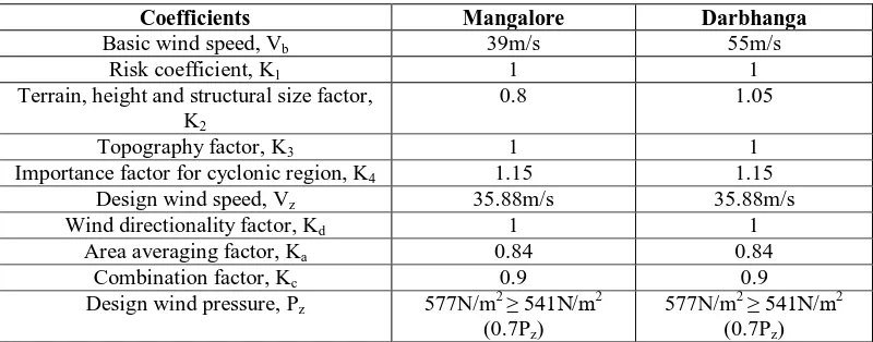
Table 2. Wind coefficients [IS875 (Part 3): 2015]
Coefficients Mangalore Darbhanga
Basic wind speed, Vb 39m/s 55m/s
Risk coefficient, K1 1 1
Terrain, height and structural size factor, K2
0.8 1.05
Topography factor, K3 1 1
Importance factor for cyclonic region, K4 1.15 1.15
Design wind speed, Vz 35.88m/s 35.88m/s
Wind directionality factor, Kd 1 1
Area averaging factor, Ka 0.84 0.84
Combination factor, Kc 0.9 0.9
Design wind pressure, Pz 577N/m2 ≥ 541N/m2 (0.7Pz)
Table 3. Seismic coefficients [IS1893 (Part 1): 2016]
Table 4.Loads acting on the frame structure
Coefficients Mangalore Darbhanga
Dead load [IS875 (Part1): 1987] 0.27kN/m2 0.27kN/m2 Imposed load [IS875 (Part2): 1987] 0.59kN/m2 0.59kN/m2 Wind load on Roof [IS875 (Part3): 2015] 0.75kN/m2 1.664kN/m2 Wind load on Column [IS875 (Part3): 2015] 0.70kN/m2 1.56kN/m2
Seismic load [IS1893 (Part1): 2016] 3.19kN/m2 5.21kN
Model – 1
The mathematical model of 2D gable stay frame is generated in SAP2000 software as shown in Fig 2. The load acting on the frame were assigned and model is analyzed for different load combination. The maximum moments, shear force and axial load diagrams obtained for different load combinations for individual members were noted and are shown in Table 5. The individual members were designed for the maximum moments, shear force and axial load and checked for deflection as per IS800: 2007. The final sizes of the members were shown in Table 6.
Fig 2. 2D gable stay steel frame SAP model
Coefficients Mangalore Darbhanga
Zone factor, Z 0.16 0.36
Importance factor, I 1.2 1.2
Response reduction factor, R 3 3
Soil type II medium stiff soil II medium stiff soil
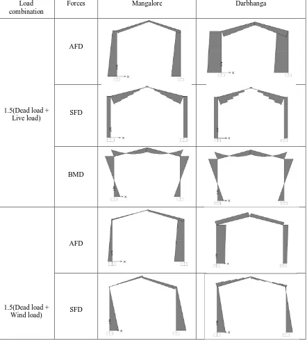
Table 5. Axial force, shear force and bending moment diagrams under various load combinations
Load combination
Forces Mangalore Darbhanga
1.5(Dead load + Live load)
AFD
SFD
BMD
1.5(Dead load + Wind load)
AFD
BMD
Table 6. Sectional properties of steel frame
Member Mangalore Darbhanga
Purlin and Runner ISMC150 ISMC150
Beam ISMB250 ISMB400
Column ISMB400 ISMB550
Model - 2
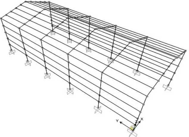
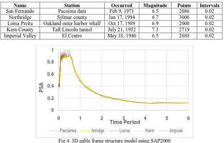
The 3D mathematical model of gable stay frame structure isgenerated in SAP2000 as shown in fig 3. The loads acting on the structure are defined and assigned to an individual members. The nonlinear time history analysis of an industrial steel frame is carried out under ground motions as mentioned in table 7.The plastic hinges are generated for column and beam member of a mathematical model as per ASCE 41-13.The ground motions are scaled as per spectral matching using time domine for peak ground acceleration of specific zone. The graph showing scaled pseudo spectral acceleration is shown in fig 4.
Table 7. Ground motions used for nonlinear time history analysis
Name Station Occurred Magnitude Points Intervals
San Fernando Pacoima dam Feb 9, 1971 6.5 2086 0.02
Northridge Sylmar county Jan 17, 1994 6.7 3000 0.02
Loma Preita Oakland outer harbor whalf Oct 17, 1989 6.9 2000 0.02 Kern County Taft Lincoln tunnel July 21, 1952 7.3 2719 0.02
Imperial Valley El Centro May 18, 1940 6.5 2688 0.02
Fig 4. 3D gable frame structure model using SAP2000
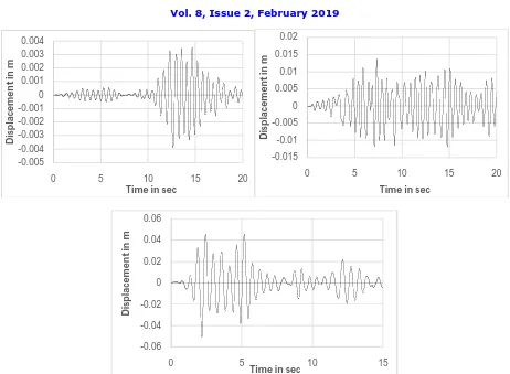
After the nonlinear time history analysis of the 3D frame structure under the various scaled ground motions the displacement of the structure along lateral directions with respect to time at joint of column J-1 is extracted, a graph is plotted against displacement in m vs time period in sec for the structure located in Mangalore and Darbhanga region as shown in Fig 5 & 6 respectively.
0 0.2 0.4 0.6 0.8 1
0 1 2 3 4 5 6
P
SA
Time Period
Pacoima Nridge Loma Kern Impval
-0.05 -0.04 -0.03 -0.02 -0.01 0 0.01 0.02 0.03 0.04 0.05
0 5 10 15
D
isp
la
ce
m
e
n
t
in
m
Time in sec
-0.004 -0.003 -0.002 -0.001 0 0.001 0.002 0.003 0.004
0 5 10 15
D
is
p
la
ce
m
e
n
t
in
m
Fig 5. Displacement of gable frame structure located at Mangalore along lateral direction -0.002 -0.0015 -0.001 -0.0005 0 0.0005 0.001 0.0015 0.002
0 10 20
D
is
p
la
ce
m
e
n
t
in
m
Time in sec
-0.006 -0.004 -0.002 0 0.002 0.004 0.006 0.008
0 5 10 15 20
D
isp
la
ce
m
en
t
in
m
Time in sec
-0.03 -0.025 -0.02 -0.015 -0.01 -0.005 0 0.005 0.01 0.015 0.02 0.025
0 5 10 15
D
is
p
la
ce
m
e
n
t
in
m
Time in sec
-0.12 -0.1 -0.08 -0.06 -0.04 -0.02 0 0.02 0.04 0.06 0.08 0.1
0 5 10 15
D is p la ce m e n t in m
Time in sec
-0.01 -0.008 -0.006 -0.004 -0.002 0 0.002 0.004 0.006 0.008
0 5 10 15
D is p la ce m e n t in m
Fig 6. Displacement of gable frame structure located at Darbhanga along lateral direction
The displacement response spectra curve is generated by considering 5% damping at column joint J-1 for gable stay frame structure located at Mangalore and Darbhanga regions along lateral direction as shown in Fig 7& 8 respectively.
Fig 7. Displacement response spectra curve under 5% damping for structure at Mangalore region -0.005 -0.004 -0.003 -0.002 -0.001 0 0.001 0.002 0.003 0.004
0 5 10 15 20
D is p la ce m e n t in m
Time in sec
-0.015 -0.01 -0.005 0 0.005 0.01 0.015 0.02
0 5 10 15 20
D is p la ce m e n t in m
Time in sec
-0.06 -0.04 -0.02 0 0.02 0.04 0.06
0 5 10 15
D is p la ce m e n t in m
Time in sec
0.00E+00 5.00E-02 1.00E-01 1.50E-01 2.00E-01 2.50E-01
0 0.5 1 1.5
S
D
T
Fig 8. Displacement response spectra curve under 5% damping for structure at Darbhanga region
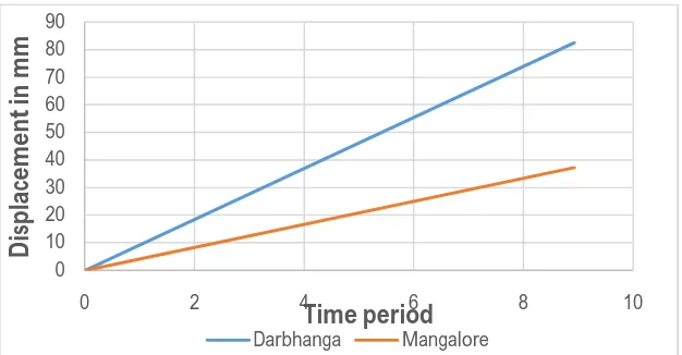
As per IS 1893(part 1): 2016 the maximum permissible storey drift in any storey shall not exceed 0.004 times the storey height i.e. 0.004H = 36mm. The max displacement of structure located in Mangalore region along transvers direction due to earthquake load is 8.7mmand due to wind load is 30.74mm and along lateral direction due to earthquake load is 37.18mm. The max displacement of structure located in Darbhanga region along transvers direction due to earthquake load is 18.87mm and due to wind load is 35.7mm and along lateral direction due to earthquake load is 83.57mm. For both the location displacement due to wind load along lateral direction is negligible. The maximum displacement of structure located at both regions at equal time period is shown in fig 9.
Fig 9. Maximum displacement of structure for both the regions
IV. CONCLUSION
Wind load combination is critical while designing the members of steel structures irrespective of highest wind zone or highest seismic zone depending upon location of the structure.
The structure located up to wind zone III do not require any bracing whereas structure located in wind zone VI requires plan bracings.
The structure located up to seismic zone III requires a simple bracings along lateral direction and clauses of IS codes will satisfy the design requirements whereas structure located in seismic zone V requires special type of bracing system and only IS code is not enough for the design the structure.
0.00E+00 1.00E-01 2.00E-01 3.00E-01 4.00E-01 5.00E-01
0 0.5 1 1.5
S
D
T
Pacoima Nridge Loma Kern Impval
0 10 20 30 40 50 60 70 80 90
0 2 4 6 8 10
D
isp
la
ce
m
e
n
t
in
m
m
Time period
REFFERENCES
[1] A. Gupta, & H. Krawinkler, “Seismic demands for performance evaluation of steel moment resisting frame structures.” Report No. 132: John A Blume earthquake engineering center, Depatment of civil and environmental engineering, Stanford University, Stanford, C.A, (1998). [2] AISC AS. Plastic Design Specifications for Structural Steel Buildings. American Institute of Steel Construction. 1989.
[3] D. P. O'Sullivan, J. F. Hajjar,& R. T. Leon, “Repairs to mid-rise steel frame damaged in Northridge earthquake.” Journal of performance of constructed facilities, 12(4), 213-220, 1998.
[4] E. Reis,& D. Bonowitz, “State of the Art Report on Past Performance of Steel Moment‐Frame Buildings in Earthquakes.” SAC Rep. No. FEMA 355E, Federal Emergency Management Agency, Washington, DC, 2000.
[5] FEMA350, “Recommended Seismic Design Criteria for New Steel Moment-frame Buildings.” Federal Emergency Management Agency. Washington, DC, 2013.
[6] IS 1893. (Part 1), “Criteria for earthquake resistant design of structures, Part I general provision and buildings” (sixth revision). BIS, New Delhi, India, 2016.
[7] IS 1893. (Part 4), “Criteria for earthquake resistant design of structures, Part IV Industrial structures including stack line structures”. BIS, New Delhi, India, 2005.
[8] IS 800, “General construction in steel- code of practice” (third revision). BIS, New Delhi, India, 2007.
[9] IS 808, “Dimensions for hot rolled steel beam, column, channel and angle sections.” BIS, New Delhi, India, 1989.
[10] J. F. Hajjar, B. C. Gourley, D. P. O'Sullivan, & R. T. Leon, “Analysis of mid-rise steel frame damaged in Northridge earthquake.” Journal of performance of constructed facilities, 12(4), 221-231, 1998.
[11] R. Englekirk, “Steel structures: Controlling behavior through design.” Published by John Wiley & sons, INC. New York, USA, (1994). [12] S. A. Mahin, “Lessons from damage to steel buildings during the Northridge earthquake.” Engineering structures, 20(4-6), 261-270, 1998. [13] S. A. Mahin, R. O. Hamburger, & J. O. Malley, “National program to improve seismic performance of steel frame buildings.” Journal of
performance of constructed facilities, 12(4), 172-179, 1998.
[14] S. K. Kunnath,& J. O. Malley, “Advances in seismic design and evaluation of steel moment frames: recent findings from FEMA/SAC Phase II Project.” Journal of Structural Engineering, 128(4), 415-419, 2002.
[15] S. N. Dhande, Y. R. Suryawanshi, & P. S. Patil, “Industrial Building Design on Seismic Issues.” Journal of innovative research in science, engineering and technology, vol. 4, no. 5, pp. 2840-2856, 2015.
![Table 3. Seismic coefficients [IS1893 (Part 1): 2016]](https://thumb-us.123doks.com/thumbv2/123dok_us/1558650.1191421/4.595.188.404.505.614/table-seismic-coefficients-is-part.webp)