Enriched Visual System for Pilot by Using
Head Mounted Display
Sasi Theresa.J1, Sathyavani.M2, Roja.K3 and David William Raj.L4
UG Scholar, Department of ECE, Adhiyamaan College of Engineering, Hosur, TN, India1,2,3
Assistant Professor, Department of ECE, Adhiyamaan College of Engineering, Hosur, TN, India4
ABSTRACT: As the key source of information for pilots , the human visual system has necessarily driven much of the evolution in cockpit technology . In contrast to complicated , gauge-based systems of the past , the electronic flight displays of today’s modern airliners are testament to advances in human factors engineering. The next step in flight instrumentation, although already used for 50 years in military, is just the beginning to emerge in civil transport aircraft. Head mounted displays (HMDs) allow pilots to see key flight instrumentation while viewing the outside world. The need to look down at the flight instruments is removed by the HUD, resulting in increased situational awareness and greater precision in aircraft control. While the head-up display is a welcome development, as with many instances use of human-technology.
KEYWORDS: CGI, 3D Format, IMC, infrared sensing, acoustic, thermographic sensor,HMIT
I. INTRODUCTION
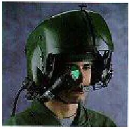
A helmet – mounted display (HMD) is a devices used in aircraft to project information to the pilot’s eyes. Its scope is similar to that of head-up displays (HUD) on an aircrew’s visor or reticle. An HMD provides the pilot with situation awareness, an enhanced image of the scence, and in military applications cue weapons systems, to the directions their head is pointing. Application which allow cuing of weapon systems are referred to as helmet-mounted sight and display (HMSD) or helmet-mounted sights (HMD).
II. HISTORY
helmet that was flown in the 1974–78 ACEVAL/AIMVAL on U.S. F-14 and F-15 fightersVTAS received praisefor its effectiveness in targeting off-bore sight missiles, but the U.S. did not pursue fielding it except for integration into late-model Navy Phantoms equipped with the AIM-9 Sidewinder.MDs were also introduced in helicopters during this time were fielded by the Force. As a result, the MiG-29 was fielded in 1985 with an HMD and a high off-bore sight weapon (R-73), giving them an advantage in close in manoeuvrings engagements.
III. TIMELINE OF HELMET
Fig 1 British leather flying helmet from 1918
Fig 2 B-6 winter flying helmet with A-9 oxygen mask, WW2 vintage
Fig 3 Soviet MiG-25 pilot helmet of the 1980s
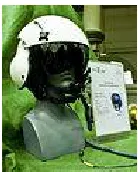
Fig 5Gentex SPH-5 helicopter helmet
IV. OVERVIEW
HMD has one or two small displays, with lenses and semi-transparent mirrors embedded in eyeglasses (also termed data glasses), a visor, or a helmet. The display units are miniaturised and may include cathode ray tubes (CRT), liquid crystal displays (LCDs), liquid crystal on silicon (LCos), or organic light-emitting diodes (OLED). HMDs differ in whether they can display only computer-generated imagery (CGI), or only live imagery from the physical world, or combination. Most HMDs can display only a computer-generated image, sometimes referred to as virtual image. Some HMDs can allow a CGI to be superimposed on real-world view. This is sometimes referred to as augmented reality or mixed reality. Combining real-world view with CGI can be done by projecting the CGI through a partially reflective mirror and viewing the real world directly. This method is often called optical see-through. Combining real-world view with CGI can also be done electronically by accepting video from a camera and mixing it electronically with CGI. This method is often called video see-through.
OPTICAL HMD
An optical head-mounted display uses an optical mixer which is made of partly silvered mirrors. It can reflect artificial images, and let real images cross the lens, and let a user look through it.
Various methods have existed for see-through HMD's, most of which can be summarized into two main families based on curved mirrors or waveguides. Curved mirrors have been used by Laster Technologies, and by Vuzix in their Star 1200 product. Various waveguide methods have existed for years. These include diffraction optics, holographic optics, polarized optics, and reflective optics.
AVIATION AND TACTICAL, GROUND
In 1962, Hughes Aircraft Company revealed the Electrocular, a compact CRT (7" long), head-mounted monocular display that reflected a TV signal in to transparent eyepiece. Ruggedized HMDs are increasingly being integrated into the cockpits of modern helicopters and fighter aircraft. These are usually fully integrated with the pilot's flying helmet and may include protective visors, night vision devices, and displays of other symbology.
Military, police, and firefighters use HMDs to display tactical information such as maps or thermal imaging data while viewing a real scene. Recent applications have included the use of HMD for paratroopers. In 2005, the Liteye HMD was introduced for ground combat troops as a rugged, waterproof lightweight display that clips into a standard US PVS-14 military helmet mount. The self-contained color monocular organic light-emitting diode (OLED) display replaces the NVG tube and connects to a mobile computing device. The LE has see-through ability and can be used as a standard HMD or for augmented reality applications. The design is optimized to provide high definition data under all lighting conditions, in covered or see-through modes of operation. The LE has a low power consumption, operating on four AA batteries for 35 hours or receiving power via standard Universal Serial Bus (USB) connection.
Instruments released on 3 November 2011 two head mounted displays for ski goggles, MOD and MOD Live, the latter based on an Android operating system.
Training and simulation
Fig 6 Paratrooper training with an HMD
A key application for HMDs is training and simulation, allowing to virtually place a trainee in a situation that is either too expensive or too dangerous to replicate in real-life. Training with HMDs covers a wide range of applications from driving, welding and spray painting, flight and vehicle simulators, dismounted soldier training, medical procedure training, and more. However, a number of unwanted symptoms have been caused by prolonged use of certain types of head-mounted displays, and these issues must be resolved before optimal training and simulation is feasible.
SUPPORT OF 3D FORMAT
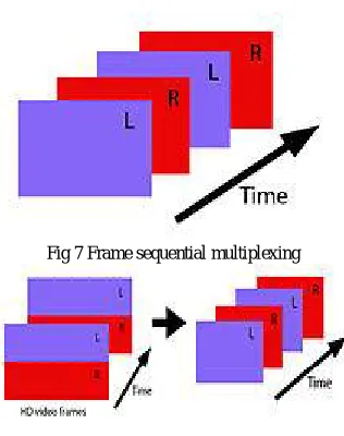
Fig 7 Frame sequential multiplexing
Fig 8 Side-by-side and top-bottom multiplexing
Depth perception inside an HMD requires different images for the left and right eyes. There are multiple ways to provide these separate images:
Use dual video inputs, thereby providing a completely separate video signal to each eye
Time-based multiplexing. Methods such as frame sequential combine two separate video signals into
one signal by alternating the left and right images in successive frames.
Side by side or top-bottom multiplexing. This method allocated half of the image to the left eye and the
The advantage of dual video inputs is that it provides the maximum resolution for each image and the maximum frame rate for each eye. The disadvantage of dual video inputs is that it requires separate video outputs and cables from the device generating the content.
HEAD POSITION SENSING
HMD designs must sense the elevation, azimuth and tilt of the pilot's head relative to the airframe with sufficient precision even under high "g" and during rapid head movement. Three basic methods are used in current HMD technology – optical, electromagnetic and sonic.
HYBRID INERTIAL OPTICAL TRACKING
Hybrid inertial tracking systems employs a sensitive Inertial Measurement Unit (IMU) and an optical sensor to provide reference to the aircraft. The optical sensor also constrains IMU drift. Hybrid trackers feature low latency and high accuracy. The Thales Visionix Scorpion HMCS utilizes a tracker called the Hybrid Optical-based Inertial Tracker (HObIT).
OPTICAL TRACKING
Optical systems employ infrared emitters on the helmet (or flightdeck) infrared detectors in the flightdeck (or helmet), to measure the pilot's head position. The main limitations are restricted fields of regard and sensitivity to sunlight or other heat sources. The MiG-29/AA-11 Archer system uses this technology. The Cobra HMD as used on both the Eurofighter Typhoon and the JAS39 Gripen both employ the optical helmet tracker developed by Denel Optronics (now part of Zeiss Optronics).
ELECTROMAGNETIC TRACKING
Electromagnetic sensing designs use coils (in the helmet) placed in an alternating field (generated in the flightdeck) to produce alternating electrical voltages based on the movement of the helmet in multiple axes. This technique requires precise magnetic mapping of the flightdeck to account for ferrous and conductive materials in the seat, flightdeck sills and canopy to reduce angular errors in the measurement
SONIC TRACKING
Acoustic sensing designs use ultrasonic sensors to monitor the pilot's head position while being updated by computer software in multiple axes. Typical operating frequencies are in the 50 to 100 kHz range and can be made to carry audio sound information directly to the pilot's ears via subcarrier modulation of the sensong ultrasonic sensing signals.
OPTICS
INTEGRATED HELMET AND DISPLAY SIGHT SYSTEM (IHADSS)
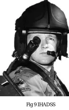
Fig 9 IHADSS
In 1988the U.S. Army fielded the AH-64 Apache and with it the Integrated Helmet and Display Sighting System (IHADSS), a new helmet concept in which the role of the helmet was expanded to provide a visually coupled interface between the aviator and the aircraft. The Honeywell M142 IHADSS is fitted with a 40° by 30° field of view, video-with-symbology monocular display. IR emitters allow a slewable thermographic camera sensor, mounted on the nose of the aircraft, to be slaved to the aviator's head movements. The display also enables Nap-of-the-earth nightnavigation. IHADSS is also used on the Italian Agusta A129 Mangusta.
ZSH-5 / SHCHEL-3UM
The Russian designed Shchel-3UM HMD design is fit to the ZSh-5 series helmet, and is used on the MiG-29 and 27 in conjunction with the R-73 (missile). The HMD/Archer combination gave the MiG-MiG-29 and Su-27 a significantly improved close combat capability and quickly became the most widely deployed HMD in the world.
DISPLAY AND SIGHT HELMET (DASH)
The Elbit Systems DASH III was the first modern Western HMD to achieve operational service. Development of the DASH began during the mid-1980s, when the IAF issued a requirement for F-15 and F-16 aircraft. The first design entered production around 1986, and the current GEN III helmet entered production during the early to mid-1990s. The current production variant is deployed on IDF F-15, and F-16 aircraft. Additionally, it has been certified on the F/A-18 and F-5. The DASH III has been exported and integrated into various legacy aircraft, including the MiG-21. It also forms the baseline technology for the US JHMCS.
The DASH GEN III is a wholly embedded design, where the complete optical and position sensing coil package is built within the helmet (either USAF standard HGU-55/P or the Israeli standard HGU-22/P) using a spherical visor to provide a collimated image to the pilot. A quick-disconnect wire powers the display and carries video drive signals to the helmet's Cathode Ray Tube (CRT). DASH is closely integrated with the aircraft's weapon system, via a MIL-STD-1553B bus.
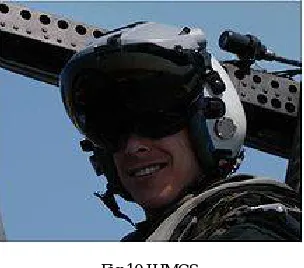
JOINT HELMET-MOUNTED CUEING SYSTEM (JHMCS)
JHMCS is a derivative of the DASH III and the Kaiser Agile Eye HMDs, and was developed by Vision Systems International (VSI), a joint venture company formed by Rockwell Collins and Elbit (Kaiser Electronics is now owned by Rockwell Collins). Boeing integrated the system into the F/A-18 and began low-rate initial production delivery in fiscal year 2002. JHMCS is employed in the F/A-18A++/C/D/E/F, F-15C/D/E, and F-16 Block 40/50 with a design that is 95% common to all platforms.
Fig 10 JHMCS
When combined with the AIM-9X, an advanced short-range dogfight weapon that employs a Focal Plane Array seeker and a thrust vectoring tail control package, JHMCS allows effective target designation up to 80 degrees either side of the aircraft's nose. In March 2009, a successfully 'Lock on After Launch' firing of an ASRAAM at a target located behind the wing-line of the ‘shooter' aircraft, was demonstrated by a Royal Australian Air Force (RAAF) F/A-18 using JHMCS.
SCORPION HELMET MOUNTED CUEING SYSTEM (HMCS)
Thales Introduced the Scorpion Helmet-Mounted Cueing System to the military aviation market in 2008. Scorpion was the winner of the Helmet Mounted Integrated Targeting (HMIT) program in 2010. Scorpion has the distinction of being the first colour HMD introduced. It was developed for targeting pod, gimbaled sensor or high off-boresight missile cueing mission scenarios. Unlike most HMDs, which require custom helmets, Scorpion was designed to be installed on standard issue HGU-55/P and HGU-68/P helmets and is fully compatible with standard issue U.S. Pilot Flight Equipment without special fitting. It is also fully compatible with standard unmodified AN/AVS-9 Night Vision Goggles (NVG) and Panoramic Night Vision Goggles (PNVG).
ASELSAN AVCI
Aselsan of Turkey is working to develop a similar system to the French TopOwl Helmet, called the AVCI Helmet Integrated Cueing System. The system will also be utilized into the T-129 Turkish Attack Helicopter.
TOPOWL-F (TOPSIGHT/TOPNIGHT)
The French thrust vectoring Matra MICA (missile) for its Dassault Rafale and late-model Mirage 2000 fighters was accompanied by the Topsight HMD by Sextant Avionique. TopSight provides a 20 degree FoV for the pilot's right eye, and cursive symbology generated from target and aircraft parameters. Electromagnetic position sensing is employed. The Topsight helmet uses an integral embedded design, and its contoured shape is designed to provide the pilot with a wholly unobstructed field of view.
EUROFIGHTER HELMET-MOUNTED SYMBOLOGY SYSTEM
provisions for embedded NVGs. As with the DASH helmet, the system employs integrated position sensing to ensure that symbols representing outside-world entities move in line with the pilot's head movements.
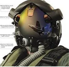
HELMET-MOUNTED DISPLAY SYSTEM
Fig 11 Helmet-Mounted Display System for the F-35 Lightning II Joint Strike Fighter
Vision Systems International (VSI; the Elbit Systems/Rockwell Collins joint venture) along with Helmet Integrated Systems, Ltd. developed the Helmet-Mounted Display System (HMDS) for the F-35 Joint Strike Fighter aircraft. In addition to standard HMD capabilities offered by other systems, HMDS fully utilizes the advanced avionics architecture of the F-35 and provides the pilot video with imagery in day or night conditions. Consequently, the F-35 is the first tactical fighter jet in 50 years to fly without a HUD.A BAE Systems helmet was considered when HMDS development was experiencing significant problems, but these issues were eventually worked out. The Helmet-Mounted Display System was fully operational and ready for delivery in July 2014.
JED EYES TM
Jed Eyes TM is a new system recently introduced by Elbit Systems especially to meet Apache and other rotary wing platform requirements. The system is designed for day, night and brownout flight environments. Jed Eyes TM has a 70 x 40 degree FOV and 2250x1200 pixels resolution.
V. FUTURE TECHNOLOGY
It is developing a standard view Night Vision Cueing & Display (NVCD) for the U.S. navy.
Eye tracking – Eye trackers measure the point of gaze relative to the direction of the head, allowing a computer to sense where the user is looking. These systems are not currently used in aircraft.
Direct retinal projection – Systems that project information directly onto the wearer's retina with a low- powered laser (virtual retinal display) are also in experimentation.
REFERENCES
1. MELZER, J.E toward the HMD as a cognitive prosthesis, head and helmet mounted display X111.design & application proc SPIE 6955, 695501, 2008.
2. BAYER, M.M.Rash, CEandBRINDLE, J.H.Introduction to helmet –mounted displays.in helmet-mounted displays, chapter 3, US army Aerospace mresearch laboratory, 2009
3. GULL, FC and HERD, G.R. An evaluation of proposed causal mechanism for “ejection associated”, Aviat Space Environ Med, 1998, 60PPA2647
4. TEMME, L.A., KALICH, M.E. and CURRY, I.P.ET in head mounted display: sensation, perception issues, chapter12 U.S army aerospace research laboratory
6.CARTER,J.L.visual evoked potential,in DAVBE,J.R. and RUBIN,D.J.(Eds),3rd edition oxford university press,new york,NY,USA,2009
7. JAMES, F.K and CHRIS, B.Effect of head mounted display about infrared sensor includes human factors, 2007, 49, pp797-884 8. CAP396.Registration, Certification and maintenance of Aircraft -A Guide. Cheltenham: Westward Documedia.
9. Kreindler, L.S. (1977) Letter in Flight International.
10. Swatton, P.J. (c.1987) The Operator’s Handbookof Scheduled Aircraft Performance. Author’s draft, Empire Test Pilot’s School. 11. Stinton, D. (1996) Flying Qualities and Flight Testing of the Aeroplane.Oxford: Blackwell Science Ltd.