Analyzing the Secure Overlay Services Architecture under Intelligent DDoS
Attacks
Dong Xuan, Sriram Chellappan, Xun Wang and Shengquan Wang
∗Abstract
Distributed Denial of Service (DDoS) attacks are cur-rently major threats to communication in the Internet. A se-cure overlay services (SOS) architecture has been proposed to provide reliable communication between clients and a target under DDoS attacks. The SOS architecture employs a set of overlay nodes arranged in three hierarchical lay-ers that controls access to the target. Although the architec-ture is novel and works well under simple congestion based attacks, we observe that it is vulnerable under more intel-ligent attacks. We generalize the SOS architecture by intro-ducing more flexibility in layering to the original architec-ture. We define two intelligent DDoS attack models and de-velop an analytical approach to study the impacts of the number of layers, number of neighbors per node and the node distribution per layer on the system performance un-der these two attack models. Our data clearly demonstrate that performance is indeed sensitive to the design features and the different design features interact with each other to impact overall system performance.
1. Introduction
Current level of sophistication in system resilience to Distributed Denial of Services (DDoS) or other forms of at-tacks is far from definite. Tremendous amount of research is being done in order to improve the system security un-der DDoS attacks. Communication reliability over the In-ternet is critical in emergency, medical, and other related services. Apart from providing a high degree of path avail-ability for communication, such systems need to be resilient to attacks from malicious users within and outside of the system that aim to disrupt communication. Also, attacks on
∗ Dong Xuan, Sriram Chellappan, and Xun Wang are with The Department of Computer Information and Science, The Ohio-state University, Columbus, OH 43210. E-mail:
{xuan,chellapp,wangxu}@cis.ohio-state.edu. Shengquan Wang is with the Department of Computer Science, Texas A&M Univer-sity, College Station, TX 77843. E-mail: [email protected].
special nodes or hot spots in such systems can have catas-trophic effects.
A Secure Overlay Services (SOS) architecture has been proposed in [1] in the framework of a set of clients com-municating with a target during critical situations. The SOS architecture provides a high degree of path availability in the presence of random DDoS attacks. The design rationale is to ensure that in the presence of DDoS attacks, the tar-get is not overloaded; the probability of all available paths between clients and the target being compromised is very small; and the attack traffic is dropped. In order to achieve these objectives, the SOS architecture uses a set of
over-lay nodes arranged in 3 layers of hierarchy between the
source and the target through which traffic is authenticated and then routed. The proposed SOS architecture has a va-riety of very nice and novel features. It is simple and eas-ily deployable. In fact with only a very few set of nodes
across the3layers, the SOS architecture provides good
per-formance in terms of providing path availability between clients and the target even without system recovery under on-going attacks. However on a critical note, the following questions are naturally raised while analyzing the system:
• The system can be targeted by intelligent attackers. An
intelligent attacker can have the ability to break into nodes in order to disclose their neighbors and may also be aware of identities of some nodes in the over-lay prior to an attack. By intelligent DDoS attacks, we mean the attacker can launch a large amount of congestion-based DDoS attacks with a certain level of intelligence, such as obtaining system knowledge prior to launching DDoS attacks. An interesting question is, how is the SOS system performance (in terms of path
availability between clients and the target) impacted
under such intelligent DDoS attacks?
• The SOS architecture comprises of three key design
features; number of layers, number of neighbors per node and the node distribution per layer. The
num-ber of layers is set as3. During analysis, the authors
assume the neighbors of a node are all the nodes at the next layer. Are these the best choices? What is the impact of node distribution per layer on the
sys-tem performance? More interestingly, how do these de-sign features combine with each other to impact sys-tem performance under different intensities of intelli-gent DDoS attacks?
In this paper, we aim to address the above issues. Specif-ically, (1) We generalize the SOS architecture such that the design features are flexible and contingent on expected at-tacks. (2) We define two intelligent DDoS attack models and develop an analytical approach to analyze the general-ized SOS architecture under these attack models. The ap-proach is general and can be applied to analyze other sys-tems. (3) We analyze the generalized SOS architecture in detail under intelligent DDoS attacks towards understand-ing the sensitivity of system performance to each design feature. We observe that the number of layers and the num-ber of neighbors per node have opposite effects on the re-silience to break-in and congestion attacks. More layers and less neighbors per node improve resilience to break-in at-tacks, while the reverse is true for congestion based attacks. In order to compensate for the effects of break-in and con-gestion attacks, there is a clear trade-off in the layering as well as the number of neighbors per node. We also observe that the system performance is sensitive to the node distri-bution per layer, particularly when the number of neighbors per node is large.
2. The SOS architectures
In this section, we provide a brief description to the over-all SOS system [1] from the point of view of the basic ar-chitecture and the attack scenarios analyzed there.
Source Point SOAP SOAP Beacon Beacon Beacon Secret Servlet Secret Servlet Secret Servlet Target Filtered region
Figure 1. The original SOS architecture.
In the SOS architecture shown in Fig. 1, communication
between clients and a target is through3 intermediate
lay-ers. These layers are SOAP (Secure Overlay Access Point), Beacons and Secret Servlets. A client that wishes to com-municate with a target first contacts a node in the SOAP layer. The node in the SOAP layer contacts a beacon, which then contacts a secret servlet, which routes the data through a filter towards the target. A set of filters acts as a firewall surrounding the target. In this architecture each source point
is aware of nodes in the SOAP layer, which are aware of the Beacons, which know the Secret Servlets, which in turn know the identities of the filters. Nodes in each layer (and the filters) ensure that they route packets to the next layer after verification that the packet indeed arrived from a legit-imate node in a lower layer. The underlying routing proto-col used, is Chord [2] for more anonymity. The performance metric is the probability that a client can communicate suc-cessfully with the target by finding a path to it. For analy-sis purposes the attack model is random congestion-based DDoS attacks. Although a congested node does not allow attack traffic to pass through because of validation, it never-theless becomes non functional due to DDoS attacks com-promising path availability.
We wish to refer back to the questions about the SOS architecture raised in Section 1. The architecture although performs well for random congestion based attacks, will be fragile in the presence of intelligent attacks like break-in at-tacks as we show later. Under break-in atat-tacks, the attacker can easily find the location of nodes towards the target. We
believe that fixing the number of layers as3is not always
the optimal choice. We aver that for given system resources, an increase in the number of layers will enable pure conges-tion based attacks to be more successful. In fact fixing the
number of layers as1is the best choice to defend against
such attacks. We believe that system performance is sensi-tive to design features and attacks and the architecture needs to be flexible in order to realize better performance under different attacks. Source Point Target Layer 1 Node Layer 1 Node Layer L Node Layer L Node Layer L Node Layer i+1 Node Layer i+1 Node Layer i+1 Node Layer i Node Layer i Node Layer i Node Layer 2 Node Layer 2 Node Layer 2 Node Filtered region
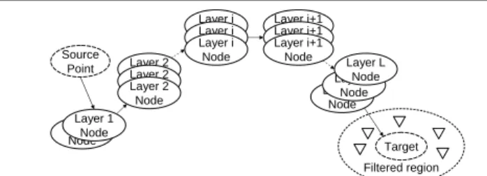
Figure 2. The generalized SOS architecture.
Following the above discussions, we generalize the orig-inal SOS architecture. In simple terms, our generalized ar-chitecture extends from the original SOS arar-chitecture and consists of multiple layers of nodes as shown in Fig. 2. The
number of layers is denoted byL. The layering features are
given below.
• The first layer and the last layer provide similar
func-tionality as the SOAP layer and the Secret Servlet layer respectively in the original SOS architecture.
• The intermediate layers perform the functionality of
that in our generalized architecture, there can be mul-tiple layers. Similar to the SOS architecture, nodes in
Layeri+ 1will forward traffic that arrive only from a
node at Layeri.
Having described our generalized architecture from the layering perspective, we formally introduce two other
de-sign features; the number of nodes in Layeridenoted byni
and the number of neighbors a node in Layeri−1has in
Layeri(referred to as the mapping degree), denoted asmi.
The novelty of our generalized architecture is its
flexibil-ity. Here,L,niandmiare designed depending on the
sys-tem resources and attacks. Our architecture being flexible can be designed easily considering other factors such as de-lay performance, guaranteed delivery for special clients etc.
3. Analysis of the Generalized SOS
architec-ture
In the following we conduct an extensive analysis to our generalized SOS architecture on two attacks models: one-burst attack model and the successive attack model. In both the attack models, the attacker conducts the attack in two phases, (1) break-in attack phase and (2) congestion at-tack phase. The break-in atat-tack phase discloses some nodes while the congestion attack phase congests the nodes based on the information about the disclosed nodes by the break-in attacks. The only difference between the one-burst and the successive attack model is that in the former, the break-in attack phase is conducted break-in one round, while break-in the latter it is conducted in successive rounds.
The system we study consists of a total ofN overlay
nodes, of whichn nodes are in the SOS system (denoted
as SOS nodes). In our attack model, the attacker has
re-sources to launch break-in attacks onNT nodes and
con-gestNC nodes. The attacker may have some prior
knowl-edge about the identities of the SOS nodes before the
at-tack. With a probabilityPB, the attacker can successfully
break into a node.
We define system performance as the probability,PSthat
a client can find a path to communicate with the target un-der on-going attacks. In this paper, we do not consiun-der the dynamics of system repair to attacks, which is our future work.
3.1. Under one-burst attack without any prior
knowledge about the SOS nodes
3.1.1. Attack model The attacker will spend all the
break-in attack resources randomly break-in one round and then launch the congestion attack. Even though this model may appear simple, in reality such a type of attack is possible when say, the system is in a high state of alert anticipating imminent
attacks, which the attacker knows and still wishes to pro-ceed with the attack. Here we assume the attacker has no prior knowledge about the SOS nodes.
1 2
client
good node congested node broken-in node good filter congested filter
target
i L L+1
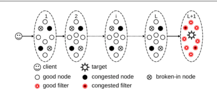
Figure 3. A Snapshot of the generalized SOS architecture under the intelligent DDoS at-tacks.
Before proceeding with the analysis, we emphasize here that the system/attack model we are analyzing is different
from the one in [1] although the performance metric (PS)
is the same; (1) In our case, the break-in attacks will dis-close some nodes, and the congestion attacks will focus on such nodes to attack and are not just performed in a to-tally random fashion. (2) Even before the start of an attack, the attacker has some prior knowledge about SOS nodes. Although in the analysis of the one-burst attack we dis-count this situation, it is not the case in the successive at-tack model we analyze which introduces additional com-plexity. (3) In the analysis of the original SOS architecture, it is assumed that each node can simultaneously provide the functionality of nodes at multiple layers. In the presence of break-in attacks, allowing this possibility is very dan-gerous in the sense once such a node is broken-into, nodes in several other layers will be disclosed and so we do not make this assumption. We observe that the factors men-tioned above make our analysis harder, but is more realis-tic and the resulting architecture from this analysis is natu-rally more robust.
The key defining feature of our analysis is in
determin-ing the set1 of attacked nodes in each layer. The intuitive
way to analyze the system is to list all possible combina-tions of attacked nodes in each layer. The overall system performance can be obtained by calculating the probability
of occurrence of each combination and calculatingPS for
that combination and appropriately summarizingPS over
all possible combinations. It is easy to see that there could
be many such possible combinations. For a system withL
layers andn nodes evenly distributed, such combinations
will be inθ(n
L)
2L. For a system3layers and100SOS nodes
evenly distributed, we have about1.0∗1010combinations.
Practically, it is not scalable to analyze the system in this fashion. To circumvent the scalability problem, we take an alternative approach. Since the system and attack parame-tersN, n, NC, NT are large, based on the weak law of large
number, we use the average case analysis approach. We cal-culate the average number of attacked nodes in each layer
to obtainPS.
Recall thatPSis the probability that a user can
success-fully communicate with the target. In our architecture, a node maintains a neighbor table that consists of nodes in its next higher layer and the number of neighbors is decided by the mapping degree policy. Upon receiving a message,
a node in Layeriwill contact a node in Layeri+ 1from
its neighbor table and forward the received message to that node. This process repeats till the target is reached via the nodes in successive higher layers. The routing thus takes place in a distributed fashion. We call a bad or
compro-mised overlay node as one that has either been broken into
or is congested and cannot route a message. The other over-lay nodes are good nodes. The routing table will contain bad entries during break-in or congestion attacks that can cause failure of a message being delivered. A snapshot of the sys-tem under an on-going attack is shown in Fig. 3. To compute
PS, first we should know the probabilityPithat a message
can be successfully forwarded from Layeri−1to Layeri
(1≤i≤L+ 1). Here LayerL+ 1refers to the set of
fil-ters that encompass the target. In our analysis, we consider this layer also because it is possible that their identities can
be disclosed during a successful break-in at LayerL. With
the property of distributed routing algorithm, we can obtain
PS by direct product of allPi’s, i.e.,PS = ΠLi=1+1Pi.
Obvi-ously,Pidepends on the availability of good nodes in Layer
ithat are in the routing table of nodes in Layeri−1. Towards
this extent, defineP(x, y, z)as the probability that a set ofy
nodes selected at random fromx > ynodes contains a
spe-cific subset ofznodes, thenP(x, y, z) =
µ y z ¶ / µ x z 
ify ≥ z, and otherwiseP(x, y, z) = 0. Definesi as the
number of bad nodes in Layeri. Recall that each node in
Layeri−1 will havemi neighbors in Layeri. Then, on
an averageP(ni, si, mi)is the probability that all next-hop
neighbors in Layeriof an overlay node in Layeri−1are
bad nodes. HencePi = 1−P(ni, si, mi). Thus, the
prob-abilityPS that each message will be successfully received
by the target can be expressed as follows:
PS = ΠLi=1+1Pi= ΠiL=1+1(1−P(ni, si, mi)). (1)
In (1), onlysi’s are undetermined. Recall that a bad node
is one that has either been broken-into or is congested. If
we definebi andci as the number of nodes that have been
broken-into and the number of congested nodes respectively
in Layeri, we havesi=bi+ci.
The nodes that were broken in will disclose some SOS nodes. In our model, once a node is broken into, it is com-promised and the attacker will not congest that node. Thus at the end of the break-in attack phase, there is a set of nodes disclosed, from which we have to discount nodes that have been successfully broken into. The resulting set of nodes is the one the attacker will try to congest first.
We assume the NT break-in trials are uniformly
dis-tributed on the nodes in the system. The average number
of broken-in overlay nodes, NB = PBNnNT. We define
hi as the number of nodes on which a break-in attempt
has been made in Layer i. For Layer i, hi = nNi(NT),
andbi = PB(nNi)(NT)fori = 1, . . . , L. We assume here
that the filters are special and cannot be broken into. Hence bL+1 = 0.
At the start of the congestion attack phase, the attacker needs to know the set of nodes disclosed which have not been attempted to break into. We calculate this set as
fol-lows. LetYi,j be a random variable whose value is1when
thejthin Layeriis either a disclosed node or one on which
a break-in attempt has been made. Letzidenote the
aver-age number of nodes that have been disclosed or have been tried to be broken into. Thus,
zi=E( ni X j=1 Yi,j) = ni X j=1 E(Yi,j) = ni X j=1 Pr{Yi,j= 1}. (2)
The probability that the jthnode in Layer iis neither
a disclosed node nor one on which a break-in attempt has
been made is given by(1− mi
ni)
bi−1(1− hi
ni). The same
node can be disclosed by more than one node in the
previ-ous layer. The part(1−mi
ni)
bi−1 excludes such overlaps.
Pr{Yi,j= 1}= 1−(1− mi ni )bi−1(1−hi ni ), (3)
and thenziis given by,
zi = ni X j=1 (1−(1−mi ni )bi−1(1−hi ni )) (4) = ni(1−(1− mi ni )bi−1(1−hi ni )). (5) We denotedN
i the number of nodes which are disclosed but
haven’t been attempted to break-in: dN i =zi−hi=ni(1−(1− mi ni )bi−1(1−hi ni ))−hi, (6) fori= 2, . . . , L+ 1. Apart fromdN
i , there is a set of nodes that have been
dis-closed on which a break-in attempt has been made
unsuc-cessfully. This set is denoted bydA
i and is given by,
dAi = hi−bi X j=1 (1−(1−mi ni )bi−1) = (h i−bi)(1−(1− mi ni )bi−1). (7)
Note that nodes in the first layer cannot be disclosed due
to a break-in attack and sodN
i =dAi = 0.
Thus the attacker will congest nodes in the setdN
i and
dA
i as their identities have been disclosed and they have not
been broken into. DefineND to be the average total
num-ber of nodes that are disclosed but not broken-into
success-fully in the system, whereND = PLi=1+1(dNi +dAi ).
Re-call that NC is the overall number of overlay nodes that
the adversary can congest. Considering the attack conges-tion mechanism, there are two cases:
• NC ≥ ND: In this case, all ND disclosed nodes
will be congested. Since the attacker still has
capac-ity to congest NC −ND nodes, it will expend its
spare resources randomly. The extra congested nodes will be uniformly randomly chosen from the
remain-ingN−NB−(ND−dNL+1−dAL+1)good nodes. We
emphasize thatdN
L+1 anddAL+1 are part of the filters
and are excluded fromND to determine the
remain-ing overlay nodes that are targets for random
conges-tion2. Therefore, the total number of congested
over-lay nodes in Layeriis,
ci= dN i +dAi + (NC−ND)∗ ( ni−bAi−dNi−dAi N−NB−(ND−dNL+1−dAL+1) ), i= 1, . . . , L, dN i , i=L+ 1. (8)
• NC < ND: The attacker can randomly congest the
subset ofNCcandidates amongNDdisclosed nodes.
In this case, ci= NC ND (dN i +dAi ), (9) fori= 1,2, . . . , L+ 1.
Recall thatsi =bi+ciis the set of bad nodes in Layeri.
We then use (1) to computePS.
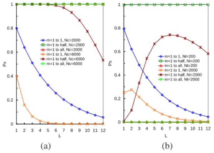
3.1.2. Numerical Results and Discussion Fig. 4 shows
the relationship betweenPS and the layering and mapping
degree under different attack intensities. We discuss the is-sue of node distribution in the successive attack model. The mapping degrees used here are: one to one mapping which means each SOS node has only one neighbor in the next layer; one to half mapping which means each node has half of all the nodes in the next layer as its neighbors; and one to all mapping which means each node has all the nodes in next layer as its neighbors. Other system and attack
config-uration parameters are:N = 10000,n = 100,PB = 0.5,
the SOS nodes are evenly distributed among layers. The
number of filters is set as10. In Fig. 4 (a),NT is set as
2 In our model, the filters are special and can be congested only upon disclosure and not randomly.
0and we evaluate performance under two congestion
inten-sities:NC = 2000 andNC = 6000representing
moder-ate and heavy congestion attacks respectively . In Fig. 4 (b),
we fixNC = 2000and analyze two intensities of break-in:
NT = 200andNT = 2000. We make the following
obser-vations; 0 0.2 0.4 0.6 0.8 1 1 2 3 4 5 6 7 8 9 10 11 12 L P s m=1 to 1, Nc=2000 m=1 to half, Nc=2000 m=1 to all, Nc=2000 m=1 to 1, Nc=6000 m=1 to half, Nc=6000 m=1 to all, Nc=6000 0 0.2 0.4 0.6 0.8 1 1 2 3 4 5 6 7 8 9 10 11 12 L P s m=1 to 1, Nt=200 m=1 to half, Nt=200 m=1 to all, Nt=200 m=1 to 1, Nt=2000 m=1 to half, Nt=2000 m=1 to all, Nt=2000 (a) (b)
Figure 4. Sensitivity ofPS toLandmi under
different attack intensities.
• Fig. 4 (a) shows that under the same attack intensities,
different layer numbers result in differentPS. When
NT = 0 (pure random congestion attack), asL
in-creases,PS goes down. This is because there are less
nodes per layer, and under random congestion, few nodes per layer are left uncompromised. This behav-ior is more pronounced when the mapping degree is high. We wish to remind the reader about the original SOS architecture, where the number of layers is fixed
as3and the mapping degree is one to all for
defend-ing against random DDoS congestion attacks (same as the attack model we analyze here). From the above dis-cussion we can see that fixing the number of layers as
3is not the best solution for such a type of attack.
• For any Layer L, a higher mapping degree (more
neighbors for each node) means more paths from nodes in one layer to nodes in the next layer, thus
in-creasingPSin Fig. 4 (a) under the absence of break-in
attacks. Under break-in attacks, a high mapping de-gree is not always good as more nodes are disclosed during break-in attacks. For instance when the
map-ping is one to all,PS = 0in Fig. 4 (b). Thus the effect
of mapping typically depends on the attack intensi-ties of the break-in and congestion phase.
• Finally we see that an increase inNC andNT
natu-rally leads to a decrease in PS, because more nodes
3.2. Under a successive attack with the prior
knowledge about the SOS nodes
3.2.1. Attack model Our successive attack model extends
from the one-burst attack model in two ways; (1) the at-tacker has some prior knowledge about the first layer SOS
nodes. LetPErepresent the percentage of nodes at the the
first layer known to the attacker before an attack, (2) the
break-in attack phase is conducted inRrounds (R > 1),
i.e., the attacker will launch its break-in attacks successively rather than in one burst. In this attack model, more SOS nodes are disclosed in a round by round fashion thus
accen-tuating the effect of attack. However in reality,Rcannot be
too large as that would allow the system enough time to de-tect and recover from an on-going attack before the attack is completed.
The strategy of the successive attack is shown in
Algo-rithm 1. We denoteβto be the available break-in resources
at the start of each round andβ =NT at the start of round
1. For each round, the attacker will try to break-into a
min-imum ofαnodes and is fixed as NT
R . If the number of
dis-closed nodes is more thanα, the attacker borrows resources
fromβto attack all of them. Otherwise it attacks the nodes
disclosed and some other randomly chosen nodes to utilize
αfor that round. The spare break-in attack capacity
avail-able keeps decreasing till the attacker has exhausted all of
itsNT resources. At any round, if the attacker has
discov-ered more SOS nodes than its available attack resources (β),
it tries to break into a subset (β) of the disclosed nodes and
starts the congestion phase. The attacker will congest all disclosed nodes and more; or only a subset of the disclosed
nodes depending on its congestion capacityNC. We assume
Xj be the number of nodes whose identities are known to
the attacker at the start of roundj. Here we assume the
at-tacker will not attempt to break into a node twice and a node broken into is not congested. Although there can be other variations of such successive attacks, we believe that our model is representative enough.
3.2.2. Analysis We again use the average case approach
to analyze the system and derivePS. The problem typically
is in discounting the overlaps among the bad (disclosed or broken-in) nodes. In the one-burst attack model we ana-lyzed before, we had to take care of three possible over-lap scenarios; (1) a disclosed node could have been already broken-into, (2) the same node being disclosed by multi-ple lower layer nodes and (3) a disclosed node could have been unsuccessfully broken-into. The complexity in over-lap is accentuated here due to the nature of the successive attack model. This is because there are multiple rounds of break-in attacks before congestion. We thus have to con-sider the above overlaps in the case of multiple rounds as well. In order to preserve the information about a node per
Algorithm 1 Pseudocode of the successive attack strategy.
Parameters:System parameters :N,n,L,PBand attack
pa-rameters :NT,NC,R,X1,β,α.
Phase 1 of the attack strategy:
1: β =NT,α= NRT;
2: forj= 1toRdo
3: ifXj < α < βthen
4: launch break-in attack on allXj nodes and
ran-domly launch break-in attack onα−Xjnodes and
calculate the setXj+1disclosed nodes;
5: updateβ=β−α;
6: end if
7: if Xj < β≤αthen
8: launch break-in attack on allXj nodes and
ran-domly launch break-in attack onβ−Xjnodes and
calculate the setXj+1disclosed nodes;
9: break;
10: end if
11: ifα≤Xj< βthen
12: launch break-in attack on allXjnodes and
calcu-late the setXj+1disclosed nodes;
13: updateβ=β−Xj;
14: end if
15: ifXj ≥βthen
16: launch break-in attack on β nodes among Xj
nodes and calculate the setXj+1disclosed nodes;
17: break;
18: end if
19: end for
20: CalculateND;
Phase 2 of the attack strategy:
1: ifNC≥NDthen
2: congest theNDnodes and randomly congest (NC−
ND) nodes;
3: else
4: congestionNCnodes amongNDnodes randomly;
5: end if
round, we introduce the subscriptjfor round along with the
subscriptithat refers to layer information.
At the beginning of each roundj, the attacker will base
its attack on the set of nodes disclosed at the completion
of roundj−1. We denote the set of nodes which are
dis-closed at roundj−1on which a break-in attempt is made
in roundjashD
i,j. Depending on its spare capacity for that
round, the attacker will also select more nodes to randomly
break-into. We denote this set of nodes ashA
i,j. We define
hi,j = hDi,j +hAi,j. It is the number of nodes on which
break-in attempts (successfully/unsuccessfully) have been
made at Layeriin roundj. Once the attacker has launched
its break-in attacks on thesehi,j nodes, it will successfully
break into some of them. We denotebD
i,jandbAi,jas the set
of nodes successfully broken into and denoteuD
as the set of nodes unsuccessfully broken into after
launch-ing the break-in attacks on thehD
i,jandhAi,jset of nodes
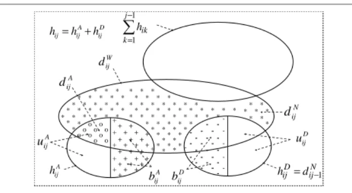
re-spectively. D ij A ij ij h h h = + * * + + + + + + + + + + + + + + + + + + + + + + +++++ + + -* o o * o o o o o o o * * * * * * * * * * * * * * * * * * * * * * * * * * * * * * * * * * * * * * * * * * * * * * * * * * * * * * * * * * * * * * * * * * * * * * * * * * * * * * * * * * * * o D ij b A ij b D ij u A ij u A ij h A ij d W ij d N ij d N ij D ij d h = −1
∑
− = 1 1 j k ik hFigure 5. Node demarcation in our succes-sive attack at the end of Roundj.
Breaking into nodes in setsbD
i,j andbAi,j will disclose a
set of nodes denoted bydW
i,j. This set,dWi,jwill overlap with
(1) the nodes attacked until all previous rounds denoted by
Pj−1
k=1hi,k, (2) the nodes in setuAi,j. We define such a set
of the overlapped nodes asdA
i,j, (3) the nodes in setbAi,j, (4)
the nodes in setbD
i,j anduDi,j. Fig. 5 shows such overlaps
at the end of roundj. After discounting all the above
over-laps fromdW
i,j, we can get the set of disclosed nodes which
have never been attacked till the end of roundj. We
de-fine this set asdN
i,j. We defineXj+1 =PLi dNi,j, on which
the attacker will launch break-in attacks at roundj+ 1.
In the following, we proceed to describe the calculation of the above sets and then compute the number of congested
nodes. Thus, we typically computesiand apply (1) to
ob-tainPS. We would like to take caseXj< α < βjin
Algo-rithm 1 as an example. This is the most representative case among the ones possible. We also consider the other possi-ble cases briefly after analyzing this case. In this case, the
attacker at the beginning of roundj of its break-in attack
phase has resources (α−Xj) to break into more nodes than
those disclosed already prior to that round. The attacker will expend these resources randomly.
The break-in attack phase At the beginning of roundj, the attacker will launch break-in attacks on the set of nodes
dis-closed in roundj−1, i.e.dN
i,j−1. The remaining break-in
re-sources of that round will be randomly used. We then have,
hD i,j=di,j−1, (10) hA i,j = ni−di,j−1− Pj−1 k=1hi,k N−Xj−PLq=1 Pj−1 k=1hq,k (α−Xj), (11)
hi,j = hAi,j+hDi,j, (12)
bDi,j = PB∗hDi,j, (13) bA i,j = PB∗hAi,j, (14) uDi,j = (1−PB)∗hDi,j, (15) uA i,j = (1−PB)∗hAi,j, (16) fori= 1,2, . . . , L.
In (10), note however thatdi,j−1is0fori= 1. This is
because the nodes at the first layer cannot be disclosed by
means of a break-in attack in any roundj. We definebi,jas
the summation ofbA
i,jandbDi,jand,
bi,j = PB∗di,j−1+PB( ni−di,j−1− Pj−1 k=1hi,k N−Xj−Pq=1L Pj−1 k=1hq,k ) (α−Xj), (17) fori= 1,2, . . . , L.
The next part is to compute the set of nodesdN
i,janddAi,j.
As discussed above, we have to extract the setdN
i,j from
dW
i,j. Similar to the discussion in the one-burst attack case
and from (5), (6) and (7), we calculatedN
i,janddAi,j. We first
calculate the set of nodes that have been either disclosed or
attacked. Forbi−1,j >0andi= 2,3, . . . , L,
zi,j = ni(1−(1− mi ni )bi−1,j(1− Pj k=1hi,k ni ))(18) dN i,j = zi,j− j X k=1 hi,k. (19)
Note that in our attack model, the attacker will not try to
break into a node twice. Hence, to calculatedN
i,j, fromzi,j,
we subtract the nodes on which a break-in attempt has been made. We then have,
dAi,j= (hAi,j−bAi,j)(1−(1−
mi
ni
)bi−1,j), (20)
forbi−1,j >0andi= 2,3, . . . , L.
We now wish to clarify the reader about the situations involving particular cases for the successive attack. Apart from the general case we have discussed, there are three
other cases: (1)Xj < β ≤ α, (2) α ≤ Xj < βand (3)
β ≤ Xj. For case (1), all the formulas we derived for the
general case can be directly applied, except thatαhas to
be replaced byβ. For case (2), all the formulas in the
gen-eral case can be applied except thathA
i,j = 0. For case (3),
we havehA
i,j = 0, and the formulas derived in the general
case are not directly applicable. In this case, there are some disclosed nodes that the attacker does not try to break into due to exhaustion of all break-in resources. Such nodes will be attacked during the congestion phase. We denote this set
of nodes in Layeriafter roundj asfi,j. We wish to state
the attacker completes its break-in attack phase at roundj. Thus, fi,j = di,j−1−( di,j−1 Xj )β, (21) hAi,j = 0, (22) hD
i,j = di,j−1−fi,j, (23) fori= 1,2, . . . , Land dNi,j= 0, i= 1, ni(1−(1−mnii)bi−1,j (1− Pj k=1hi,k+ Pj k=1fi,k ni )) −Pj k=1hi,k−Pjk=1fi,k, i= 2,3, . . . , L+ 1, (24) wherebi−1,j >0andd A
i,jis same as one in the general case.
The congestion attack phase Let the final round of the
break-in attack beJ(J ≤R). DefiningNDto be the
num-ber of disclosed nodes but not broken-into, we have,
ND = L X i=1 J X k=1 uDi,k+ J X k=1 dNL+1,k + L X i=2 dN i,J + L X i=1 fi,J + L X i=1 J X k=1 dA i,k. (25)
We have the total number of broken-in nodes, NB =
PL
i=1
PJ
k=1bi,k.
IfNC ≥ ND, we have the number of congested nodes
per layerci, as,
ci= PJ k=1uDi,k+dNi,J + PJ k=1dAi,k +Fi,J+ (NC−ND)(ni −PJ
k=1bi,k−PJk=1uDi,k−dNi,J −PJ k=1dAi,k−Fi,J)/(N −NB−(ND−Pjk=1dNL+1,k)), i= 1,2, . . . , L, Pj k=1dNL+1,k, i=L+ 1. (26) IfNC < ND, we have, ci= NC ND ∗( PJ k=1uDi,k+dNi,J +Fi,J+PJk=1dAi,k), i= 1,2, . . . , L, NC ND( PJ k=1dNL+1,k), i=L+ 1. (27)
Denotingbi =PJk=1bi,k we have the set of bad nodes
in Layeri,si=bi+ci. We then use (1) to computePS.
Note that prior knowledge about identities of the first
layer SOS nodes,PE, determinesX1, i.e.X1=n1∗PE. In
fact, we can consider this information as that obtained from a break-in attack at Round 0. The number of nodes
“dis-closed” at Round 0 isn1∗PE, all of which are distributed at
the first layer. At round1, the attacker will launch its
break-in attack based on this break-information. Thus bi,j, dNi,j, ci etc.
can be calculated by application of equations (10) to (27).
We wish to point out that if we setPE = 0andR = 1, the
successive attack model degenerates into the one-burst
at-tack model. Thus the formulas to computebi,j, dNi,j, cietc.
will be simplified to the corresponding ones derived in the previous sub-section.
3.2.3. Numerical Results and Discussion In the
follow-ing, we discuss the system performance (PS) under the
successive attack. Unless otherwise mentioned, the default
system and attack parameters are N = 10000, n=100,
NC=2000,NT=200,R = 3,PB=0.5andPE=0.2and the
SOS nodes are evenly distributed among the layers. We in-troduce two new mapping degrees here, namely one to two
mapping, meaning each SOS node has2 neighbors in the
immediate higher layer; and the other is, one to five
map-ping, meaning each node has5neighbors in the next layer.
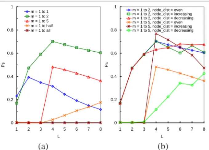
0 0.2 0.4 0.6 0.8 1 1 2 3 4 5 6 7 8 L P s m = 1 to 1 m = 1 to 2 m = 1 to 5 m = 1 to half m = 1 to all 0 0.2 0.4 0.6 0.8 1 1 2 3 4 5 6 7 8 L P s m = 1 to 2, node_dist = even m = 1 to 2, node_dist = increasing m = 1 to 2, node_dist = decreasing m = 1 to 5, node_dist = even m = 1 to 5, node_dist = increasing m = 1 to 5, node_dist = decreasing (a) (b)
Figure 6. Sensitivity ofPS toL,mi and node
distribution.
Fig. 6 (a) shows the impact ofLonPS under different
mapping degrees. Similar to Fig. 4 (a)(b),PS is sensitive to
Land the mapping degree even whenNT >0andR >1.
Among the current configurations, the one withL= 4and
mapping degree one to two provides the best overall perfor-mance.
Fig. 6 (b) gives us an insight on the impact of node
dis-tribution onPS whenLand the mapping degree changes.
Other parameters remaining unchanged, here we show sen-sitivity of performance to three different node distributions per layer. The first is even node distribution where the
num-ber of nodes in each layer is the same (NT
L ). The second is
increasing node distribution, where the number of nodes in
the first layer are fixed (NT
L ). This is to maintain a degree of
in an increasing distribution of1 : 2 :. . .:L−1. The third is decreasing node distribution where the number of nodes
in the first layer is fixed (NT
L ) and those in the other
lay-ers are in decreasing order ofL−1 :L−2 :. . .: 1.
We make the following observations. The node
distribu-tion does impact performance. The sensitivity ofPS to the
node distribution seems more pronounced for higher map-ping degrees (more neighbors per node). A very interesting observation we make is that increasing node distributions performs best. This is because when the mapping degree is larger than one to one, breaking into one node will lead to multiple nodes being disclosed at the next layer, hence the layers closer to the target will have more nodes dis-closed and are more vulnerable. More nodes at these lay-ers can compensate the damage of disclosure . Also we ob-serve that as the number of layers increases, the sensitivity
to node distribution gradually reduces. This is because asL
increases, the difference in the number of nodes per layer turns to be less for the different node distributions.
0 0.2 0.4 0.6 0.8 1 1 2 3 4 5 6 R P s L=1 L=2 L=3 L=4 L=5 L=6
Figure 7. Sensitivity ofPS toR under
differ-entL.
Fig. 7 shows the impact ofR onPS under different L
with mapping degree one to five. The nodes are evenly
dis-tributed among the layers in this case. Overall,PS is
sen-sitive and decreases whenRincreases. For larger values of
L,PS is less sensitive toR because more layers can
pro-vide more protection from break-in attack even for higher round numbers.
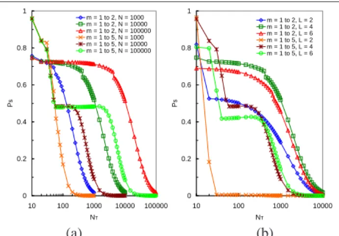
In Fig. 8 we show howPS changes withNT as the other
system side parameters change. Fig. 8 (a) shows how the mapping and total number of overlay nodes influences the
relation betweenNT andPS. In this configuration, we set
NC = 2000 and even SOS node distribution. Fig. 8 (b)
shows the sensitivity ofPS to changingLand mapping
de-grees under changingNT. We make the following
observa-tions.
• PSis sensitive toNT. A largerNT results in a smaller
PS. For higher mapping degrees,PS is more sensitive
to changingNT. The reason follows from previous
dis-0 0.2 0.4 0.6 0.8 1 10 100 1000 10000 100000 NT P s m = 1 to 2, N = 1000 m = 1 to 2, N = 10000 m = 1 to 2, N = 100000 m = 1 to 5, N = 1000 m = 1 to 5, N = 10000 m = 1 to 5, N = 100000 0 0.2 0.4 0.6 0.8 1 10 100 1000 10000 NT P s m = 1 to 2, L = 2 m = 1 to 2, L = 4 m = 1 to 2, L = 6 m = 1 to 5, L = 2 m = 1 to 5, L = 4 m = 1 to 5, L = 6 (a) (b)
Figure 8. Sensitivity ofPS toNT under
differ-entL,miandN.
cussions that a higher mapping degree discloses more nodes under break-in attacks.
• From Fig. 8, there is a portion of the curve, where
PSalmost remains unchanged for increasingNT. This
stable part is due to advantages offered by means of the layering of SOS architecture to disclosure-based
break-in attack. The down slide inPS beyond the
sta-ble part shows the effect of random break-in attack apart from disclosure-based attack.
• For a fixed NT, an increase in the total number of
overlay nodesN, decreases the chance that a random
break-in attack is launched on an SOS node, andPS
does increase.
Due to the space limitations, we do not report our
anal-ysis on the sensitivity ofPS toNC. Interested readers can
refer [3]. However, we summarize all our findings as fol-lows. The attack strategies and intensities significantly im-pact system performance. However, the imim-pacts are deeply influenced by the system design features. Larger values of
Land smaller mapping degrees improve system resilience
to break-in attacks, while the reverse is true for conges-tion based attacks. In order to compensate for the effects of break-in and congestion attacks, there is a clear trade-off in the layering as well as mapping degree. We also demon-strated why increasing node distributions perform better than other node distributions. Thus, if the system is de-signed carefully keeping potential attack scenarios in mind, more resilient architectures can be designed.
4. Related Work
The main purpose of this work is for analyzing system resilience against Distributed DoS attacks. The survey in [1] is exhaustive and interested readers can refer to that paper.
In the following, we would like to focus on work in over-lay and anonymity systems.
Overlay networks have been widely used for
multicasting[4], routing [5] and file sharing [6] etc. How-ever, less work has been reported on the use of overlay so-lutions to enhance security of communication systems. Three of them are [1], [7] and [8]. Mayday [7] is a gener-alized SOS architecture that separates the overlay routing and lightweight packet filtering and provides a more pow-erful set of choices for each layer. However, it does not address the problems of layering and mapping degree is-sues, which our paper focuses on. An overlay solution to track DDoS floods is proposed in [8].
The goal of SOS and our generalized SOS is to ensure that, with high probability any client can find a path to the target under DDoS attacks. The attacker needs to find out the location of target to congest it or disrupt all possible in-termediate paths. Hence the target protection is very impor-tant. The key technology used by SOS is providing receiver (target) location anonymity by allowing sources to contact SOAP layer nodes only. The attacker has no idea about suc-cessive paths taken by messages or the location of the tar-get. Besides using the anonymity approach, SOS also tries to ensure a path from clients to the target by putting multi-ple connections between nodes in successive layers. A lot of anonymity systems, particularly ones aiming to achieve re-ceiver anonymity, depend on one or more third party nodes to generate an anonymous path [9, 10], which is not good for SOS. SOS cannot rely on a centralized node to achieve receiver anonymity, since the centralized node can itself be the target of a DDoS attack. SOS uses multiple layer-ing technology to achieve receiver location anonymity in a distributed fashion. Our generalized architecture further ex-tends these technologies.
5. Final Remarks
Our contributions in this paper are (1) systematically studying the existing SOS architecture from the perspective of its basic design features, (2) proposing a generalized SOS architecture by introducing flexibility to the design features, (3) defining two intelligent DDoS attack models and devel-oping an analytical approach towards analyzing the gener-alized SOS architecture under these two attack models. We make interesting observations on the sensitivity of system performance to the design features. There are some open is-sues related to this study, mentioned below:
More sophisticated attack models and Dynamic repair:
We can further refine our attack model by introducing more intelligence. For instance, during the break-in phase of the attack, the attacker can also find previous layer nodes of an attacked node by monitoring the on-going traffic and can also build up a layering model of the architecture causing
an increased damage to the system. Also, we do not con-sider system repairs here. It is very hard, if not impossible, to mathematically analyze such sophisticated attacks with dynamic repair mechanisms. Also, attacks on the underly-ing network are possible, although hard to analyze espe-cially when the attacker is intelligent. We are planning to study the system behavior under such sophisticated attacks and system dynamics using extensive simulations.
Timely delivery: Timely delivery is an open issue of SOS
[1]. In our generalized architecture, an increase in the num-ber of layers increases resilience to break-in attacks and also the latency of communication. An increase in the mapping degree decreases resilience to break-in attacks. However the latency here may be minimized due to more routing choices. Thus from the perspective of timely delivery, there are in-teresting trade-offs in layering and the mapping degree.
References
[1] A. Keromytis, V. Misra, and D. Rubenstein, “SOS: Secure overlay services,” in Proceedings of ACM SIGCOMM, Pitts-burg, PA, August 2002.
[2] I. Stoica, R. Morris, D. Karger, M. Kaashoek, and H. Balakr-ishnan, “Chord: A scalable peer-to-peer lookup service for internet applications,” in Proceedings of ACM SIGCOMM, San Diego, CA, August 2001.
[3] D. Xuan, S. Chellappan, X. Wang, and S. Wang, “Analy-sis of the generalized secure overlay services architecture,” Technical Report, The Department of Computer and Infor-mation Science, The Ohio State University, August 2003. [4] Y. Chu, S. Rao, and H. Zhang, “A case for end system
mul-ticast,” in Proceedings of ACM SIGMETRICS, Santa Clara, CA, June 2000.
[5] D. Andersen, H. Balakrishnan, M. Kaashoek, and R. Morris, “Resilient overlay networks,” in Proceedings of 18th ACM
SOSP, Banff, Canada, October 2001.
[6] J. Kubiatowicz, D. Bindel, Y. Chen, S. Czerwinski, P. Eaton, D. Geels, R. Gummadi, S. Rhea, H. Weatherspoon, W. Weimer, C. Wells, and B. Zhao, “Oceanstore: An archi-tecture for global-scale persistent storage,” in Proceedings
of ASPLOS, Cambridge, MA, November 2000.
[7] D. Andersen, “Mayday: Distributed filtering for internet ser-vices,” in Proceedings of the Usenix Symposium on Internet
Technologies and Systems, Seattle, WA, March 2003.
[8] R. Stone, “Centertrack: An ip overlay network for tracking dos floods,” in 9 th USENIX Security Symposium, San Fran-cisco, CA, August 2000.
[9] M. Reiter and A. Rubin, “Crowds: Anonymity for web trans-actions,” ACM Transactions on Information and System
Se-curity, vol. 1, no. 1, pp. 66–92, November 1998.
[10] L. Xiao, Z. Xu, and X. Zhang, “Mutual anonymity protocols for hybrid peer-to-peer systems,” in Proceedings of IEEE