International Journal of Research in Engineering and Applied Sciences (IMPACT FACTOR – 6.573)
Security: Telecommunication and Network Architecture
Prof. Saroj Singh
1,Dept: Computer Science & Engineering
G.L. Bajaj
2Greater Noida, India
Abstract
:
The Telecommunication network is collection of terminals, links, and nodes. It is used for communicating across a network. Telecommunication network architecture is used in GSM, ATM and Ison networks. The three planes of the telecommunication networks are control plane, data plane and management plane. There are different types of telecommunication network local area network (LAN) wide area network (WAN), virtual private network (VPN) and client server network. The two types of telecommunication network are direct connecting network and centralized network.
Keywords:telecommunication; terminal; nodes; plane; architecture; network;
I.
INTRODAUCTION
The only true secure system is one that is powered off, cast in a block of concrete and sealed in a lined room with armed guard by Gene Spafford[1]. Telecommunication network is collection of terminals, links, and nodes. It is used for communicating across a network. Telecommunication network architecture is used in GSM, ATM and Ison networks. Computer networks, internet and telephone networks are the examples of the telecommunication network architecture. The two types of telecommunication network are direct connecting network and centralized network.
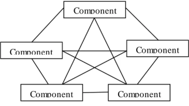
Direct connecting network: In Direct connecting network each network component is directly connected to every other network component.
Centralized network: In centralized network various network components are connected to centralized network component.
The network architecture comprises of five components. These are: 1) Terminal
2) Processors 3) Channels 4) Computers and 5) Control software
The three planes of the telecommunication network are:
1) Control plane: Control plane is associated with drawing the information or network map into the routing table.
2) Data plane: Data plane is associated of carrying the network’s user traffic and decides whether to keep the packet or discard the packet.
3) Management plane: Management plane manages the network and carries the administration traffic.
II.
TELECOMMUNICATION NETWIRK ARCHITECTURE
International Journal of Research in Engineering and Applied Sciences (IMPACT FACTOR – 6.573)
Figure 1: Telecommunication network architecture
The network described can either be packet switched or circuit switched. Each terminal in the network must contain an unique address so that the messages can be transmitted to that particular address. Following are the examples of network architecture:
1) Computer networks
2) Internet
3) Telephone networks.
Uses: Network architecture are used in management of GSM, ATM and ISON network.
A. Message and Protocols: Messages are transmitted through a network of links and nodes from the source terminal to the destination terminal. Messages consists of two parts:
1.) Control: control part is basically an instruction to transmit the message. 2.) Bearer: bearer part is actual message to be transmitted.
The control and bearer part can either be transmitted individually or together. The control and bearer parts are specified by using the protocols.
B. Types: There are two types of telecommunication network:
1.) Direct connect network: In direct network each component is directly connected to each other network component.
Figure 2: Direct Connect Network Disadvantages: The disadvantage of direct connection network are: 1.) Costly
2.) Complex
2.) Centralized network: In centralized network various network components are connected to centralized network component.
Figure 3: Centralized Network Component
1
Component 2
Component 5
Component 3
Component 4
Component 1 Component 4
Centralized Network Component
Component 2 Component 3
Link
International Journal of Research in Engineering and Applied Sciences (IMPACT FACTOR – 6.573)
C. Components of the Network Architecture: Telecommunication network constitute five components irrespective of their type and usage. The list is discribed as given below:
1.) Terminals: Terminals are starting or stopping points in a telecommunication network. These are basically used to transmit and receive data across network
2.) Processors: Processor provide ways for data transmission and reception between terminals with the help of support and control functions.
3.) Channels: These are the wires and cables through which the data is transmitted and received. For example: optical fibers, coaxial and copper wires etc.
4.) Computers: The computers are connected through the channels to perform data transmission.
5.) Control software: Control software is present on all networks computers and are responsible for controlling network[3] activities and functionality.
Channel
Figure 4: Components
D. Architecture: The architecture can be classified into three types:
1.) Control plane: These are also known as originating and are mainly concerned with drawing the information or network map into the routing table. Then it is the function of routing table to decide the action to be performed on the incoming packet. The information source that is to be routed can be configured either statically or dynamically.
2.) Data plane: these are also called the user plane or bearer plane. These carry the network’s user traffic and decide whether to keep the packet or discard the packet.
3.) Management plane: these are required for managing the network and carry the administration traffic.
E. Types of Telecommunication Network: the examples are listed below:
1.) Local area network: These connect computers and other devices within a limited and specified area with the help of wires and cables.
2.) Wide area network: These cover a large geographical area
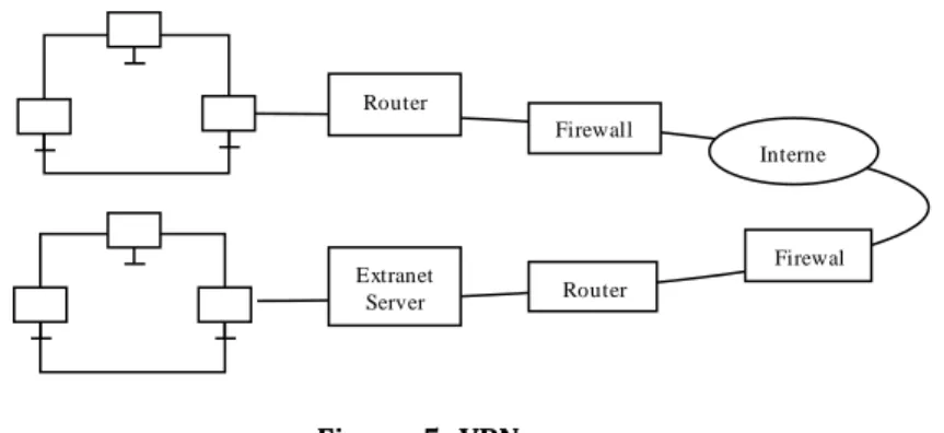
3.) Virtual private network: Virtual private network (VPN) depends upon firewall and a secure network that uses internet.
Figure 5: VPN
4.) Client/server network: Clients is the end user and server is associated with the processing of the application.
F. Further Classification of Architecture: The architecture can also be claasified as:
1.) Functional architecture: Functional architecture explains the functions of network management architecture. They identify a set of functional blocks and provide a way to transmit information and process the information about the various telecommunication services.
2.) Physical architecture: This is explaining how the function describe by the function architecture are actually implemented in the physical architecture. The Physical architecture implementation of TMN functional[4] blocks like network element, work station, adaptor operation system and data
Term inal
Processor Processor Com puter
Router
Extranet
Server Router
Firewal l Firewall
International Journal of Research in Engineering and Applied Sciences (IMPACT FACTOR – 6.573)
communication network is performed here. These functional blocks can also be implemented in a single block.
3.) Information Architecture: It explains the concepts adopted by the OSI (Open System Interconnection model) [5] and follows the object oriented approach. The managed object consists of three entities:
i. Attributes: These explain the properties of object.
ii. Operations: These operations are performed upon the object.
iii. Behavior: These particularly explain how an object behaves when a particular operation is performed upon the object.
4.) Logical Architecture: the management is divided into logical layers and group of functions. For example the manager of layer 1 is connected to the agent of the layer 2. The manager of layer 2 is connected to an agent of layer 3.
III.
TMN MANAGEMENT LAYERS
Definition: Telecommunication management network is a protocol described by ITU. This is used for managing open systems in a communication network. This is basically a framework which provides a means of interconnectivity and communication across a network. The TMN management layers can be grouped into four categories:
A. Business Management Layer
Business management layer: These covers the functions related to the business purpose. It analyses and focuses upon the quality issues related to network. The input of the business management layer is the service and element management layer. The business layer manages the entire enterprise with the help of strategic planning. This layer has a broader scope and relies on goal setting rather than achieving these goals.
Example: Employee satisfaction, Return on Investment.
B. Service Management Layer
Service management layer: The service management layer is responsible for managing the services that are to be provided to the customers. These mainly consider the aspects that are directly concerned with the users rather than physical entities. The input of the service management layer is the management information provided by the network management layer. This layer interacts with the service providers to provide services to the customer.
Example: Fault reporting, opening of a new account.
C. Network management Layer
Network management layer: These are responsible for managing various network elements and the functions which are related to interaction between multiple pieces of equipment in a communication network. These communicate with other management layers with the help of a standard interface.
The network, data analysis, data screening, and address translation.
D. Element Management Layer
The element management layer deals with the functions provided by vender to vender. The layer hides the functions from the layer above the network management layer and handles individual network elements. Examples:
a) Measuring power & resource consumption, b) Measuring temperature of equipments, c) Maintenance of hardware &software, d) Management of alarms,
e) Backup of data, f) Information handling.
E. Network Element Layer
The network element layer consists of network elements. This layer has three components:
1.) Managed device: this is a network node implementing SNMP interface. The access to this node can either be uni-directional or bi-directional.
International Journal of Research in Engineering and Applied Sciences (IMPACT FACTOR – 6.573)
3.) Network management system (NMS): NMS[6] executes the applications that monitors and controls the managed devices.
IV.
SIMPLE NETWORK MANAGEMENT PROTOCOL (SNMP)
Definition:
Simple network management protocol is a standard protocol that is used for managing the devices on the IP network. The devices that are managed and supported by SNMP are routers, switches, printer, modems etc. the protocol operates in the applications layer of the Internet Protocol Suite.
Protocol Data Unit (PDU): The following are the PDU: a) Get request
b) Set request c) Get next request d) Response e) Trap
f) Get-bulk request
A. SNMPV1
SNMPV1 is the initial implementation of the SNMP and Implements the community based security. SNMPV1 came into existence in 1998. SNMPV1 uses two protocols i.e. UDP and Internet Protocol.
Protocol Structure:
Figure 6: Protocol structure
PDU Type: PDU type specifies the type of protocol data unit to be transmitted. 0- Get request
1- Get Next Request 2- Get Response 3- Set Request
Request ID: It associates the number and type of error. Error Status: Indicates the number and types of error
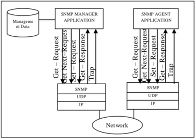
B. Architecture
Figure 7: SNMP Architecture
PDU Request Error Error Object 1 Object 2 ….. Type ID Status Index Value 1 Value 2
International Journal of Research in Engineering and Applied Sciences (IMPACT FACTOR – 6.573)
Entities: SNMP uses two types of entities, i.e., application and protocol entities. The application entities consist of network elements while the protocol entities consist of processes that support the application entities.
Disadvantages: a) Poor security
b) Limited performance c) Limited data types
C. SNMPV2
SNMPV2 is the evolution of SNMPV1. It uses the same operation as SNMPV1[6] except two new operations are added. The new operations added are:
a) GetBulk: This operation is used to retrieve large blocks of data.
b) Inform – Request: The network management system sends trap to another system and waits for the response.
Approach: SNMPV2 uses three approaches:
a) Management Information Base
b) Script Based
c) Remote Operation Based Protocol Structure:
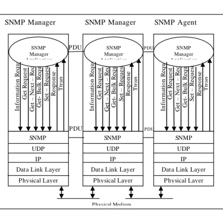
Figure 8: Protocol Structure
Figure 9: SNMPV2 Architecture
D. Improvements in the SNMPV2 Architecture:
The major improvement in the SNMPV2[7] over SNMPV1 is listed below: a) Bulk Data Transfer
b) Textual Conventions
c) Manager to Manager Message
PDU Request Error Error Object 1 Object 2 ….. Type ID Status Index Value 1 Value 2
SNMP Manager SNMP Manager SNMP Agent
PDU PDU
PDU PDU
P hysical Medium
In fo rm a ti o n R e q u e st G e t R e q u e st G e t – N e x t – R e q u e st G e B u lk R e q u e st S e t – R e q u e st R e sp o n se T tr a p SNMP UDP IP
Data Link Layer
Physical Layer SNMP Manager Application In fo rm a ti o n R e q u e st G e t R e q u e st G e t – N e x t – R e q u e st G e B u lk R e q u e st S e t – R e q u e st R e sp o n se T tr a p In fo rm a ti o n R e q u e st G e t R e q u e st G e t – N e x t – R e q u e st G e B u lk R e q u e st S e t – R e q u e st R e sp o n se T tr a p SNMP Manager Application SNMP Manager Application SNMP UDP IP
Data Link Layer
Physical Layer
SNMP
UDP
IP
Data Link Layer
International Journal of Research in Engineering and Applied Sciences (IMPACT FACTOR – 6.573)
Structure of management information: a) Module definitions
b) Object definitions c) Trap definitions Advantages:
a) Improved communication model
b) Greater security
c) Improved information model d) Additional error codes
E. SNMPV3
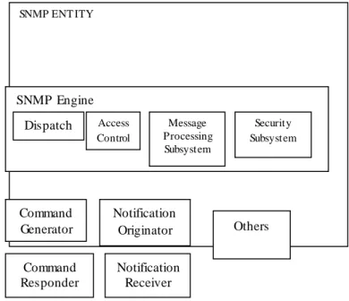
SNMPV3 provides a framework for all the versions of SNMP i.e., all the three versions can exist in a single management entity. The SNMPV3 document was published in 1998.
Architecture:
Figure 10: SNMPV3 Architecture
The architecture of SNMPV3 consists of many nodes and each node is associated with a SNMP entity. The nodes are used to interact and manage the network resources. The architecture of SNMPV3[8] is associated with naming of the entities, identities and management information.
a) Dispatcher
b) Message processing subsystems
c) Security and access control subsystems d) Application module
F. Applications of SNMPV3
a) Command generator
b) Command responder
c) Proxy forwarder
G. Threats
The security subsystem model is associated with the protection of SNMP against threats. Threats are: a) Modification of information
b) Masquerade
c) Message stream Change d) Traffic pattern analysis e) Disclosure
SNMP ENT ITY
APPLICATION
SNMP Engine Dispatch
er
Access Control
Message Processing Subsystem
Security Subsystem
Command Generator
Notification Originator
Command Responder
Notification Receiver
International Journal of Research in Engineering and Applied Sciences (IMPACT FACTOR – 6.573)
V.
REMOTE MONITORING (RMON)
Definition: The remote monitoring was developed by Remote Engineering task force to monitor the messages and to transmit the messages to a management station. The monitoring devices in a mangement station constitute of RMON software agents.
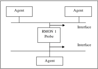
A. Architecturer
The data analyzes the SNMP traffic[9] and routes the data to the network management system with the help of a router. The SNMP traffic is then routed to the RMON probe which is associated with the LAN.
Advantages:
1.) No need for agents as in SNMP 2.) Less changes of Packet Loss. 3.) Reliable.
4.) High Network availability for the users.
B. RMON 1
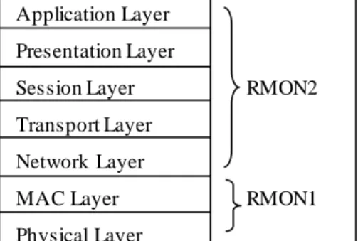
The RMON 1 covers the physical layer and MAC layer of OSI. RMON 1 is covered by RFC 1757 for Ethernet LAN and RFC 1513 for Token Ring LAN.
Figure 11: ISO Model
C. RMON 1 Data Types
The data ype used by RMON 1 is owner string and entry status. The owner string is defined by the owner string data type and entry status is used to solve the disputes that occur between the management systems.
The entry status data type exixts in four states. These are valid, invalid, create request and under-creation.
D. RMON 1 Group and Functions
The functions and groups of RMON 1 [10] are performed at the data link layer.
1.) Statistics: These contain statistics which are measured by the RMON probe for the interface on the device.
2.) History: History collects the statistical data and stores the data so that they can be retieved later. 3.) Alarm: Generates statistical samples and compares these samples with threshold that are
pre-established.
4.) Host: These contain statistics which are associated with each host parent on the network. 5.) Top N Hosts: Define tables that computes the top N hosts.
6.) Matrix: Gather statistics on traffic in between pair of hosts. These statistics are stored so that they can be retrieved later.
7.) Filter: These perform filter functions to capture events.
8.) Packet Capture: Packets can be captured after they flow through a channel. 9.) Events: Controls the generation and notification of events.
10.) Token Ring: These are not used much and support the token ring. Application Layer
Presentation Layer
Session Layer RMON2
Transport Layer Network Layer
MAC Layer RMON1
International Journal of Research in Engineering and Applied Sciences (IMPACT FACTOR – 6.573)
Figure 12: RMON 1 Probe interface
E. Types of Statistics The RMON 1 statistics are:
1.) Token ring Statistics: These consist of token ring history. 2.) Ethernet statistics: These consist of Ethernet history.
3.) Host statistics: These consist of host and top N host statistics.
F. RMON 2
RMON 2 monitors all the higher layers of RMON 1. These provide similar functions as RMON 1 and analyses the data traffic in a more accurate manner.
a) Capabilities Improved filtering Higher layer statistics. b) Advantages
1.) Fast debugging.
2.) Shows the network manager who is talking to whom. 3.) High performance
4.) Accurate traffic analysis c) Disadvantages
1.) Data mapping is difficult
G. RMON 2 Groups and Functions
1.) Protocol Directory: This is used when the application and agent belongs to different vendors. This is an inventory of protocols.
2.) Protocol Distribution: the octent of data is mapped to correct protocol and displayed to the network manager.
3.) Address Mapping: Address translation is carried between the MAC and network layer address. These are easier to read and remember.
4.) Network Layer Host: The traffic data from and to the network hosts. 5.) Network Layer Matrix:Traffic data from each pair of hosts.
6.) Application layer host: Traffic data by protocol from and to each host. 7.) User History: It constitutes user specified history.
8.) Probe Configuration: Remote configuration of another vendor’s RMON Probe.
VI.
ACKNOWLEDGMENT
Nobody can do anything without the grace of God. I first thank to “Lord Krishna” and “OMKAR” who blessed me to achieve my ambition by writing this research paper named “Security: Telecommunication and Network Architecture”.
Interface
Interface
Agent Agent
Agent RMON 1
International Journal of Research in Engineering and Applied Sciences (IMPACT FACTOR – 6.573)
I also thank to my husband, my children, my in-laws and my parents who supported me for accomplishing my goal.
I would also like to thank my friends and my colleague who supported me in each step. I would like to thank my publishers who gave me the golden opportunity to write this research paper.
VII.
REFERENCES
[1] Eason, B. Noble, and I. N. Sneddon, “On certain integrals of Lipschitz-Hankel type involving products of
Bessel functions,” Phil. Trans. Roy. Soc. London, vol. A247, pp. 529–551, April 1955.
[2] J. Clerk Maxwell, A Treatise on Electricity and Magnetism, 3rd ed., vol. 2. Oxford: Clarendon, 1892, pp.68–73.
[3] I. S. Jacobs and C. P. Bean, “Fine particles, thin films and exchange anisotropy,” in Magnetism, vol. III, G. T.
Rado and H. Suhl, Eds. New York: Academic, 1963, pp. 271–350.
[4] K. Elissa, “Title of paper if known,” unpublished.
[5] R. Nicole, “Title of paper with only first word capitalized,” J. Name Stand. Abbrev., in press.
[6] Y. Yorozu, M. Hirano, K. Oka, and Y. Tagawa, “Electron spectroscopy studies on magneto-optical media and
plastic substrate interface,” IEEE Transl. J. Magn. Japan, vol. 2, pp. 740–741, August 1987 [Digests 9th Annual Conf. Magnetics Japan, p. 301, 1982].
[7] M. Young, The Technical Writer’s Handbook. Mill Valley, CA: University Science, 1989.
[8] Electronic Publication: Digital Object Identifiers (DOIs):
[9] D. Kornack and P. Rakic, “Cell Proliferation without Neurogenesis in Adult Primate Neocortex,” Science, vol.
294, Dec. 2001, pp. 2127-2130, doi:10.1126/science.1065467. (Article in a journal)
[10] H. Goto, Y. Hasegawa, and M. Tanaka, “Efficient Scheduling Focusing on the Duality of MPL Representatives,”