1
Modeling Pilot Pulse Control
Edward BachelderSan Jose State University
U.S. Army Aviation Development Directorate Moffett Field, California 94035
Ronald Hess Martine Godfroy-Cooper Bimal Aponso University of California, Davis San Jose State University NASA Ames Research Center Mechanical & Aerospace Engineering NASA Ames Research Center Moffett Field, California 94035 Davis, California 95616 Moffett Field, California 94035
Abstract. In this study, behavioral models are developed that closely reproduced pulsive control re-sponse of two pilots from the experimental pool using markedly different control techniques (styles) while conducting a tracking task. An intriguing find was that the pilots appeared to: 1) produce a continuous, inter-nally-generated stick signal that they integrated in time; 2) integrate the actual stick position; and 3) compare the two integrations to issue and cease pulse commands. This suggests that the pilots utilized kinesthetic feedback in order to perceive and integrate stick position, supporting the hypothesis that pilots can access and employ the proprioceptive inner feedback loop proposed by Hess’ pilot Structural Model [1]. The Pulse Models used in conjunction with the pilot Structural Model closely recreated the pilot data both in the fre-quency and time domains during closed-loop simulation. This indicates that for the range of tasks and control styles encountered, the models captured the fundamental mechanisms governing pulsive and control pro-cesses. The pilot Pulse Models give important insight for the amount of remnant (stick output uncorrelated with the forcing function) that arises from nonlinear pilot technique, and for the remaining remnant arising from different sources unrelated to tracking control (i.e. neuromuscular tremor, allocation of cognitive re-sources, etc.).
1
INTRODUCTION
The earliest study of the human operator as a linear servomechanism is that of Tustin [2] who proposed that, despite amplitude nonlinearities, temporal discontinuities and haphazard fluctua-tions, there might be an “appropriate linear law” that would describe the main part of the operator’s behavior. Insight from servomechanical design led McRuer and Krendel [3] to develop the ubiquitous human Crossover Model (CM), which within its framework accounts for how, and why, the human operator adapts to the controlled plant dynamics during compensatory tracking. With the crossover model, a variable pilot time delay can be used to explain phenomena such as increased high-frequency phase lag associated with increased amounts of error lead equalization. Similarly, ratchet (sustained high frequency, small amplitude pilot-vehicle system oscillations) can be ascribed to variable neuromuscular damping (first proposed by Johnston and McRuer in 1987 [4], and later investigated by Bachelder in 2003 [5] using
wave-lets). In 1976 Smith [6] propounded that inner-loop rate feedback supported control of the error loop during compensatory tracking, whereby the rate of the controlled system’s output was visually per-ceived by the operator. This manner of feedback was subject to two key constraints: 1) the band-width and noise associated with human visual sensing of rate, and 2) the requirement that the ratio of disturbance-to-system output is low, oth-erwise the error rate that the operator perceives will not correspond to system output rate. A real-izable method for perceiving rate for use with in-ner-loop feedback was first posed by Hess in 1978 [7], whereby the operator employs kinesthet-ic perception of control rate and an internal model of system response to that rate. This approach was later incorporated into Hess’ Structural Model of the human pilot [1,8]. In 1969 Gaines [9] wrote “Models capable of representing behavior over large domains are particularly important in the study of learning systems where the mode of
2
havior is expected to vary widely with experience. A variety of models is required, and within the modeling schemata there must be scope for a sufficient variety to provide adequate matches during all phases of learning.” Building on Krendel and McRuer’s [10] successive organization of perception (SOP) model for tracking skill devel-opment, Hess’ pilot Structural Model provides a concise, integrated architecture for describing compensatory, pursuit, precognitive, and off-nominal behavior.
The work presented here extends Hess’ Struc-tural Model to account for and reproduce pilot compensatory behavior when different control styles are used. It lays the groundwork to explore how pilot control technique (i.e. pulsive versus continuous) influences the interplay between in-ternal costing and the nominal values of a param-eter set that defines pilot behavior.
2.
STRUCTURAL MODEL OF THE
HUMAN PILOT
In 1978 Hess [7] proposed a model (see Fig. 1) for human compensatory tracking whose es-sential features included an outer loop operating on error (e), an inner loop feedback operating on stick position (δ), pilot elements that equalize the error and stick signals (respectively
Yp
e,Yp
m), a pilot elementYp
n generating the neuromuscular force of the particular limb which drives the ma-nipulator, the manipulator dynamicsY
that pro-duces the control system input (usually stick dis-placement) from the force command, a controlled elementY
c representing the vehicle dynamics, and the display elementY
d that transforms the physical system error to the visually displayed error being tracked. A disturbance d is added to the vehicle output m, and the negative of this is the error that the operator is attempting to null.According to McRuer and Krendel [3] the neu-romuscular element can be approximated by Eqn (1), where
n and
n represent the natural fre-quency and damping ratio, respectively.(1) ) 2 2 ( 2 2 n n n n n s Yp
With the inner loop of Fig. 1 closed, the simple quadratic form for
Yp
n can exhibit the key fea-tures of measured high-frequency humancontrol-ler dynamics, namely, a typically subcritical damp-ing ratio
n
CL, and a minimum second-order am-plitude fall-off beyond the undamped natural fre-quency
n
CL. The injected remnant signal ne is included to account for nonlinearities and/or time variations in quasilinear fashion.Fig. 1. Quasilinear dual-loop model of the human controller [7].
Typically, the main function of the inner-loop is to provide vehicle output rate feedback and im-prove stability and precision. Hess proposed (see Fig. 1) that the neuromuscular force output is per-ceived and transformed into an estimate of vehicle output rate using an internal model of the manipu-lator and vehicle dynamics suite. For acceleration command dynamics, this process effectively re-quires the pilot to integrate the force output (in the dual-loop model shown the pilot first perceives the force rate, and integrates this twice). Hess hy-pothesized that proportional or derivative control in the feedback loop can be conducted using di-rect information from the muscle spindles and Golgi tendon organs [11], but integral control does not have analogous information and requires the operation to employ higher level cognitive pro-cessing [7]. Thus when controlling acceleration command systems, the pilot will tend to generate a pulsive force output rather than a continuous one, since a pulse is the least difficult of all wave-forms to integrate (an impulse is even easier, but is a variation of the pulse). While the pulse is held, the system response is the inverse Laplace trans-form (L-1) of the integral of the vehicle dynamics (for acceleration command system, this would be
L-1(K/s3)). Following the pulse, the system re-sponse is simply the inverse Laplace transform of the vehicle dynamics, L-1(K/s2). "Ease of integra-bility" can be generally interpreted in a physiologi-cal sense as applying to those waveforms whose integration requires a minimum of higher-level activity in the central nervous system [12].
As an operator becomes familiar (gains exper-tise) with the vehicle and manipulator, the trans-formation between force output and vehicle output rate should reduce to a one-step process. In his
3 revised Structural Model [1], Hess reflects this simplification with a proprioceptive feedback ele-ment,
Y
PF, shown in Fig. 2. This element receives stick position (δM), and depending on the vehicle dynamics in the vicinity of the crossover frequen-cy,Y
PF will assume one of the forms shown in Table 1 (to approximately generateM
, the rate of the output). The vehicle dynamics in Table 1 are position, rate, and acceleration command, respec-tively, and the correspondingY
PF is a first-order lead, proportional, and first-order lag, respectively. Table 1. Proprioceptive feedback element YPF form.In manual control theory, proprioception refers to the monitoring of body’s actions– excluding the
visual and vestibular systems. The kinesthetic system is a subsystem of the proprioceptive sys-tem, dedicated to the perception of position and movement. In this paper proprioceptive and kines-thetic input will be used interchangeably. A gain
e
K
serves as the pilot element acting on error, and the neuromuscular and feel system elements are respectively denoted byY
NM andY
FS. Note thatY
NM in Fig. 2 isYp
n in Fig. 1. While the vari-ous other details of the Structural Model (Fig. 2) are described in [1], an element of key importance is the central processing time delay
o, which for a given pilot is approximated as vehicle-invariant. This represents a major simplification to the crossover model’s effective time delay, which was used to explain (but could not predict) task and vehicle-dependent high frequency phase loss.Fig. 2. Structural Model of the Human Pilot [13]. Fig. 3 reduces the Structural Model to the
components relevant for fixed-base compensatory control (hence the vestibular paths are removed), with two modifications. The pilot element operat-ing on the error channel is now represented by
Y
e, and a pilot elementY
TECHhas been added just prior toY
NM. Hess employed a similar element in his Dual Loop model [12] to account for pulsive response. In Fig. 3,Y
e appears as a first-orderlead instead of the pure gain of Fig. 2. - this form allows more adaptive error equalization, and it is seen in earlier versions of the Structural Model.
TECH
Y
represents the logic generating a pilot’snon-linear control technique, which can be a set of conditionals and the supporting computations. The vehicle dynamics used in the following exam-ple cases will either be acceleration or jerk com-mand dynamics, consequently
Y
PF for both will be a first-order lag (see Table 1).4
Fig. 3. Pilot Structural Model simplified for fixed-base tracking.
3
WORKLOAD EXPERIMENT
An experiment was conducted that investigat-ed the relationship between aircraft input/output states and pilot workload. Four command vehicle dynamics (proportional, rate, acceleration, jerk), vehicle gains (vehicle sensitivity to input), and display gains (display sensitivity to error) were used with a lateral station-keeping using a com-pensatory display, where a random forcing func-tion continuously disturbed ownship’s posifunc-tion.
Fig. 4a shows a representation of the station-keeping task and the display (KD), pilot (YP) and vehicle (YV) components of the closed-loop
sys-tem. Fig. 4b gives the range of conditions within each component that were tested. The jerk condi-tion for the vehicle dynamics (fourth condicondi-tion listed for YV), contains a pole p whose location was varied. Twenty-three display configurations were tested with each subject using various com-binations of the conditions shown in Fig. 4b. The configurations were selected to maximally span the Bedford rating over all vehicle command dy-namics. Since pilot proficiency with any test condi-tion was not a factor in this experiment, pilots were given two practice of each vehicle dynamic type (proportional, rate, acceleration, jerk) prior to testing.
Fig. 4. Station-keeping task. a) Pilot, display, and vehicle elements; b) Range of conditions for display and vehicle el-ements. + --d e δ y P
Y
Y
V Pilot Vehicle DK
Display e D a. b. V Y 2 , s KV , s KV , V K 2 ) (s ps KV
5 ,10,30,60
V K p
1 ,2,5
0.5 ,2,4,8,32
D K5 One may be tempted to think that the display gain and the vehicle gain are effectively inter-changeable and the same gains from the pilot’s vantage point. The following example will serve to disprove this common misnomer. If the pilot’s in-put is zero, the disturbance is perceived through the display gain – the vehicle gain does not come into play at all. Based on his/her control activity and quiescence, a pilot learns to decouple the effects of the display gain from the vehicle gain – thus decoupling aircraft motion due to disturbance from pilot-commanded vehicle motion.
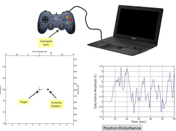
Four male participants took part in the study. Three were Experimental Test Pilots (graduates of Navy Test Pilot School) with 1,900, 1,900, and 2,450 rotary wing flight hours. The fourth partici-pant had logged 800 hours of rotary wing flight time. Ownship error relative to the target location was displayed on a laptop monitor (see Fig. 5), and the pilot attempted to minimize the error using a gamepad joystick (Logitech Dual Action gamepad). The Bedford rating scale [14] was used to subjectively score each pilots spare ca-pacity at the end of each 60-second tracking run. Dependent qualitative variables were: stick
posi-tion, rate and acceleraposi-tion, stick position rever-sals, display error, rate, and acceleration. The positional disturbances imposed on the helicopter were designed to be both realistic and a diagnos-tic probe for pilot control behavior. Composed of a sum of 11 non-harmonically-related sine waves, the disturbance was perceived by the pilot as a random process – the result, however, was that the pilot’s control response power resided largely at the same frequencies contained in the input disturbances. Sum-of-sines (SOS) is a standard approach that has been employed by the manual control research community over many decades. The disturbance time history is shown in Fig. 5 (it ranged from approximately -1 to 3 feet, with a standard deviation of 1 foot). The results of the experiment are given in [15].
The damped frequency of the gamepad joy-stick was approximately 200 rad/sec, well above the neuromuscular mode. Thus the feel system
FS
Y
in Fig. 3 can be considered unity for this ex-periment.6
4
PULSIVE MODEL DEVELOPMENT
In the experiment two pilots were observed to use different pulse techniques when controlling the acceleration and jerk command dynamics. Fig. 6a shows the pulse width modulation (PWM) technique, where the gamepad joystick was rapid-ly deflected to the stops and released, so that
pulse firing and pulse width were predominantly the only two control variables. In digital control PWM creates a square wave, a signal switched between on and off, to create analog results with digital means. Fig. 6b shows the pulse width-amplitude modulation (PWAM) technique (coined by the author), where stick motion consists of pulses for motion that reaches the stops, and am-plitude-varying impulses otherwise.
Fig. 6. Pilot control techniques used in tracking task. a) Pulse width modulation; b) Pulse width-amplitude modulation. At the time that the pulse models were developed
the CM was used to characterize the pilot ele-ment. Both the Structural Model and the CM yield equivalent frequency responses for the pilot (δ/e in Fig. 7a) in the region of crossover frequency ωc [7]. The following describes the procedure that was employed to recognize and formulate the pulse logic for both the PWM and PWAM tech-niques. The open loop frequency response (y/e in Fig. 7a) was computed, from which the ωc and the effective time delay
were estimated. Assuming the pilot acts like a first-order lead with a time de-lay (see Yp in Fig. 7a), when crossover occurs K can be written in terms of known constants and the unknown lead term TL. This is substituted backinto Yp so that the only unknown is TL, and a best-fit is performed (solid blue line in Fig. 7b) with pilot’s magnitude and phase (filled circles in Fig. 7b) to yield TL, hence Yp. The output of Yp is termed the CM stick response, and this was com-puted in time over the run and compared with the actual stick pulses (Fig. 7c). It was observed that in general a pulse is triggered by zero-crossings and opening speed reversals (i.e. away from zero) in the CM stick response. Fig. 7c also shows a pulse that does not correlate with either a zero crossing or an opening speed reversal, and this kind of pulse occurred often enough to warrant examining its trigger source.
7
Fig. 7. CM employment for PWM logic identification. a) Basic CM elements; b) Identified pilot frequency response for PWM technique; c) CM stick signal overlaid on actual stick history showing correspondence between pulsing and CM’s stick signal.
In Fig. 8b the areas under actual and crosso-ver stick signals are integrated in time, with inte-gration starting and ending when the sticks change polarity. It is seen that the integrations approximately match when the stick polarities flip. By inspection pulses were observed to obey the logic shown at top of Fig. 8, where a pulse ceases if the area under the actual stick is greater than some fixed percentage of the area under the crossover model’s signal. Pulses are triggered when the crossover model’s stick encounters a zero crossing or opening speed reversal, or when the area under the actual stick is less than some fixed percentage of the area under the crossover model’s signal. It was also observed that there is generally consistent a delay between when a zero crossing or opening speed reversal occurs, and
when a pulse is actually triggered. This appears to be a safeguard against spurious triggering by re-quiring a certain amount of time to pass and for the amplitude to rise above some minimum threshold before the operator commits to a pulse.
The logic governing PWAM was similar to PWM, except that the variable pulse amplitude was assigned to be the CM’s stick amplitude at the time of pulse trigger, multiplied by a constant. Fig. 9 compares the modeled and actual stick outputs for the PWM and PWAM styles, and they subjectively appear to agree well. In the next sec-tion, modeled and actual behavior will be com-pared using frequency response, as well as prob-ability distributions of the stick amplitude and peri-ods of stick inactivity (quiescence).
8
Fig. 8. PWM Crossover Model and stick integration. a) CM stick signal overlaid on actual stick; b) Comparison CM in-tegration and actual stick inin-tegration (they are roughly equal at each zero crossing of the CM output). Pulse logic shown at top, governing pulse width and pulses not associated with zero crossing and opening speed reversal.
Fig. 9. Comparison of pulse models with actual data: a) Pulse Width Modulation; b) Pulse Width Amplitude Modula-tion.
5
MODEL VERIFICATION
Bachelder and Aponso [15] identified a nonlin-ear pilot control technique termed ‘amplitude clip-ping,’ whereby the pilot responds to error as pre-dicted by the CM up to a certain stick amplitude and then holds that amplitude until the error signal reverses and returns, at which time the pilot
re-sumes active continuous tracking. The amplitude at which the control input is capped can vary over time. Examples are now given where Structural Model was used to identify the pilot element for the PWM, PWAM, and amplitude clipping control techniques.
Rather than iterate on the undamped natural frequency of the open loop neuromuscular system (ωNM) along with the other parameters of the
9 Structural Model (Fig. 3) until a best-fit with the observed data is obtained (or fixing ωNM at some assumed value), the power spectrum of pilot’s stick was examined. Fig. 10a shows the power spectrum density (PSD) of the stick when ampli-tude clipping was used to control acceleration command dynamics. The frequencies of the SOS forcing function are denoted with open circles, the highest frequency located approximately at 5 rad/sec. Fig. 10b is a close-up beyond 5 rad/sec, and power can be observed up to about 10 rad/sec, showing a concentration at around 7
rad/sec. When jerk-command dynamics are con-trolled (again using amplitude clipping), Fig. 10d shows the power to be more evenly distributed between 5 and 10 rad/sec. Based on these obser-vations, ωNM was fixed at 8 rad/sec when ampli-tude clipping was used as the control style. This is lower than the value used by Hess in [8], which is likely due to the different inceptor and limb char-acteristics (the gamepad joystick is controlled by the thumb).
Fig. 10. Spectral decomposition of stick response: a) Using acceleration-command vehicle dynamics (forcing function power denoted by open circles); b) Close-up beyond the forcing function power. c) Using jerk-command vehicle dynam-ics; b) Close-up beyond the forcing function power.
Using the delay employed in [8], the pilot time delay was fixed at 0.20 seconds, and the five oth-er parametoth-ers of the pilot Structural Model (Ke, TL, Kδ, TK, ϛNM) were iterated in a Simulink model of Fig. 3 to minimize the cost function J given in Eqn. 2. (2) ] * ) ( * * * * * [ 4 3 8 1 2 8 1 1 8 1 2 8 1 1 PDF phs mag phs mag J i Yp i i Yp i i YpYv i i YpYv i
In Eqn 2, Δ( ) refers to the absolute difference between observed and simulated variable ( ).
YpYv i
mag
10 open loop magnitudes (YpYv , in dB) between observed and simulated at each frequency i of the forcing function,
phs
iYpYv denotes the difference in the open loop phase, and
mag
iYpandYp i
phs
use the magnitude and phase of the pilot element, respectively.
(
) is the standard devia-tion of the stick, and PDF is the probability density function of the stick amplitude (see Fig. 13a). The elements in Eqn 2 are weighted by constants
. The time domain metrics (σ and PDF) were in-cluded since it is possible for a very different stick power distribution and σ to produce the same frequency response.Four runs from the workload experiment are used to examine the pilot models. Three runs use the same display, stick, and vehicle dynamics (vehicle is acceleration-command), and are flown by three different pilots: one employing the PWM technique, the second PWAM, and the third ampli-tude clipping (AC). The fourth run used AC and jerk-command dynamics, flown by the same pilot who employed AC with acceleration-command dynamics. These four runs were selected to high-light differences due to techniques and vehicle dynamics. The parameters minimizing the cost function for four simulation runs are given in Table 2, along with various metrics. The estimated Bed-ford rating (computed from the modeled response as described in [15]), Best, and the actual Bedford rating are given in Table 2. Also compared is the
relative correlated output ρ2, defined as the por-tion of the power in the stick output which exists at the disturbance frequencies, divided by the total stick power. For instance, in Fig. 10a, summing the areas flanking each forcing frequency (out to the first local minimum in PSD) yields the corre-lated power, and this is divided by the total PSD area.
Fig. 11 shows the identified open loop and pilot frequency responses (computed using cross spectral densities, [3]) from the observed pilot data and from the data generated by the nonlinear simulation (nonlinear due to the pilot technique element YTECH). This example employed accelera-tion-command dynamics, and the pilot technique was amplitude clipping. The solid line denotes the linear frequency response produced without the nonlinear pilot technique element. The nonlinear effects of clipping are minimal except at the lower frequencies, where magnitude is reduced.
Looking at Table 2 the relative correlated out-put ρ2 for the simulation is 0.93, also reflecting the technique’s minimal impact on remnant. Note that the actual value of ρ2 was 0.85, suggesting that the pilot’s contribution to remnant due to internally generated noise is approximately 8% (0.93-0.85) of the total stick power. Without an accurate mod-el of pilot technique, the 15% total remnant ob-served from the pilot data could not have been partitioned into technique and internal noise.
Table 2. Pilot model parameter values used to generate describing functions, and comparison of simulated and actual measures.
11 Fig. 12 shows good correspondence between the time histories of the actual and simulated stick amplitudes. Actual and simulated stick PDFs compare favorably in Fig. 13a, as does the distri-bution of quiescence time in Fig. 13b. Quiescence was defined as when the stick’s rate fell below a threshold, when stick amplitudes were non-zero (i.e. time did not accrue towards quiescence when the stick was in the zero-force, zero-amplitude
position). The metrics for this run in Table 2 (K/s2 dynamics, AC denotes amplitude clipping), in combination with Fig. 11 - Fig. 13, indicate that the integrated components of the model repro-duced the pilot’s response with high accuracy. Of note is that the pilot did not employ the kinesthetic feedback loop (Kδ was zero), instead equalizing the error channel with only gain and lead.
Fig. 11. Identified open loop and pilot frequency responses for the pilot data and nonlinear model data, with the linear model overlaid (acceleration-command dynamics, Amplitude-Clipping model). Note the difference in scale between Open Loop and Pilot responses.
12
Fig. 13. Distributions for stick associated with Fig. 12 comparing actual and model: a) Stick amplitude distribution; b) Stick quiescence distribution.
Simulation of the control style PWAM in the Structural Model is now examined. The sharp edges and corners observed in the stick response for both PWM and PWAM control infer that their neuromuscular dynamics affected frequencies far higher than what was measured when amplitude clipping (pseudo-continuous) control is used. When the joystick stops are reached (+/- 100%) the neuromuscular mode does not factor at all. The neuromuscular pilot element YNM was thus set to unity when modeling PWM and PWAM, eliminating ωNM and ζNM from the identification process. Fig. 14 shows good model agreement with the actual frequency and time responses. The linear response (i.e. when the pilot technique element is left out) in Fig. 14b illustrates how high-fidelity modeling can expose observed measure-ments as artifacts of technique rather than the result of internal processing. McRuer [3] describes the phenomenon of low frequency ‘droop’ ob-served in pilots, which was not accounted for by the basic CM. This low frequency phase loss in-creased with the order of the system being con-trolled, and in [7] was attributed to and reproduced using the inner kinesthetic feedback loop. Howev-er, in this run the marked difference in phase (and magnitude) between the linear response and the nonlinear response at the lowest frequency is due entirely due to the PWAM technique. If the
kines-thetic feedback were contributing to the phase and magnitude droop this would have caused the linear response to move toward the modeled non-linear response. The actual measured phase agrees with the nonlinear model, including at the higher frequencies where the pilot phase also departs from the linear response. Phase droop also occurs with rate and position command dy-namics [3], where continuous control would cer-tainly be employed and technique would not be a factor, but this example highlights the potential importance of including pilot technique when as-signing causality.
Looking at Table 2, the pilot made substantial use of inner-loop proprioceptive feedback (Kδ = 0.25), and remnant due to technique (1- ρ2sim = 24%) was considerably larger than when ampli-tude clipping was employed by the other pilot (where 1- ρ2sim = 7%). Despite the seemingly sto-chastic nature of PWAM, the pilot’s internal rem-nant (4%) was half the internal noise associated with the amplitude clipping technique. This is quite remarkable given that the pilot appears to be sim-ultaneously integrating both the physical stick position as well as the internally-generated stick position to generate the pulse commands (see Fig. 8).
13
Fig. 14. Pulse Width Amplitude Modulation (acceleration command dynamics): a) Comparison of actual and simulated stick; b) Frequency response comparison of open-loop; c) Stick amplitude distribution; d) Stick quiescence distribution.
The frequency and time domain results in Fig. 15 show excellent correspondence between mod-eled and pilot data for PWM control. The simulat-ed PWM control technique producsimulat-ed 33% rem-nant, and since this coincided with the remnant observed in the experimental data then the pilot apparently generated almost no internal noise
(given the model’s accuracy). The technique also appears to be responsible for the leveling of mag-nitude at the higher frequencies (note the ob-served and nonlinear model magnitudes match, departing from the linear response in Fig. 15). Kinesthetic feedback was activated (Kδ =0.10), but to a lesser extent than with PWAM.
14
Fig. 15. Pulse Width Modulation (acceleration command dynamics): a) Comparison of actual and simulated stick; b) Frequency response comparison of open-loop; c) Stick amplitude distribution; d) Stick quiescence distribution.
The last example examines a run that em-ployed amplitude clipping to control jerk dynamics - dynamics which are extremely challenging to stabilize and to conduct tracking with. In Fig. 16 the model produced a good match with the pilot data in frequency response and stick amplitude distribution, and a fair match in the time response and quiescence distribution. The internal noise (ρ2sim - ρ2act) of the pilot is the highest (11%) out of the four runs presented, and in contrast to when this pilot was controlling acceleration command dynamics, he now employed proprioceptive feed-back (Kδ = 0.10) and generated the largest lag time constant (TK=1.13, more than double what the other two pilots operated at).
With the evidence suggesting that both PWM and PWAM integrate the internal stick signal and the physical stick position (Fig. 8b), the Structural Model has been modified (Fig. 17) with technique-dependent switches that can enable the integra-tion paths to the pilot technique element when needed. Since the two pulsive techniques re-quired pure kinesthetic integration of the stick, it seems reasonable to assume that this same in-formation would be employed by the first-order lag in the kinesthetic feedback loop (see YPF in Fig. 3). Coincidentally PWM and PWAM were both observed to employ this loop.
15
Fig. 16. Amplitude Clipping (jerk command dynamics): a) Comparison of actual and simulated stick; b) Frequency re-sponse comparison of open-loop; c) Stick amplitude distribution; d) Stick quiescence distribution.
Fig. 17. Pilot Structural Model showing integration of internal stick and physical stick signals as technique-dependent inputs to the pilot technique element.
16
6
CONCLUSIONS
Two models representing two types of ob-served pilot pulsive behavior – pulse width modu-lation (PWM), and pulse width amplitude modula-tion (PWAM) – were developed. These two pul-sive models and a third nonlinear model (ampli-tude-clipped continuous control) were analyzed using pilot data Hess’ pilot Structural Model. Pre-liminary results suggest:
1) The pulsive models used in conjunction with the pilot Structural Model closely re-produced the pilot data both in the fre-quency and time domains during closed-loop simulation. This suggests that for the range of tasks and control styles encoun-tered, the models captured the fundamen-tal mechanisms governing pulsive and control processes.
2) Pulsing can produce artifacts such as low frequency droop that may appear as char-acteristics internal to the pilot when they are the result of control technique. Accu-rate modeling can identify such artifacts. 3) The pulse models developed give
im-portant insight for the amount of remnant (stick output uncorrelated with the forcing function) that arises from nonlinear pilot technique, and for the remaining remnant arising from different sources unrelated to tracking control (i.e. neuromuscular tremor, etc.).
4) In addition to emulating observed pilot be-havior, the pilot Structural Model provides a method of economy for modeling higher frequency response. By assuming an in-variant pilot time delay and neuromuscular damping, and using the stick power spec-trum to estimate the neuromuscular natural frequency, kinesthetic feedback systemati-cally emulated high frequency phase loss. In contrast, the single-loop CM accounts for this phase loss using an effective time delay, which is roughly attributed to in-creased level of difficulty.
5) During pulsive control of K/s2 (acceleration command) vehicle dynamics, it appears that skilled pilots: 1) produce a continuous, internally-generated stick signal that they integrated in time; 2) integrate the actual stick position; and 3) compare the two in-tegrations to issue or cease a pulse com-mand. Since the two pulsive techniques (PWM and PWAM) required pure kines-thetic integration of the stick, it seems rea-sonable to assume that this same infor-mation could be employed by the first-order lag in the kinesthetic feedback loop. Both pulsive techniques were observed to use this loop.
6) The pilot employing PWM rapidly deflected the gamepad’s joystick to the stops (i.e. maximum deflection), producing sharply-edged and cornered pulses. The PWAM style employed both this technique and a train of spikes, where the stick impulsively rose to some peak amplitude and rapidly return to zero when released. The best matching between the modeled and ob-served behavior (PWM and PWAM) was obtained by setting the neuromuscular pilot element YNM to unity, implying that those techniques were largely unaffected by the neuromuscular constraints typically asso-ciated with manual tracking. Thus pulsing can present a method for ameliorating un-favorable stick characteristics.
The cases explored in this study are too few to offer statistically significant results, rather they are intended to provide insight and guidance for future research.
Acknowledgments
This work was supported by cooperative agreement NNX16AJ91A between the U.S. Army Aviation De-velopment Directorate and San Jose State University. This paper has been approved for public release: un-limited distribution.
REFERENCES
1 Hess, R. A., "Unified Theory for Aircraft Handling Qualities and Adverse Aircraft-Pilot Coupling", Journal of Guid-ance, Control, and Dynamics, Vol. 20, No. 6, 1997.
17
2 Tustin, A., “The nature of the human operators response in manual control and its implication for controller design,” J. Instn. Elect. Engrs, 94, 190, 1947.
3 McRuer, D. T. and Krendel, E. S., “Mathematical Models of Human Pilot Behavior," No. AGARDograph No. 188, November 1973.
4 Johnston, D.E., and McRuer, D. T., "Investigation of Limb-Side Stick Dynamic Interaction with Roll Control," Journal of Guidance, Control, and Dynamics, Vol 10, No 2, March-April 1987, pp 178-186.
5 Bachelder, E. N., and Klyde, D. H., “Wavelet-Based Analysis of Roll Ratchet Using a Flight Test Database,” AIAA 2003-5692 presented at AIAA Atmospheric Flight Mechanics Conference, Austin, TX, August 11-14, 2003.
6 Smith, R. H., "A Unified Theory for Pilot Opinion Rating, "Proceedings of the Twelfth Annual Conference on Manual Control, May 1976, pp. 542-558.
7 R. A. Hess, "A Dual-Loop Model of the Human Controller," Journal of Guidance, Control, and Dynamics, vol. 1, pp. 254-260, July-Aug. 1978.
8 Hess, R. A., "Pursuit Tracking and Higher Levels of Skill Development in the Human Pilot”, IEEE Transactions on Systems, Man, and Cybernetics, Volume: 11, Issue: 4, April 1981.
9 Gaines, B., “Linear and Nonlinear Models of the Human Controller,” International Journal of Man-Machine Studies (1969) 1, 333-360.
10 Krendel, E. S., and McRuer, D. T., "A servomechanisms approach to skill development," J. Franklin Inst., vol. 269, pp. 24-42, Jan. 1960.
11 McRuer, D. T., A Neuromuscular Actuation System Model, IEEE Transactions on Man-Machine Systems, vol. MMS-9, no. 3, September 1968.
12 Hess, R. A., "A Rationale for Human Operator Pulsive Control Behavior,” Journal of Guidance, Control, and Dy-namics, vol. 2, pp. 221-227, May-June 1979.
13 Hess, R. A., "Unified Theory for Aircraft Handling Qualities and Adverse Aircraft-Pilot Coupling", Journal of Guid-ance, Control, and Dynamics, Vol. 20, No. 6, 1997.
14 Roscoe, A. H., and Ellis, G. A., “A subjective rating scale assessing pilot workload in flight. A decade of practical use. Royal Aerospace Establishment.” Technical Report 90019. Farnborough. UK: Royal Aerospace Establishment, 1990.
15 Bachelder, E., and Aponso, B. “Novel Estimation of Pilot Performance Characteristics, AIAA Atmospheric Flight Mechanics Conference,” AIAA SciTech Forum, (AIAA 2017-1640).
![Fig. 1. Quasilinear dual-loop model of the human controller [7].](https://thumb-us.123doks.com/thumbv2/123dok_us/8734463.2366508/2.892.481.809.242.357/fig-quasilinear-dual-loop-model-the-human-controller.webp)


![Fig. 11 shows the identified open loop and pilot frequency responses (computed using cross spectral densities, [3]) from the observed pilot data and from the data generated by the nonlinear simulation (nonlinear due to the pilot techniq](https://thumb-us.123doks.com/thumbv2/123dok_us/8734463.2366508/10.892.92.796.712.1103/identified-frequency-responses-densities-generated-nonlinear-simulation-nonlinear.webp)

