for
Audio, Video and
Data Systems
... .. .. .. .. .. .. .. .. .. .. .. .. .. .. .. .. .. .. .. .. .. .. .. .. .. .. .. .. .. .. .. .. .. .. .. .. .. .. .. .. .. .. .. .. .. .. .. .. .. .. .. ..
..
WHAT IS FIBER OPTICS?
Transparent glass
or
plastic fibers
which allow light to be guided from
one end to the other with minimal loss.
ANALOGY:
Light pipe with a
mirrored inner surface
Fibers can be made from glass, plastic, or plastic clad
glass.
Unlike copper wires, fiber cables spring back to their
original straight form.
. . . .
WHY FIBER OPTICS?
Fiber optics addresses the two most difficult
challenges in communications
of
AUDIO,
VIDEO,
and
DATA SIGNALS.
1. Maintaining signal integrity
in noisy environments
(electrical noise)
2. Degradation of signals over
long distance
The crucial operating difference between a fiber optic
communication system and other types is that the
signals are transmitted by light. Conventional
elec-tronic communications relies on electrons passing
through conductive wires.
... .. .. .. .. .. .. .. .. .. .. .. .. .. .. .. .. .. .. .. .. .. .. .. .. .. .. .. .. .. .. .. .. .. .. .. .. .. .. .. .. .. .. .. .. .. .. .. .. .. .. .. ..
..
FIBER OPTIC ADVANTAGES
EMI/RFI Immunity
• Motors, radios, ARC-welders • Lightning • Power cables • Ground loopsLong Distance Transmission
• Short haul performance
• Basic systems allow 3-7 miles • 1.25 miles are typical
• High performance systems to 72 miles (without repeaters)
Building "A"
. . . .
FIBER OPTIC ADVANTAGES
High Bandwidth:
Fiber optic cables have alot more information carring capacity as compared to a copper cable
.
0110111011000010
Security:
It is extremely difficult to tap into a fiber, and is virtually impossible to decode any light information if it were possible to tap into the fiber.
Lightweight:
A comparible copper cable with the same transmission capabilities
weighs approximately 8 times more than a optical fiber cable.
Small Size:
A 3/8:” , 12 fiber optic cable
operating at 150 Mb/s can handle as many voice channels as a 3” dia. copper twisted pair cable.
Easy Upgrades:
W ith a fiber optic system, upgrading can be a breeze. The key is to swap the hard-ware equipment.
Safety:
... .. .. .. .. .. .. .. .. .. .. .. .. .. .. .. .. .. .. .. .. .. .. .. .. .. .. .. .. .. .. .. .. .. .. .. .. .. .. .. .. .. .. .. .. .. .. .. .. .. .. .. ..
..
HOW GLASS CARRIES LIGHT
Physics of Refraction
• Light travels at different speeds through various mediums
• Each material has a particular refractive index
* The most important optical
measurement for any transparent material is its refractive index * Refractive index is the ratio of the
speed of light in a vacuum to the speed of light in a particular material
* Refraction occurs when light passes through a surface where the refractive index changes
Air
Glass
Material Index (n) Velocity of Light km Air 1.00 300,000 km/s Glass 1.50 200,000 km/s Cladding 1.46 205,000 km/s Core 1.48? 203,000 km/s? Critical Angle Cladding 1.46 Core 1.48 ?
CRITICAL ANGLE = ARCSIN (CLADDING/CORE)
Velocity of Light miles
186,000 miles 124,000 miles 127,000 miles 126,000 miles
. . . .
OPTICAL FIBER CONSTRUCTION
Core
• Transmits light signal • Germania doped silica
dioxide or fused quartz
Cladding
• Contains light within core
• Pure silica - glass
• Different refractive index than core
Coating
• Protects fiber from abrasion and external pressures
• Shock absorber
Core
Cladding
Coating
... .. .. .. .. .. .. .. .. .. .. .. .. .. .. .. .. .. .. .. .. .. .. .. .. .. .. .. .. .. .. .. .. .. .. .. .. .. .. .. .. .. .. .. .. .. .. .. .. .. .. .. ..
..
OPTICAL FIBER TYPES
"Single-Mode" Fiber
(Single path through the fiber)
"Multimode" Fiber
(Multiple paths through the fiber)
Laser Transmission Applications:
CATV, Telephony, ITS, Backbone cabling for LAN’s
LED Transmission Applications:
CCTV, Audio, Video, Horizontal cabling for LAN’s
. . . .
HOW IS FIBER OPTICS SPECIFIED?
• Core/cladding dimensions
• Attenuation
• Bandwidth
• Operating wavelengths
• Cable construction
... .. .. .. .. .. .. .. .. .. .. .. .. .. .. .. .. .. .. .. .. .. .. .. .. .. .. .. .. .. .. .. .. .. .. .. .. .. .. .. .. .. .. .. .. .. .. .. .. .. .. .. .. ..
CORE/CLADDING DIMENSIONS
Fiber Size
Measured in "Microns"
• 1000 Microns (µm) = 1 mm • Human Hair = 85 µm• Size specified as A/B (in microns)
(Core Diameter/Cladding Diameter)
Type of fiber optic core diameter Cladding diameter
Single-mode 8 -10 um 125 um
Multimode 62.5 -or-50 um 125 um,
The Universal size for the cladding is 125 microns
Most Common Sizes
A
B
Cladding Core 62.5 µm 125 µm 125 µm 8 µm 62.5/125 Multimode 8/125 Single-ModeMultimode fibers can come in many different sizes ( 62.5, 50 um ) cores. Multimode has many modes or paths of light for the LED light to travel
Single-mode fibers have a very small core size ( 8 -10 um). One mode or path of light for the laser to penetrate.
. . . .
ATTENUATION
Light loss…
expressed in decibels (db) 3 db = 50% loss 10 db = 90% loss
FIBERS LOOSE LIGHT!
Fiber loss…
measured in db/km, at a specific wavelength = Amount of light
lost over 1 km
INTRINSIC LOSS (Internal)
Absorbtion: When there is impurities within the core that, when light hits it, the light energy is dissipated into heat energy Scattering: When there are imperfections at the core/ cladding inter
face and when light strikes this point it will scatter OTHER INTRINSIC LOSSES:
* REFLECTIONS * DEFLECTIONS
EXTRINSIC LOSS (External)
Macro Bends: Exceeding the manufactures recommended minimum bend radius
OTHER EXTRINSIC LOSSES:
* END SEPERATION * EPOXY REMOVAL
TRANSMISSION OF LIGHT BY OPTICAL FIBERS IS NOT 100% EFFICIENT. SOME LIGHT IS LOST. THIS LOSS IS KNOWN AS ATTENUATION.
... .. .. .. .. .. .. .. .. .. .. .. .. .. .. .. .. .. .. .. .. .. .. .. .. .. .. .. .. .. .. .. .. .. .. .. .. .. .. .. .. .. .. .. .. .. .. .. .. .. .. .. .. ..
BANDWIDTH
• Core/cladding dimensions
• Attenuation
• Multimode fibers 50-500 MHz-km
1. For 1 km. fiber can carry:
(a) approximately 100 million bits of data per second (b) 100 MHz analog bandwidth
2. For 2 km. fiber can carry:
(a) 50 million bits of data per second 3. For 1/2 km. fiber can carry:
(a) 200 million bits of data per second
• Single-mode fibers 2000 MHz-km
(2 billion bits/sec) How is Bandwidth Determined:
Low attenuation alone is not enough to make optical fibers invaluable for telecommunications or data transfer. Optical fibers are attractive because they combine low loss with high bandwidth to support the transmission of high-speed signals over long distances.
. . . .
MODAL DISPERSION
Multimode Step-Index
Single-Mode Step-Index
Multimode Graded-Index
Little pulse spreading
or Control Timing
Pulse Overlap
... .. .. .. .. .. .. .. .. .. .. .. .. .. .. .. .. .. .. .. .. .. .. .. .. .. .. .. .. .. .. .. .. .. .. .. .. .. .. .. .. .. .. .. .. .. .. .. .. .. .. .. .. ..
MODAL DISPERSION
Multimode Fiber Systems
Advantages:• Larger NA makes fibers easier to align • Availability of inexpensive electronics Disadvantages:
• Limited length • Limited bandwidth
Multimode Fiber Dispersion
Modal Dispersion:
The larger core allows many modes of light propagation. Light reflects differently for different modes. Some rays follow longer paths than others.
Single-Mode Fiber Systems
Advantages:• Higher bandwidth • Longer distances Disadvantages:
• Electronics are more expensive
• Alignment of the core is more critical
. . . .
MODAL DISPERSION
MATERIAL DISPERSION:
Different wavelengths (colors) travel at different velocities through a fiber, even in the same mode (path of light). Each wavelength, however, travels at a different speed through a material, so the index of refraction changes according to the wavelength.
Laser wavelength around 1300 nm = zero material dispersion
WAVEGUIDE DISPERSION:
Optical energy travels in both the core and the cladding, which have slightly different refractive indexes.
MFD - MODE FIELD DIAMETER 1310 nm - 9.3 µm
1550 nm - 10.5 µm
SINGLE-MODE DISPERSIONS
Since there is only one path of light, there is very little (no) modal dispersion in single-mode fibers.
... .. .. .. .. .. .. .. .. .. .. .. .. .. .. .. .. .. .. .. .. .. .. .. .. .. .. .. .. .. .. .. .. .. .. .. .. .. .. .. .. .. .. .. .. .. .. .. .. .. .. .. .. ..
MODAL DISPERSION
CHROMATIC DISPERSION
This is the combination of material and waveguide dispersion
Single-Mode fibers operating at 1310 nm will have about 1 dB/km of attenuation, but can carry more information less distance than a single-mode fiber operating at 1550 nm because there is less dispersion at 1310 nm.
Single-Mode fibers operating at 1550 nm will have less attenuation (.5dB/km), but can carry less information further than a single-mode fiber operating at 1310 nm.
What if you need to carry a lot of information a great distance?
DISPERSION SHIFTED SINGLE-MODE FIBERS: This takes the low dispersion of 1310 nm and the low attenuation at 1550 nm and combines them.
The optical fiber manufacturer’s change the core construction and refractive indexes within the core to make this possible. The downfall of dispersion shifted fiber is the price.
. . . .
OPERATING WAVELENGTH
CENTER WAVELENGTH
Optical transmitters are designed to emit light at or near one of three nominal wavelengths:
850 nm - LED 1300 nm - LED/Laser
1550 nm - Laser
These values are the center wavelength, but these wavelengths have tolerances.
These tolerances are the transmitters spectral widths.
SPECTRAL WIDTH OF LASERS vs. LED's LED - Spectral width: 30 - 50 nm
Laser - Spectral width: 1 - 3 nm
(Both measured at FWHM - Full Width Half Maximum)
LED
... ... .. .. .. .. .. .. .. .. .. .. .. .. .. .. .. .. .. .. .. .. .. .. .. .. .. .. .. .. .. .. .. .. .. .. .. .. .. .. .. .. .. .. .. .. .. .. .. .. .. .. .. .. .. .
OPERATING WAVELENGTHS
Fibers operate best at specific
points (called wavelengths) on the spectrum.
Wavelength is measured in Nanometers (nm)
850 nm and 1300 nm are the common wavelengths chosen for multimode transmission.
850 nm has a higher loss, but is more economical for distances of 2 - 3 miles Visible Visible UV UV InfraredInfrared 3-4 dB/km 3-4 dB/km 1 dB/km 1 dB/km Loss Loss (dB/km) (dB/km) 850 nm 850 nm 1300 nm1300 nm Wavelength (nm) Wavelength (nm) .5 dB/km .5 dB/km 1550 nm 1550 nm
. . . .
OPTICAL CHARACTERISTICS
Tight buffered
Glass Type Operating Wavelength (nanometers) Min. Bandwidth (MHz-km) Max. Attenuation (MHz-km) 50/125 mm 850 nm/1300 nm 400/400 3.50/1.25 62.5/125 mm 850 nm/1300 nm 160/500 3.50/1.25 8/125 sm 1300 nm/1550 nm ___ 0.80/0.50... ... .. .. .. .. .. .. .. .. .. .. .. .. .. .. .. .. .. .. .. .. .. .. .. .. .. .. .. .. .. .. .. .. .. .. .. .. .. .. .. .. .. .. .. .. .. .. .. .. .. .. .. .. ..
.
FIBER OPTIC CABLE CONSTRUCTION
Two basic types:
1. TIGHT BUFFER (indoor)
2. LOOSE TUBE (outdoor)
• Protects fiber(s) inside
• Facilitates termination, splicing and repair
• National Electric Code - Article 770
• UL ratings:
OFNR - Riser OFNP - Plenum
• Each cable spool tested before shipment for loss (db/km)
. . . .
TIGHT BUFFER CABLE
Core Cladding Coating 900 Micron BufferSimplex
Duplex
Breakout Cable
Multiple subunits in one cable is called a Breakout Cable 8´ or 62.5 um or 50 um
... ... .. .. .. .. .. .. .. .. .. .. .. .. .. .. .. .. .. .. .. .. .. .. .. .. .. .. .. .. .. .. .. .. .. .. .. .. .. .. .. .. .. .. .. .. .. .. .. .. .. .. .. .. ..
.
INDOOR FIBER OPTIC CABLE
Distribution Cable
Individual buffered fibers in one cable
Outer Jacket Outer Jacket 900 Micron 900 Micron Buffered Buffered Fiber Fiber (Color Coded) (Color Coded)
Aramid Strength Elements Aramid Strength Elements
• Small lightweight designs for low fiber counts 144 fibers - Plenum
144 fibers - Riser
• High impact strength
• Flexible
• Abrasion resistance
. . . .
LOOSE TUBE (buffer) CABLE
Loose Tube Design:
• Allows free movementinside tube
• Gel-filled tube allows for moisture resistance and hydraulically cushions the glass fiber
• Allows for easy expansion and contraction. Fiber remains unstressed with temperature changes
• Buffer diameter 250 micron • Up to 12 fibers per tube • Up to 12 tubes per cable
Core Core Cladding Cladding Tube Tube 250 Micron Buffer 250 Micron Buffer Moisture Blocking Moisture Blocking Gel Gel Tube Fiber
... .. .. .. .. .. .. .. .. .. .. .. .. .. .. .. .. .. .. .. .. .. .. .. .. .. .. .. .. .. .. .. .. .. .. .. .. .. .. .. .. .. .. .. .. .. .. .. .. .. .. .. .. .. ... .. .. .. .. .. .. .. .. .. .. .. .. .. .. .. .. .. .. .. .. .. .. .. .. .. .. .. .. .. .. .. .. .. .. .. .. .. .. .. .. .. .. .. .. .. .. .. .. .. .. .. ..
..
OUTDOOR FIBER OPTIC CABLE
• Compact design for large fiber count
• Ozone and ultraviolet light resistance jacket
• Moisture blocking gel
• Rugged designs available for direct burial and aerial applications
Sub-unit Detail
Inner Jacket Inner Jacket Polyethylene Polyethylene Outer Jacket Outer Jacket Polyethylene Polyethylene Corrugated Corrugated Armor Armor Multiple Multiple 250 Micron Fibers 250 Micron Fibers Moisture Moisture Blocking Gel Blocking Gel Thermo-Plastic Thermo-Plastic Tube Tube Central Central Strength Member Strength Member Aramid Strength Aramid Strength Elements Elements. . . .
. . . .
INDOOR/OUTDOOR RATED CABLE
Micro-Loose Tube:
• Can be run indoor and outdoor • 2 NEC listings:
a. UL Type OFN b. UL Type OFNR
• Allows free movement inside tube
• Tube gel-filled allows for moisture resistance and hydraulically cushions the glass fiber
• Allows for easy expansion and contraction. Fiber remains unstressed with temperature change • Allows for easy termination
• Buffer diameter 900 Microns • Allows up to 12 fibers Outer Jacket Outer Jacket Upjacketed Upjacketed Aramid Strength Aramid Strength Elements Elements Sub-unit Jacket Sub-unit Jacket .098" (2.5mm) .098" (2.5mm) Aramid Strength Aramid Strength Elements Elements Mini Loose Tube
Mini Loose Tube 900 Micron Buffer 900 Micron Buffer Gel Filled Gel Filled Aramid Aramid Strength Strength Elements Elements
INSTALLATION OF A FIELD BREAKOUT KIT AND FURCATION TUBING:
The field breakout kit is designed to provide protection and support for terminated loose-tube style fiber optic cable. The clear 900 micron furcation tubes allow the installer to quickly identify the fiber using the buffer color code. The breakout kit adds significant degree of protection over direct termination to 250 micron coated Loose-Tube fiber.
1. Prepare the cable by stripping the jacket and tubes to the length needed to terminate the fibers.
2. Clean all the water-blocking gel off the 250um fibers ( may need to use a talc powder or baby powder, this will absorb the gel)
3. Insert all the fiber from one tube into the buffer tube body, then slide the buffer tube body over the buffer tube. The body should fit close to the buffer tube ( repeat process for main body)
4. Feed each fiber into an individual furcation tube through the furcation body. Insert all fibers into the furcation tube body approx. 1 inch, once all fibers are inserted gently push the fibers into the tubes together. If resistance is felt, back the fibers out a small amount then continue pushing the fibers, as before. When the furcation body is approx. 4 inches from the buffer tube continue to the next step.
5. Slide the main body over the fibers.
6. Slide the buffer tube ferrule to the end of the buffer tube. The end of the buffer tube ferrule should be even with the end of the buffer tube.
7. Slide the main body onto the buffer tube ferrule.
8. Using the crimp tool, crimp the main body onto the buffer tube body, turn one-quarter and repeat crimp.
9. Gently slide the furcation body into the main body.
10. Using the crimp tool, crimp the mainbody onto the furcation body, turn one-quarter and repeat crimp
11. The fiber is now ready to be terminated.
FURCATION TUBING WITH HEAT SHRINK:
1. Same as Breakout kit installation 2. Same as Breakout kit installation
3. Feed each fiber into an individual furcation tube. Insert all fibers into the furcation tubes approx.1 inch, once all fibers are inserted gently push the fibers into the tubes together. Slide the furcation tubes up to 1 inch of the buffer tube.
4. Slide individual 2- 3 inch heat shrink tubes up each fiber. half on the 250um fiber and half on the furcation tubes.
5. heat shrink the tubes on the fibers. Use proper heat gun
6. ( Optional ) Place all the fibers through a larger heat shrink tube. Slide the larger tube up the fiber till over the tube and fibers, use proper heat gun to shrink the tubes together.
. . . .
INSTALLATION:
Splices though are not always associated with a fiber cable run can not always be avoided.
• OSP--( Outside Plant) cables coming inside to a building • Damaged cables
• Transition or consolidation points
There are two methods of splicing an optical fiber cable:
• Mechanical splicing • Fusing splicing
Both of these methods are field proven and have long term reliability when installed correctly
Splicing can occur between different buffer sizes:
• 250 micron ( Outside plant cables) -to - 250 micron OSP • 250 micron ( OSP) - to - 900 micron ( indoor fiber cable) • 900 micron - to - 900 micron buffer
Splicing can occur between different core sizes:
• 62.5/125 micron Multimode - to - 50/125 micron Multimode ----there will be 2.2 of loss • 62.5/125 micron MM - to - 8/125 micron Single-Mode---- Never Do! Loss unacceptable
• 50/125 micron MM - to - 62.5/125 micron MM ---- No loss
MECHANICAL SPLICING:
Optical junction where two or more optical fibers are aligned and held in place by a self contained assembly approximately 2 inches in length. Mechanical splices rely upon the alignment of the outer diameter of the fibers, making the concentricity of the
core/cladding critical to achieve a low loss splice.
• End separation is an issue which is not a great emphasis as it was in the past, because of the index matching gel that is enclosed in the splice body.
Directions for the 3M Fiberlock:
1. Strip the jacket and buffer from the fiber cable 40 mm ( 11/2 inches) Clean the fiber with alcohol wipes. see fig. 1
2. Cleave and check the fiber length. For a 250 um fiber cleave to 12.5 mm For a 900 um fiber cleave to 14 mm. see fig. 2
3. Place the splice body into the splice tool
4. Insert the stripped /cleaved fibers into the splice body ( Into both ends of the body)
5. Put a bend into the the fibers this ensures that the two fiber ends are touching inside the splice body. see fig. 3
6. Close the cap ( this allows the crimping action of the V-Groove technology) see fig. 4
... .. .. .. .. .. .. .. .. .. .. .. .. .. .. .. .. .. .. .. .. .. .. .. .. .. .. .. .. .. .. .. .. .. .. .. .. .. .. .. .. .. .. .. .. .. .. .. .. .. .. ..
..
MECHANICAL SPLICE ASSEMBLY
Strip and Clean
Fiber
1" to 2" (depending on cleaver)
Cleave and Check
Fiber Length
250 um 900 um 12.5mm 14.0mmInsert Fiber
in Splice
Close Splice Cap
Plastic Cap Plastic Cap Metal Metal Element Element Plastic Body Plastic Body Fiber Clamped Clamped and Aligned and Aligned Fibers
Mechanical Splice
Cross-sectional View 1. 2. 3. 4.Fusion splicing consists of aligning the cores of two cleaned and cleaved fibers and fusing the ends together with an electric arc.
Alignment can be performed by V- technology, Profile alignment, or Light injection. It can be manual or automatic, and is normally accomplished by use of a view scope, video monitor, or specialized optical power meter.
V- groove technology:
lower range splicer lowest cost
losses associated: .05- .14 dB / splice
Profile Alignment:
Medium range splicer that aligns the fibers using a video monitor Higher cost than the V-groove splicers, but not as high as the LID Losses associated: .05- .10 dB / splice
Light injection ( LID):
The highest precision splicers come with a fiber cleave, and LCD display, a high resolution video monitor and automated functions that align either the core or the cladding. Highest cost of a fusion splicer
Losses associated: .03- .08 dB/ splice
SPLICE BUSHING
• Not considered a permanent splice
• Used in patch panels or on the hardware equipment • Cost is low
• Losses associated : .5 -1.0 dB / splice
Splice bushing ( coupler) come in a variety of forms: • ST -to- ST mating
• ST -to- SC mating • SC -to- SC mating
SPLICING CONSIDERATIONS:
• Equipment cost vs. splice component cost • Frequent splice per job
• Labor cost • Training Time • Reliability • Specifier Requirements • Optical characteristics • Physical durability • Ease of splicing SPLICE PROTECTION:
For any splice that is performed, a protective closure or enclosure should always be used.
Splicing outdoors:
• Should be protected in a splice closure ( provide enough room for strain relief) See fig. K.
Splicing indoors:
• Should also be protected with a splice tray or enclosure that can be mounted on a rack or wall space. The splice center should offer room for strain relief and organization of splices. see fig. L.
. . . .
SPLICING OPTICAL FIBERS:
... Figure K. Figure L.
. . . .
OPTICAL FIBER TERMINATION:
Optical fiber cables are constructed differently from copper cables. It is not enough to make a sound mechanical connection between the fiber and the connection hardware, as with a copper conductor connection. The fiber core must be aligned precisely with the fiber core of the con-necting cable or hardware. This ensures the maximum transfer of light pulse energy is
obtained.
• Light pulses in optical fibers are generated by : • LED’s
• Lasers • Vesels
• Optical fibers offer a much lower signal loss than copper cable so it is often used for long runs. It is also immune to EMI, RFI ( noisy environments)
CONNECTORS:
The two most widely used connectors in use today are: • ST
• SC
ST Optical connector:
The ST style connector is the older of the two. It is used in Audio, Video, and Data applica-tions. The connector is built around a cylindrical ferrule. The construction of the ST is a keyed spring loaded bayonet
sock-et.
Losses: .3 -to- .75 dB/ connector
SC Optical connector:
The SC style connector is also built around the same cylindrical ferrule as the ST style connec-tor.
The construction or design of the SC surpasses that of the ST. The SC has a push / pull design for mating of the two fibers.
It has a housing around the ferrule for added protection. It also has a Non-Optical Disconnect which allows it to withstand pulling forces on the cable and not lose any optical power.
COMPATIBLE ST Vs THE SC CONNECTOR
The duplex SC connector has been recommended by the TIA/EIA 568-A Commercial Building Telecommunications Cabling Standard as the choice for the connector
interface at all cross - connections and outlets.
The SC connector was chosen because it is easy to duplex, to ensure polarity and prohibit the reversal of transmit and receive. Other factors were size, cost,and ease of field termination. The culmination of these factors resulted in the duplex SC,or T568SC,being adopted as the connector of choice for building cabling.
The 568SC has a push - pull latching mechanism. This allows it to be duplexed for easier mating than a bayonet style ST connector. The user may terminate the fiber on the cabling side of the connector hardware or outlet with a simplex SC connector and place them into a duplex adapter, in effect, this duplexes them.
The 568SC has an Non-Optical disconnect feature designed in for use with patchcords.
Non-Optical disconnect means the subunit cable may be pulled up to 6.5 lbs. without the ferrules decoupling inside the adapter.
The ST compatible connector is not a dead connector for commercial building
installations, the ST connector will support the same speed networks that an SC will support.
TERMINATION:
Epoxy termination:
Epoxy termination requires placing
assembled connectors into a curing oven. This is a time-consuming process. Typical curing ovens can hold up to six connectors at a time. The curing for epoxy-style connectors can be as long as 45 minutes.
Advantages: Batch termination
Available in Single-mode and Multimode Low connector material cost
Disadvantages: Consumables
Oven Needed Large Kits
Adhesive termination:
Adhesive termination connectors are cured under a Ultraviolet light ( UV ); The process takes less than a few minutes.
Advantages: Low consumable cost
No heat generated equipment needed
Faster installation time than the heat- cured termination techniques
Disadvantages: Consumables
Large Kits
...
CRIMP STYLE TERMINATION:
Enhancement of optical connectors has resulted in the development of crimp-style connectors which require no curing process.
Advantages: No epoxy
No polishing No consumables
Fewer tools needed minimal set-up required
Disadvantages: Tensil Strength
CONNECTORIZATION: EPOXY STYLE
Connectorization:
The procedures below are designed to be generic in nature for each of the
terminations. To ensure proper installation for each connector, please refer to the vendor’s specific instructions
EPOXY STYLE :
1. Slide the boot of the connector over the end of the cable to be connectorized. Strip jacket to a length of 1 1/8”
2. Measure and mark the buffer from 3/8” from the end of the fiber.
3. Remove the excessive buffer in 1/4” increments to the mark made of the buffer, be sure to remove any and all buffer and coating on the fiber. Cut kevlar at 1/4 “ see fig. C.
4. Clean the stripped fiber with alcohol wipes.
5. Mix the epoxy on a clean surface and coat the bare fiber ( looks like a 900 micron buffer) 6. Insert the fiber into the connector body using a twisting motion if necessary
7. Slide the cable jacket into the back of the connector being sure that the kevlar fans back to fit between the cable jacket and the inside of the metal sleeve
8. Crimp the rear shell of the connector with a hex die. see fig. D. 9. Slide the boot up to fit tight to the back of the connector. 10. Cure the epoxy:
a. Oven b. Room air
11. Score the fiber as close the the ferrule as possible to the tip of the ferrule with the scribe tool. Gently pull up on the scored fiber with tweezers, remove the excess fiber. see fig. E. 12. Remove any glass bur’s that may be on the end of the fiber with a 5 micron film.
13. Final polishing procedure: polishing in a figure 8 motion on the fine film
14. Clean the tip of the ferrule and inspect with a view scope to ensure a good clean polish ( free of chips, scratches, and cracks) see fig. F.
Figure C.
. . . .
OPTICAL FIBER TERMINATION:
Figure D.
CRIMP STYLE TERMINATION:
The crimp style termination is a mechanical splice that happens internally in the
connector body. An index matching gel is also internal the body to help couple the light the junction of the two fibers.
This style of connection: there is no epoxy , and no polishing of the ferrule.
Crimp style termination: ST Connector 900 micron
1. Load the connector body into the installation tool, with release wire up.
2. Slide the 900 um strain relief boot onto the rear housing until it locks. Slide the rear housing with boot down the fiber ( little end first)
3. Strip approximately 40 mm ( 11/2”) buffer from the end of the end of the cable. Be sure to strip buffer from the fiber in small 5mm ( 1/4”) sections. After stripping, measure and mark the buffer 9mm ( 3/8”) from the end.
4. With an alcohol wipe clean the bare fiber
5. Cleave the fiber 7 mm from the end of the buffer, see figure G. 6. Insert cleaved fiber into the hole of the microscope, check the cleave 7. Remove rear dust cap from the connector body
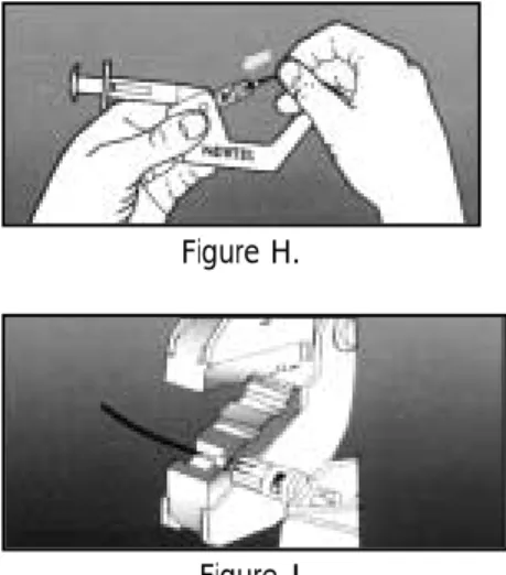
8. Carefully insert the fiber into the stem of the connector body. Gently twisting the fiber may ease insertion. Do not twist or remove the fiber once it is fully inserted, the fiber is fully inserted when the 9mm mark on the buffer is reached at the
end of the connector body, ensure there is a slight bow in the fiber, see figure H.
9. Depress the installation tool plunger. Hook release wire, slowly release the plunge, see figure I.
10. Push and rotate the connector body 1/4 turn counterclockwise in order to unlock the connector from the installation tool. Rest the crimping tool against the connector body to ensure it is aligned properly. Using the first die on the first crimping tool, crimp the stern on the buffer at the “ buffer crimp area”, see figure J.
11.Unclamp the fiber. Align and press the rear housing with boot into the front housing until a click is heard. Remove the connector from the installation tool. The installation is complete
. . . .
OPTICAL FIBER TERMINATION:
...
Figure G. Figure H.
Overview:
• A good installer is efficient, organizing the work to complete first thing first. • A good cable set-up means all materials are placed so the cable can be
handled properly.
• Job site should be secured from any occupants of the building or any non-related personnel.
• Equipment should be in proper place for pulling - jackstand, cable tree, tuggers, etc.
Secure the area for Cable pulls:
• Set - up cones and caution tape across the area • Notify proper personnel that work is beginning
Cable Pull set-up:
• Large cable reels may need the use of a Jackstand • Smaller cable reels may need the use of a cable tree • Others:
• Reel-in-a- box • Easy-box
Pulling horizontal pathways:
Horizontal pathways support many different kinds of information for its users: • Voice communications • Data communications • CATV • Alarms / Security • Audio Conduit Pulls:
Conduit provides a good pathway for the cable. Conduit may be made of: • Electrometallic tubing (EMT)
• Rigid metal
• Rigid Polyvinyl chloride (PVC) • Fiberglass
Note: Conduit made of flexible metallic tubing should not be used unless it is the only practical alterna-tive.
Moving the cable ( fiber) through the conduit from one end to the other requires some type of object to precede the cable through the conduit.
PULLING FIBER OPTICS
Fishtape is a steel wire rigid enough to be pushed all the way through the conduit. It is used to
retrieve the pull string from the far end.
Air-Propelled methods include:
• A vacuum on one end and a foam rat or ball on the other end
• A compressed air bottle used to propel a pull string attached to a foam ball or rat • Other devices either purchased or made up on the job
Conduit installations are designed to be parallel or perpendicular to the external walls of the
building.
• No segment of the conduit must not be more than 100 feet in length. • Allow no more than two 90 degrees bends per 100 feet of the cable pull • Minimize the number of pull points
Factors involving pull in conduits:
• Coefficient of friction ( COF ) • Conduit fill ratio • Number of bends • Conduit material
• Maximum cable tension • Amount and type of lubricant- No Lubricants
OPEN CEILING PULLS:
An open ceiling uses a different pulling method from Conduit pulls. Various ways are used to pass the pull string through the trusses or other structural elements. Cables that run through open ceilings should have a straight and smooth path; this is essential for a good cable pull.
Installing cable supports:
• Beam clamps
• J-hooks Note: Install every 4 to 5 feet
• Support rings
Thread pull-string through every support Attach string to cable (pull)
• Do not exceed maximum pulling strength • Be careful not to snag the cable jacket • Use plenum rated cable in plenum areas
...
PULLING ELECTRONIC CABLES
PULLING VERTICAL PATHWAYS Determine the method of pull:
• From top to bottom • From bottom to top
For Vertical pathways, cabling is more easily pulled from the top down than from the bottom up because gravity helps with the pull. It is the preferred method, if the reels of cable can be moved to the top floor. Sometimes this cannot happen because the reels are too large to fit through closet doors or on a freight elevator. When necessity demands it vertical pathways are pulled from the bottom up. In both cases, special cable-handling devices are required:
• Tugger- If pulling from bottom up
• Cable reel brake- If pulling from top down
For both cases of pulling techniques do not exceed the minimum bend radius of the cable and do not exceed the cables maximum pulling tension.
SECURING VERTICAL CABLES:
• Split mesh grip( Can secure and bear the cable’s weight) • Existing cables or raceways
• Cable ties
Minimum bend radius of Fiber optics:
• Indoor fiber cables ( Simplex, Duplex, Breakout, and Distribution ) • Long term - No load: 10 X cable diameter
• Short term - Load : 15 X cable diameter
• Outdoor / Outside Plant fiber cables ( Loose-tube, Micro-loose) • Long term - No load: 15 X cable diameter
• Short term - Load : 20 X cable diameter
Maximum pulling tension of Fiber Optics:
• Simplex: 77 lbs. • Duplex: 154 lbs.
• Distribution: 90 - 3285 lbs. • Breakout: 600 lbs.
. . . .
PULLING FIBER OPTIC CABLE
Figure A.
Maintain Minimum Bend Radius
Fiber optic cables are more rugged than generally perceived, however care must be taken when pulling fiber.
• Do not exceed its minimum bend radius • Do not exceed its maximum pulling tensions
Fiber optic cables are most appropriately installed in a protective innerduct to provide for addi-tional protection for the cable and as an indicator that fiber is present. This method of installa-tion also tends to reduce the pulling tension required.
Innerduct (see figure B):
• Can be purchased with a pull rope pre - installed inside for attaching the fiber cable to be pulled
• Normally are inside conduit, sleeves, or cable trays • Non-plenum usually orange in color
• Plenum usually white or clear in color
Pulling Optical Fibers:
1. Ensure that only tested and accepted lengths of fiber optic cables are installed
• Manufactures read-out (testing) • Continuity check
• OTDR-Optical Time Domain Reflectometer
2. Install and secure innerduct:
• Verify application (Plenum, Non-Plenum) • 4 one inch innerduct to be placed in a 4
inch Conduit
Innerduct / O.D Conduit / I. D
3. Pulling the Fiber Cable:
• Method 1: Most common is to remove the sheath (approx. 10 -12 inches) take the kevlar strength member through the pulling eye and secure with electrical tape
• Method 2:
Place the fiber optic cable in a multi-weave mesh grip of the appropriate size attach the pulling eye with swivel.
Pulling Eye Pulling Eye Cable Jacket
Cable Jacket
Knot in Strength Member Knot in Strength Member
. . . .
PULLING FIBER OPTIC CABLES:
...
.. .. .. .. .. .. .. .. .. .. .. .. .. .. .. .. .. .. .. .. .. .. .. .. .. .. .. .. .. .. .. .. .. .. .. .. .. .. .. .. .. .. .. .. .. .. .. .. .. .. .. .
INSTALLATION CONSIDERATIONS
Aerial
• Use outdoor loose-tube construction • UV and moisture resistant jacket • Do not allow cable to support itself
ALWAYS lash to a messenger
Direct Burial
• Bury below the frost line • Use armored cable for
rodent protection
• Place in pipe for added protection against rodents and digging
Messenger Wire Messenger Wire Outdoor Outdoor Loose-Tube Cable Loose-Tube Cable Lashing Lashing Wire Wire Inner Jacket Inner Jacket Polyethylene Polyethylene Outer Jacket Outer Jacket Polyethylene Polyethylene Corrugated
Corrugated MultipleMultiple Moisture Moisture Blocking Gel Blocking Gel Thermo-Plastic Thermo-Plastic Tube Tube Aramid Strength Aramid Strength Elements Elements
...
...
NEC ARTICLE 770
Three Fiber Optic Cable Types:
1. Non-Conductive
2. Conductive
3. Composite
Grounding
All noncurrent-carrying conductive members shall be grounded in accordance with Article 250
Non-Conductive Fiber Only 770-5
[770-51 (e), (f)]
Allowed in raceway systems designed for Fiber Optics (Plenum or Riser must be listed as such)
770-52 Can occupy same tray with600 volt circuits or less
NOTE: Allow 50 ft. of cable coming into a building or ridged pipe to terminate or splice on to an NEC Rated cable
.. .. .. .. .. .. .. .. .. .. .. .. .. .. .. .. .. .. .. .. .. .. .. .. .. .. .. .. .. .. .. .. .. .. .. .. .. .. .. .. .. .. .. .. .. .. .. .. .. .. .. .. .. .. .. .. .. .. .. .. .. .. .. .. .. .. .. .. .. .. .. .. .. .. .. .. .. .. .. .. .. .. .. .. .. .
NEC ARTICLE 770
Rating Description Permitted
Substitution
OFNP Nonconductive optical fiber plenum cable None
OFCP Conductive optical fiber plenum cable OFNP
OFNR Nonconductive optical fiber riser cable OFNP
OFCR Conductive optical fiber riser cable OFNP, OFCP, OFNR
OFNG Nonconductive optical fiber general-purpose cable OFNP, OFNR
OFCG Conductive optical fiber general-purpose cable OFNP, OFCP, OFNR, OFCR, OFNG, OFN
OFN Nonconductive optical fiber general-purpose cable OFNP, OFNR
OFC Conductive optical fiber general-purpose cable OFNP, OFCP, OFNR, OFCR, OFNG, OFN
...
...
. . . .
FIBER WAVELENGTH
. . . .
OPTICAL POWER BUDGET
• Published by equipment manufacturer
• Compares transmitter power with receiver sensitivity
Example:
Transmitter output 100µW = –10 dBm (62.5/125 fiber)
Receiver sensitivity 1µW = –30 dBm
Loss budget 100:1 = 20 dB
Allowable system loss = 20 dB
• This difference provides allowable system loss
.. .. .. .. .. .. .. .. .. .. .. .. .. .. .. .. .. .. .. .. .. .. .. .. .. .. .. .. .. .. .. .. .. .. .. .. .. .. .. .. .. .. .. .. .. .. .. .. .. .. .. .. .. .. .. .. .. .. .. .. .. .. .. .. .. .. .. .. .. .. .. .. .. .. .. .. .. .. .. .. .. .. .. .. .. .. .. .. ..
FIBER WAVELENGTH
.. .. .. .. .. .. .. .. .. .. .. .. .. .. .. ....
SYSTEM LOSS EXAMPLE
20 dB Power budget
–3 dB System safety margin 17 dB Available budget
–9 dB Cable loss (3 km @ 3dB/km)
–2 dB Allowance for splice losses (4 @ .5dB) –2 dB Allowance for end connectors
–2 dB Allowance for patch panel 2 dB Excess margin
Testing of any installed cabling system is crucial to ensuring the overall integrity and long-term performance of the cabling network. Documenting the test results
quantifies system quality,and identifies system faults.
1. Pre- Installation Testing:
This test is performed before the installation. •Test the reel of fiber cable
• Verifies if cable has been damaged during shipping • Verifies that there is no factor defects
• Verifies that your test results match manufactures test results.
NOTE: The fiber cable should be ordered so that both ends of the fiber cable are accessible for testing.
Testing can be performed by: • Continuity check
• Optical power meter and light source • OTDR
2. Acceptance Testing: End - to - End Attenuation measurement
This is a measure of the optical power loss between cable termination points. Attenuation,or optical power loss is measured in dB or dBm. This is the primary
performance parameter test in the fiber optic system. The attenuation of installed cable system is measured by the insertion loss method, using an optical source and optical power meter to compare the difference in two optical power levels. First measuring how much light is put into the fiber cable at the near end, and then measuring how much light exits the far end after the cable system is inserted in between.
This is the most important test
• Verifies total attenuation of the link
• Verifies all passive components were installed properly • Minimizes down time
Testing can be performed by:
• Optical power meter and light source • OTDR
3. Preventing Maintenance Testing:
This is a periodical test of a link
• Checks the attenuation number with the original acceptance testing numbers • Performed usually at night or weekends
. . . .
TESTING OPTICAL FIBERS:
PRE-TEST ACTIVITIES: ( POWER METER AND LIGHT SOURCE) 1. Determine the cable type:
• Singlemode • Multi-mode
2. Determine the wavelength to be tested • 850 nm
• 1300 nm - 1310 nm • 1550 nm
3. Testing need to only be single direction.
4. Identify the design link attenuation from the work order, job supervisor or power budget report
5. Clean connectors:
• Clean ferrules with isopropyl alcohol and lint free clothes 6. Clean coupler ( Splice bushing )
• Clean with isopropyl alcohol and small lint free pipe cleaner • Stroke the inside a few times
TEST PROCEDURE: POWER METER AND LIGHT SOURCE: CALIBRATION:
1. Turn both Power meter and light source on ( let light source on 3 minutes before testing the link)
2. Remove dust caps form test leads 3. Clean connectors of the test leads
4. Remove dust caps from the power meter and light source 5. Select unit of measure ( dB or dBm )
6. Select wavelength to be used
7. Remove dust caps from the coupler and clean the coupler 8. Attach leads to power meter and light source.
9. Observe the reading on the power meter. (Either write this number down or zero set the power meter if the power meter has the capability to do this).
10. Disconnect the coupler and place dust caps on 11. Disconnect lead from the light source
TEST PROCEDURE: POWER METER AND LIGHT SOURCE: LINK MEASUREMENT: (SEE FIGURE M)
1. Send technician A to the other end of the link. (Taking power meter with a lead (#1) and coupler, fiber attenuation record, two way radio, supplies for cleaning connector and coupler).
2. Send technician B to the other end of the link. (Taking light source with lead (#2) and coupler, two way radio, and supplies for cleaning connector and coupler).
3. Technician A is responsible for which fibers will be tested first • Example: Blue, Red , Green, etc.
4. Technician A places lead #1 with coupler to the first fiber to be tested (power meter is still on).
5. Technician B places lead #2 with coupler to the first fiber to be tested at the other end of the link.
6. Confirm contact
7. Technician A observes reading on the power meter
• Technician either subtracts the reading from calibration reading or records the number if the power meter was zero set.
8. Technician A marks the reading on a fiber optic link attenuation record. What is a fiber optic link attenuation record ?
This is a document or computer spreadsheet where the link attenuation measurements are recorded.
. . . .
TEST PROCEDURES:
Typical OTDR Display ST SMA Source 850nm 1300nm ON OFF ST SMA STORE RECALL OHM WATT A ZERO dB Power Meter OPTION NEXT SAVE PREVIOUS MODE SINGLE MULTI 850 1300 1550 ON OFF U OTDR Every technician should carry one!
Legend: A. Dead zone
B.Fusion splice or bend
C.Mechanical or mated splice, or connectors D.Break in fiber E.Light scattering LOSS! . . . .
TEST PROCEDURES:
FIGURE MFIBER OPTIC COMMUNICATION
.. .. .. .. .. .. .. .. .. .. .. .. .. .. .. .. .. .. .. .. .. .. .. .. .. .. .. .. .. .. .. .. .. .. .. .. .. .. .. .. .. .. .. .. .. .. .. .. .. .. ..
..
FIBER OPTIC TRANSMISSION
AM Modulation
Video Video TX TX CoaxCoax FiberFiber
Light source intensity varies with electrical input Light source intensity varies with electrical input
Video Video TX TX Coax Coax Fiber Fiber
Frequency of light pulse varies with video signal Frequency of light pulse varies with video signal
FM Modulation
Half-Duplex
Full-Duplex
;; ;; CCTV TX RX CCTV Camera Video Monitor 1-Fiber TX RX...
FIBER OPTIC TRANSMISSION
TRANSMISSION SCHEME
TRANSMISSION SCHEME
Channel #
Channel # ModulationModulation WavelengthWavelength 1 2 3 4 FM FM AM AM FM FM AM AM 850nm 850nm 1300nm 1300nm Signal 1 Signal 2 Signal 2 Signal 1 850 nm Transmitter 850 nm Detector 1300 nm Detector 1300 nm Transmitter
Multiplex up to 32 channels and even higher.
.. .. .. .. .. .. .. .. .. .. .. .. .. .. .. .. .. .. .. .. .. .. .. .. .. .. .. .. .. .. .. .. .. .. .. .. .. .. .. .. .. .. .. .. .. .. .. .. .. .. .. .. .
SAFETY
Wear eye protection when cleaving, terminating and splicing fiber.
Fiber fragments can act as splinters and can be difficult to remove.
NEVER look into the end of a fiber cable when using laser light output. Permanent eye damage can result.
Follow all instructions for proper use of solvents and adhesives used for termination and splicing.