Sharif University of Technology
Scientia IranicaTransactions A: Civil Engineering www.scientiairanica.com
Designing granular layers for railway tracks using ray
optimization algorithm
M. Esmaeili
a, J.A. Zakeri
a, A. Kaveh
b, A. Bakhtiary
cand M. Khayatazad
d a. Center of Excellence for Railway Transportation, Iran University of Science and Technology, Narmak, Tehran, P.O. Box16846-13114, Iran.
b. Centre of Excellence for Fundamental Studies in Structural Engineering, Iran University of Science and Technology, Tehran, P.O. Box 16846-13114, Iran.
c. School of Railway Engineering, Iran University of Science and Technology, Tehran, P.O. Box 16846-13114, Iran. d. School of Civil Engineering, Iran University of Science and Technology, Tehran, P.O. Box 16846-13114, Iran. Received 27 July 2013; received in revised form 2 March 2014; accepted 23 June 2014
KEYWORDS Ray optimization; Design of ballasted railway tracks; Meta-heuristic algorithm; Granular layers; Minimum thickness of ballast layer.
Abstract. In this paper, the recently developed meta-heuristic algorithm, named Ray Optimization (RO), was applied to optimize the thickness of granular layers in railway tracks. RO is a multi-agent algorithm, each agent of which is modeled as a ray of light that moves in the search space in order to nd global or near-global optimum solutions. To utilize RO, considering structural and serviceability constraints, rst, hypothetical values of three thicknesses were assigned to the layers. Then, stresses under the sleeper and on the subgrade layer were compared with the allowable values. The total minimum thickness of the layers was also compared with possible minimum thickness (serviceability constraint) and then minimum thickness values were selected. Optimization results showed that the moment of inertia of the rail had no signicant impact on the minimum total thickness of the ballast and sub-ballast layers. On the other hand, train speed and axle load were the parameters that had a considerable eect on the minimum total thickness of granular layers in the railway track.
© 2015 Sharif University of Technology. All rights reserved.
1. Introduction
Ballast and sub-ballast layers in ballasted railway tracks are layers consisting of aggregate (crushed stone) and granular (gravel and sand) materials, respectively. These materials are used as intermediate layers be-tween sleepers and subgrade materials. For designing granular layers in ballasted railway tracks, some impor-tant points should be considered as follows [1-3]:
1. Structural considerations (i.e. ability of granular layers to transfer loads from sleeper to subgrade);
*. Corresponding author. Tel.: +98 21 77240100; Fax: +98 21 73021556
E-mail addresses: m [email protected] (M. Esmaeili); [email protected] (J.A. Zakeri); [email protected] (A. Kaveh)
2. Operational considerations (i.e. providing proper drainage for the railroad as well as granting longi-tudinal and lateral stability to tracks).
In order to obviate the above-mentioned require-ments, a suitable thickness should be adopted for ballast and sub-ballast layers based on the following four important criteria [1,2,4,5]:
(a) Minimum required thickness of ballast for the possibility of a tamping operation.
(b) Minimum thickness of the sub-ballast layer to play the role of the transition zone between ballast and subgrade layers.
(c) Minimum required thickness of granular layers, including ballast and sub-ballast layers to decrease intensity under sleeper pressure to allowable
sub-grade bearing capacity and to avoid shear failure and excessive subsidence in subgrade.
(d) Providing a suitable thickness of granular materi-als for drainage purposes.
Based on the above criteria, many minimum thicknesses have been introduced by domestic and universal codes and regulations, including Leaet 301 of the Management and Planning Organization of Iran (MPOI) [6], the American Railway Engineering and Maintenance of Way Association, the Manual for Rail-way Engineering (the so-called AREMA Manual) [7] and Standard 719 of the International Union of Rail-ways, entitled \Earthworks and Trackbed Construction for Railway Lines" [8].
For instance, Leaet 301 by MPOI has provided the minimum thickness of a ballast layer under dierent conditions. In the main lines of categories A, B, C and D, the minimum thickness of the ballast layer should not be selected less than 300 mm. In the accessory lines, the minimum thickness of the ballast under sleepers has been considered equal to 250 mm. Moreover, in order to provide the stability of railway lines, the minimum thickness of ballast layers should not exceed 500 mm. According to the leaet's condi-tions, the ballast layer thickness should be high enough to decrease the stress on the surface of the ballast layer to an allowable value for subgrade. Moreover, this leaet recommends using linear analysis, nite element modeling or any other exact method for evaluating stress distribution through the ballast layer. On the other hand, in the mentioned leaet, no criterion is presented for minimum sub-ballast thickness. Among domestic standards, only Leaet 394 of MPOI, entitled \Superstructure Design and Monitoring Instruction of High-speed Railway Tracks" [9], has proposed a value of 300 mm as the minimum thickness of sub-ballast.
The Railway Engineering Manual of American Railway Engineering and Maintenance of Way Associa-tion (AREMA) has presented two minimum thicknesses for ballast and sub-ballast layers. In this manual, by limiting stress on the subgrade layer, a number of computational formulas have been suggested to determine the total thickness of ballast and sub-ballast layers. This regulation has explicitly expressed that the minimum ballast layer thickness should not be less than 300 mm. Accordingly, the thickness of the compacted sub-ballast layer is considered equal to 300 mm. It does, however, emphasize the existence of a 150 mm compacted sub-ballast layer for separation purposes of the ballast and subgrade.
Another guideline that presents a methodology for evaluating the thickness of ballast and sub-ballast layers is the UIC code, 719 R, entitled \Earthworks and Track Bed Construction for Railway Lines" [8].
Based on the mentioned standard, an equation has been established for calculating minimum thicknesses of ballast layers, protective layers (sub-ballast) against frost and layers of lter material.
In this paper, ray optimization was applied to optimize the thickness of granular layers in railway tracks. In order to utilize RO considering structural and serviceability constraints, rst, hypothetical values for three thicknesses were assigned to the layers. Then, the stresses under the sleeper and on the subgrade layer were compared with the allowable values. The total minimum thickness of the layers was then compared with the possible minimum thickness (serviceability constraint) and, nally, minimum thickness values were selected.
2. Reviewing optimization applications in railway engineering
Despite the signicance of optimization in the railway industry, little optimization work has been so far performed. For example, Nielsen [10] optimized the acoustic of a railway sleeper using a mathematical approach. Qiao et al. [11] applied a commercial pro-gram, IDESIGN, to propose optimized wood railroad crossties encased with Glass Fiber-Reinforced Plastic (GFRP). Markine et al. [12] performed multi-criteria optimization on Embedded Rail Structure (ERS) by a numerical technique, using multipoint approximations based on a response surface tting (MARS) method. Sadeghi and Babaee [13] investigated 40 pre-stressed concrete sleepers with dierent dimensions and selected the best one in comparison to the concrete sleeper type B70 commonly used in Iranian railways. As shown, in spite of the importance of determining the optimum thickness of granular materials in conventional railway tracks, no work has been conducted in this regard. So, the present study was devoted to this issue. Details of the research methodology are described in the following section.
3. Research methodology
In this paper, the recently developed optimization algorithm, called Ray Optimization (RO), was used for optimizing the thickness of granular layers in ballasted tracks. The RO algorithm is categorized among multi-agent meta-heuristic methods, which uses the Snell light refraction law for navigating its agents in the search space.
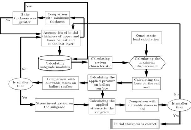
In order to dene optimum thickness, the rst step is to calculate the subgrade modulus using the pyramid method developed by Ahlbeck et al. [14]. This method is capable of estimating the modulus of a railway track considering a series of springs, which correspond to substructure layers. In the next
Figure 1. Flowchart of calculation of ballast layer thickness.
Table 1. Mechanical and geometrical characteristics of components of ballasted railway track. Track
parameters E (pa) I (m4) L (m) B (m) b() sb() Eb(pa) Esb(pa) C0 mN3
Rail 207 109 30:55 10 6 { { { { { { {
Sleeper { { 2.6 0.22 { { { { {
Ballast { { { { 65.2 65.2 250 106 { {
Sub-ballast { { { { 65.2 65.2 { 150 106 {
Subgrade { { { { { { { { 106
step, using the Beam On Elastic Foundation (BOEF) formulation developed by Winkler [15], maximum rail deection was calculated considering the superposition of loads of quasi-static train wheels. Afterward, know-ing the subgrade modulus and maximum rail deection, stress distribution was calculated under the sleepers. In order to determine stress at the subgrade level, Love's equation [1], based on the theory of elasticity, was used. A summary of the owchart of minimum thickness calculation is shown in Figure 1. Details of the calculation methods are described in the next section.
4. Design principles of ballast layer thickness In this section, the calculation process of granular material thickness is presented considering specica-tions of a formal ballasted track. Specicaspecica-tions of each component are presented in subsequent sections. Mechanical and geometrical characteristics of ballasted
railway track components are demonstrated in Ta-ble 1.
To simplify, by applying impact factor () (calcu-lated by Eq. (1)), static load became quasi-static [16].
' = 1 + 5:21V D
Pd= ' P
)
(1) 4.1. Evaluating track modulus using pyramid
model
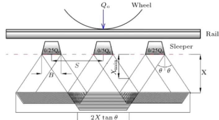
The pyramid approach is an approximate analytical method for evaluating track vertical stiness. The main assumption in the method pertains to pyramidal distribution of stress under the sleeper to subgrade (Figure 2(a)). In this model, each component of the track substructure is replaced with an elastic spring; so, total track stiness is evaluated as the sum of these springs in a series form (Figure 2(a)).
How to calculate the modulus of subgrade using the pyramid method is summarized below.
Figure 2. Track modulus using pyramid model: a) Stress distribution pattern beneath the rail; and b) series springs as representatives of track components.
Table 2. Results of plate load test on the pre-consolidated clay.
Clay quality Hard Very dry Dry quvalues
(kPa) > 428 214-428 107-214 C0 ranges
(10 6kN/mm3) > 68 34-68 17-34
Proposed values of C0
(10 6kN/mm3) 102 51 25.5
Since types of ballast and sub-ballast materials were known, the internal distribution angle was calcu-lated according to Table 1.
If the subgrade layer is made of over-consolidated clay, the reaction modulus could be related to undrained compressive strength, qu. Terzaghi proposed
Table 2 for dierent types of clay [18].
In this study, the reaction modulus of subgrade material was selected based on over-consolidated clays under dry conditions.
4.2. Loading model conguration
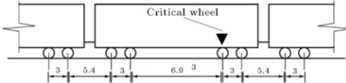
In this section, the car body used for introducing the loading model is presented [17]. As shown in Figure 3, all dimensions of the car body are in meters, while
Figure 3. Body dimensions of the used car.
its wheel diameter is 860 mm. The critical wheel in the gure points to the calculation location of rail deection.
4.3. Calculating under-sleeper pressure and its distribution on subgrade
After calculating maximum rail deformation under the benchmarked wheel location, rail seat load (Qm) was
calculated according to Eqs. (2) and (3), knowing parameter S as the distance between sleepers. Then, using Eq. (4), under-sleeper pressure (Pm) was
ob-tained, where Ab is the eective under-sleeper seating
area, which is equal to B L and 2
3 (B L) for
concrete and wooden sleepers, respectively [1].
To calculate distributed pressure on the subgrade level (PC), Love's Eq. (5) can be utilized:
Fm= U Ymax; (2)
Pm= 2 QA m
b ; (4)
Pc= Pm
2
41 1
1 + r2 h2
!3 23
5 : (5)
In the above equations, r is the radius of a circle with the seating area equivalent sleepers, and h is the thickness of the granular (ballast and sub-ballast) layers.
5. Optimizing granular material thickness using RO algorithm
RO is a multi-agent meta-heuristic algorithm, which was proposed by Kaveh and Khayatazad [18] for nding near-global optimum in optimization problems. Similar to other multi-agent methods, RO has a number of particles consisting of variables of the problem, which are considered rays of light. Based on the Snell light refraction law, when light passes from a lighter medium to a denser one, it refracts and its direction changes. Using this phenomenon, the solution vector can be led to a global or near-global optimum solution. Kaveh and Khayatazad showed the eciency of this algorithm by solving some benchmarks and well-studied engineering problems in 2012 [19] and also used RO for optimizing the size and shape of truss structures [19]. Finally, they optimized cantilever retaining walls under pseudo-dynamic analysis by the RO method [20]. Afterwards, the RO method was utilized for nding the optimum thickness of granular materials in ballasted railway tracks.
5.1. Dening constraints
In order to determine the optimum thickness of granu-lar layers, two separate constraints could be dened as follows:
Serviceability constraint;
Structural constraint.
In order to express the serviceability constraint, Eq. (6) can be used. By limiting compressive stress in separating the boundary between ballast and sub-grade, ballast penetration into the subgrade layer was prevented.
Due to imposing the above-mentioned limitation, the minimum thickness of the ballast layer could be obtained by the following equation:
Zmin=2 tan S B: (6)
In the above equation, S, B and are distance between sleepers, width of sleepers and angle of internal stress distribution through the ballast layer, respectively.
Figure 4. Minimum thickness of granular materials.
Figure 4 graphically illustrates the philosophy of min-imum thickness based on the above criteria [2].
In order to dene the structural constraint, the value of the applied pressure beneath the concrete sleeper on the ballast surface had to be limited to 590 kPa, according to the AREMA manual [1]. From another point of view, the transferred pressure to the subgrade through the ballast layer had to be limited to the allowable bearing capacity of the subgrade. For over-consolidated clay in a dry condition, the allowable bearing capacity of subgrade (qc) could be evaluated
by the following equation [21]:
qc= 40 F.S. C0; (7)
where F.S. is the factor of safety equal to 1.5, and C0
is the reaction modulus of the subgrade.
5.2. Dening optimization variables and goal function
The vector of optimization variables can be introduced as follows:
X = (x1; x2; x3): (8)
In this vector, x1, x2 and x3 are thicknesses of upper
ballast, lower ballast and sub-ballast layers, respec-tively. In each new step of the calculation, based on the introduced algorithm, all vector components were assumed to have thicknesses in the range of 0 to 500 mm. Consequently, according to Figure 1, the modied thicknesses were evaluated.
The selected goal function of the problem was minimized by the following equation:
H = x1+ x2+ x3;
where H is minimum total thickness of granular mate-rials in the ballasted track.
5.3. Concepts of RO optimization algorithm Consider a light ray which is crossing transparent medium K with Vk
i (Figure 5). When this ray reaches
Xk
i, after refraction, it enters a darker medium, K + 1,
and continues its path with Vk+1
Figure 5. Incident and refracted rays and their specications.
Vk+1
i depends on the direction of n and the refraction
index ratio, (nd nt).
RO method is a multi-agent optimization method which is inspired by the light refraction concept [18]. In this method, by moving the agents to new positions, an optimal solution is found. Thus, if the movement vector for the ith agent in the kth iteration is Vk
i and
the current position of this agent is Xk
i, it can be moved
to its new position by Vk+1
i . The refraction index ratio
for this method is selected as 0.45. The direction of n passes through two points: the beginning point of Ok i
and the nal one of Xk
i. Oki is dened as follows:
OK
i = (ite + k):GB + (ite k):LB2:ite i; (9)
where GB and LBi are the so-far best position and
goal function values obtained by all the agents and the ith agent, respectively.
If the number of variables is greater than 3 (N > 3), for using the ray tracing concept, the search space can be divided to a number of 2D and or 3D spaces. In general, if N is an even number, the search space is divided into N
2 for 2D spaces; if N is an odd number,
the search space is divided into N 3
2 for 2D space(s)
and a one 3D space. Each of these 2D or 3D spaces is named a sub-space. With this description, Vk
i;l is the
movement vector of the lth sub-space which belongs to the ith agent in the kth iteration, and vk
i;j;l is the jth
component of movement vector of the lth sub-space, which belongs to the ith agent in the kth iteration.
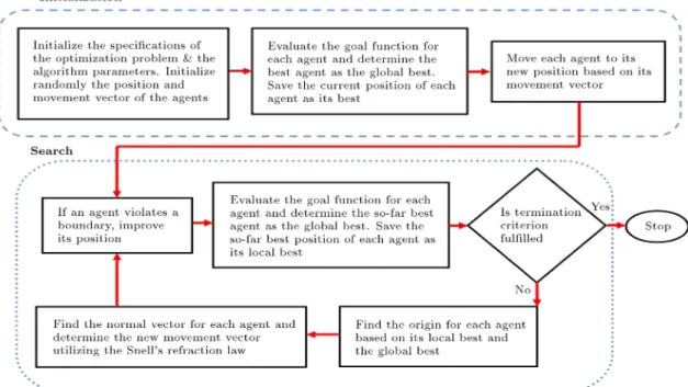
The steps of the RO algorithm are described below and its owchart is shown in Figure 6.
The steps of the calculations based on the RO algorithm are as introduced below.
5.3.1. Scattering and evaluation steps
Based on Eq. (10), randomly scatter the agents in the search space:
x0
i;j= xj;min+ rand (xj;max xj;min); (10)
where x0
i;jis the jth component of the ith agent. xj;min
and xj;max are allowable minimum and maximum
values of the jth component. rand is a random number distributed 0 through 1. After scattering, evaluate the value of the goal function for each agent. Then, save the position and goal function values of each agent and the best position and goal function values of the best agent, as LBi and GB, respectively.
Make a movement vector for each agent as follows:
v0
i;j= 1 + 2 rand; (11)
where v0
i;j is the jth component of the ith agent.
Finally, based on the sub-space grouping, convert 2D and 3D movement vectors into normalized ones. 5.3.2. Movement vector and motion renement steps Move the agents to their new positions based on their movement vectors. If an agent violates the allowable boundaries, modify the length of its movement vector. The new length of the movement vector equals 0.9 times the distance of the current agent position and the intersection of the boundary. After modifying the movement vector, evaluate the goal function of each agent and update GB and LBi.
5.3.3. Cockshy point making and convergent step Determine Ok
i for each agent. Then, based on Eq. (12),
obtain the new movement vector, where stoch and d are 0.35 and 7.5, respectively.
Xk
i;l6= Oki;l!
8 > > > > > > > > > > > > > > > > > > > > > > > > > < > > > > > > > > > > > > > > > > > > > > > > > > > :
w.p.(1 stoch) ! Vk+1
i;l = V(k+1)i;l
norm(Xk
i;l Oki;l)
V(k+1)i;l is determined by ray tracing:
w.p. stoch ! Vi;l(k+1)= V(k+1)i;l norm(V(k+1)i;l )
a
d rand
Each component of Vi;l(k+1) is calculated as blow: vi;j;l(k+1)= 1 + 2 rand a =qPnj=1(xj;max xj;min)2
n = (
2 for two variable groups 3 for three variable groups
(12)
Xk
i;l= Oki;l! V(k+1)i;l =
Vk i;l
norm(Vk
i;l) rand 0:001:
5.3.4. Finish or redoing step
If the nishing criterion of the algorithm is obtained, the search procedure is terminated; otherwise, the algorithm returns to the second step and continues the searching. The nishing criterion can be a specic number of iterations for obtaining the optimal solu-tion.
6. Numerical results and discussion
In this section, the results extracted from the opti-mization algorithm are presented in the framework of some numeric examples. To demonstrate the practical application of the described algorithm, the inuence of parameters such as rail type, train axle load, wheel di-ameter of train, width of sleeper and distance between
sleepers on the minimum total thickness of ballast and sub-ballast layers is investigated. In all the graphs, axle load was considered constant and other parameters were changed (except for Figure 10).
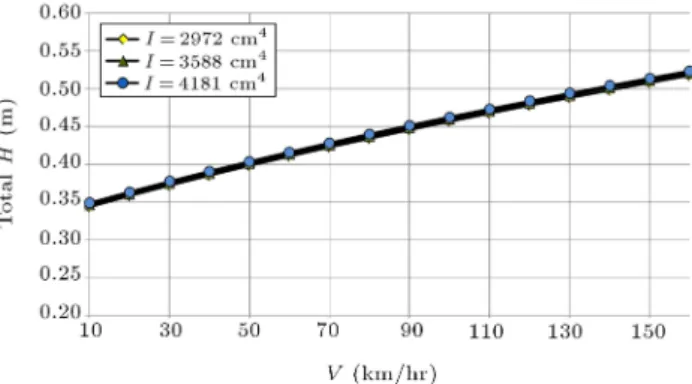
6.1. Eect of rail type on total thickness As seen in Figures 7-9, with increasing train speed from 10 to 160 km/hr, minimum total thickness of the ballast and sub-ballast layers increased. Each of these graphs is plotted for dierent moments of inertia of the rail. For this purpose, four rail proles (119 RE, 133 RE and 141 RE) were selected, according to AREMA regulations.
As shown, an increase in the moment of inertia
Figure 7. Variation of total thickness of granular materials versus train speed for 8 ton axle load.
Figure 8. Variation of total thickness of granular materials versus train speed for 9 ton axle load.
Figure 9. Variation of total thickness of granular materials versus train speed for 10 ton axle load.
Figure 10. Minimum total thickness of granular materials versus train speed for dierent axle loads.
of the rail, in the case of train axle loads of 8, 9 and 10 tons, caused a reduction in the minimum total thickness of granular materials by about 1.6%, 1.5% and 1.4%, respectively. Overall, an increase in moment of inertia of the rail from 2972 cm4to 4181 cm4did not
considerably aect the reduction of the total thickness of granular materials.
6.2. Eect of axle load on total thickness of granular materials
The minimum total thickness of granular materials is presented for dierent train speeds in Figure 10. In this diagram, it is evident that, due to an increase in train speed, minimum total thickness increased. Moreover, with increasing axle load, the minimum total thickness of granular materials was raised.
With increasing train speed from 10 to 160 km/hr, all the diagrams showed a smooth growth with a linear pattern.
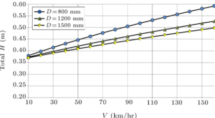
6.3. Eect of train wheel diameter on minimum total thickness of granular materials
As illustrated in Figures 11 to 13, due to the eect of wheel diameter on increasing the impact factor of the axle load, an increasing trend was observed in the minimum total thickness of granular materials.
In these gures, with increasing train speed, minimum total thickness was increased. However,
de-Figure 11. Minimum total thickness of granular materials versus train speed for 8 ton axle load.
Figure 12. Minimum total thickness of ballast layer versus train speed for 9 ton axle load.
Figure 13. Minimum total thickness of granular materials versus train speed for 10 ton axle load.
creasing wheel diameter caused an increased minimum total thickness of granular materials for three dierent values of axle load, i.e. 8, 9 and 10 tons.
This increase was more evident at a speed of 160 km/hr, so that, in axle loads of 8 tons, 9 tons and 10 tons, decreasing wheel diameter from 1200 to 800, in comparison to 1500 to 1200, caused a 212%, 214% and 215% increase in minimum total thickness of granular materials, respectively.
6.4. Eect of width of sleeper on minimum total thickness of granular materials In Figures 14-16, variations of minimum total thickness are illustrated for three dierent sleeper widths (0.15 m, 0.22 m and 0.3 m). Due to an increase in the
Figure 14. Minimum total thickness of granular materials versus train speed for 8 ton axle load.
Figure 15. Minimum total thickness of granular materials versus train speed for 9 ton axle load.
Figure 16. Minimum total thickness of granular materials versus train speed for 10 ton axle load.
Figure 17. Minimum total thickness of granular materials versus train speed for 8 ton axle load.
running speed of the train, the calculated minimum total thickness decreased with increasing the sleeper width.
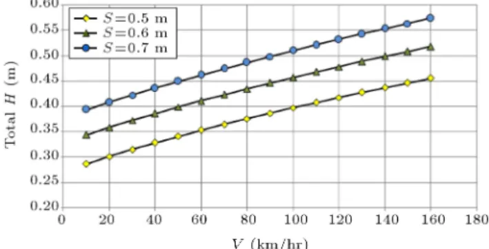
6.5. Eect of sleeper distance on total thickness
In Figures 17-19, a minimum total thickness variation is shown for three dierent distances of sleepers (0.5 m, 0.6 m and 0.7 m).
The presented gures evidently prove the increas-ing trend of the minimum total thickness of granular materials due to the increase in sleeper distance for the whole range of train speed.
Figure 18. Minimum total thickness of granular materials versus train speed for 9 ton axle load.
Figure 19. Minimum total thickness of granular materials versus train speed for 10 ton axle load.
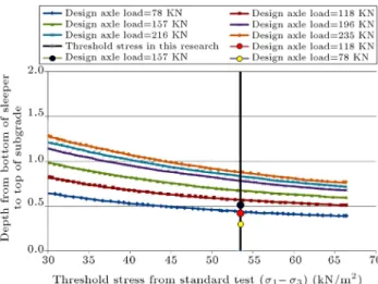
7. Validation of the proposed method to determine the optimum thickness of granular material
In order to validate the optimization method used in the present research for evaluating the thickness of granular material in ballasted tracks, a comparison is made with the proposed method of British Railway. This method is usually used for determining the whole thickness of the ballast and sub-ballast layer as a granular layer. The base of the mentioned method has been established by British Railway and the Oce for Research and Experiments of the International Union of Railways (UIC) in parallel with extensive eld and laboratory experiments. The main inputs of the method are: Threshold stress of subgrade material and design axle load, which is the real axle load multiplied to impact factor. In this section, recalling the used input data in the previous sections, the comparison is fullled with the optimized values of granular material thickness proposed in this research.
By assuming the value of the threshold stress for over-consolidated clay in dry condition (the subgrade material) as 53.5 kPa, and adopting the design axle load as static axle load multiplied to the impact factor of Eq. (1), selecting the wheel diameter as shown in Figure 3 and train speed as in Figure 10, three dierent thicknesses are obtained with respect to design axle loads 78, 118 and 1157 kN, as illustrated in Figure 20.
Figure 20. Total thickness of granular materials versus threshold stress from British Railway method.
As seen in these points, for the design axle load equal to 78 kN, the calculated optimized thickness is less than the recommended amount by British Railway (about 14.4 cm) [1]. For the design axle load equal to 118 kN and 157 kN, the calculated optimized thickness has fallen about 15.1 cm and 16.7 cm, respectively. These results prove the eciency of the proposed optimization process in the present study in determining the whole thickness of granular material in ballasted tracks. 8. Conclusions
In this paper, a ray optimization algorithm was used for nding the optimal thickness of granular materials in traditional ballasted railway tracks. In this regard, a step-by-step calculation process was introduced and two dierent structural and serviceability constraints were imposed. Consequently, by limiting the under-sleeper pressure and distributed stress on the subgrade to the allowable values, the optimum thickness of gran-ular layers, including ballast and sub-ballast layers, was evaluated. As part of the study, sensitivity analyses were performed to evaluate the eect of train speed and axle load, wheel diameter, sleeper width and sleeper distance on the total optimized thickness of granular materials. The main ndings of this research can be summarized as follows:
1. An increase in the moment of inertia of the rail from 2972 cm4 to 4181 cm4 did not have a considerable
eect on reducing the total thickness of granular materials. Thus, with increasing the moment of inertia of the rail from 2972 cm4to 4181 cm4,
max-imum and minmax-imum thickness ratios of granular materials were related to the speed of 10 km/hr with a value of 1.016, and the speed of 160 km/hr with a value of 1.012. Also, with increasing the moment of inertia of the rail from 2972 cm4 to
3588 cm4, maximum and minimum thickness ratios
of granular materials were related to the speed of 10 km/hr with a value of 1.009, and the speed of 160 km/hr with a value of 1.007.
2. With increasing the train speed from 10 to 160 km/hr and at various axle loads, smooth growth with a linear pattern occurred in the total thickness of granular materials. Thus, the thickness ratio of granular materials at a load equivalent to 10 tons to another equivalent to 8 tons at a speed of 10 km/hr was reduced from 1.22 to 1.16 at the speed of 160 km/hr, indicating the reduced eect of axle load on granular material thickness.
3. Increasing impact factor from 1.043 (equivalent speed of 10 km/hr and wheel diameter of 1200 mm) to 1.695 (equivalent speed of 160 km/hr and wheel diameter of 1200 mm) caused an increase in the minimum total thickness of granular materials from 31 cm to 45 cm, showing that the minimum thick-ness of granular materials decreased with increasing the impact factor at constant axle load.
4. In an 8 tons equivalent axle load, the minimum total thickness of granular materials in 22 cm width concrete sleepers increased from 31 cm to 48 cm at speeds of 10 km/hr and 160 km/hr, respectively. However, in the same axle load and 30 cm width concrete sleepers, these thicknesses were 26 cm and 44 cm at speeds of 10 km/hr and 160 km/hr, respectively, representing a decrease of 19% and 9% in the minimum total thickness of granular materials.
5. With increasing sleeper distance from each other, the minimum thickness of granular materials was increased. As an example, in an 8 ton axle load, with increasing distance between the sleepers from 50 cm to 70 cm, the highest and lowest increases in thickness were related to the speeds of 10 km/hr and 160 km/hr, with values of 47% and 27%, respectively.
References
1. Selig, E.T. and Waters, J.M. \Track geotechnology and substructure management", In Railway Engineering and Its application, Thomas Telford Press. UK, pp. 8.5-8.18 (1994).
2. Lichtberger, B. \Track compendium, formation, per-manent way, maintenance and economics", In Railway Engineering, Eurail Press, Hamburg, Germany (2005).
3. European Committee for Standardization, EN 13450, \Aggregates for railway ballast" (2002).
4. Esveld, C., Modern Railway Track, 2nd edn. In Rail-way Engineering TU-Delft Press, pp. 428-430, Delft, the Netherlands (2001).
5. Kerr, A.D., Fundamentals of Railway Track Engineer-ing, Simmons-Boardman Books, Inc (2003).
6. Leaet 301 of Iran, No. 1, General and Technical Specications of Railway Superstructure, No. 1, pp. 80-83 (2005).
7. American Railway Engineering and Maintenance of Way Association, Roadway and Ballast, Manual for Railway Engineering, Volume 1, Chapter 1 (2006).
8. International Union of Railways, Earthworks and Track Bed Construction for Railway Lines, UIC CODE, 719 R, 2nd Edition (1994).
9. Leaet 394 of Iran, No. 1, Guideline of Design and Monitoring of Superstructure of High Speed Railway, No. 1, pp. 80-83 (2007).
10. Nielsen, J.C.O. \Acoustic optimization of railway sleepers", Journal of Sound and Vibration, 231(3), pp. 753-764 (2000).
11. Davalos, J.F. and Zipfe, M.G. \Modeling and optimal design of composite-reinforced wood railroad crosstie", Journal of Composite Structures, pp. 87-96 (1998).
12. Man, A.P. de, Jovanovic, S. and Esveld, C. \Multi criteria optimization of railway track for high-speed lines", Section of Road and Railway Engineering Fac-ulty of Civil Engineering, Delft University of Technol-ogy Stevinweg 1, NL-2628, CN Delft, the Netherlands (2000).
13. Zakeri, J.A. and Bakhtiary, A. \Comparing lateral resistance to dierent types of sleeper in ballasted rail-way tracks", International Journal of Scientia Iranica, 21(1), pp. 101-107 (2014).
14. Meacham, H.C. and Prause, R.H. \The development of analytical models for railroad track dynamics", in A.D. Kerr (Ed.), Railroad Track Mechanics & Technology, Pergamon Press, Oxford (1978).
15. Tsudik, E., Analysis of Beams and Frames on Elastic Foundation, Traord Publishing (2006).
16. Zhai, W.M., Wang, K.Y. and Lin, J.H. \Modelling and experiment of railway ballast vibrations", Journal of Sound and Vibration, 270, pp. 673-683 (2004).
17. Cheng, Y.C. \Modeling and nonlinear hunting stabil-ity analysis of high-speed railway vehicle moving on curved tracks", Journal of Sound and Vibration, 324, pp. 139-160 (2009).
18. Kaveh, A. and Khayatazad, M. \A new meta-heuristic: Ray optimization", Computers and Structures, 112-113, pp. 283-294 (2012).
19. Kaveh, A. and Khayatazad, M. \Ray optimization for size and shape optimization of truss structures", Computers and Structures, 117, pp. 82-94 (2013).
20. Kaveh, A. and Khayatazad, M. \Optimal design of cantilever retaining walls using ray optimization method", Submitted for publication (2013).
21. Bowles, J.E., Foundation Analysis and Design, 5th Ed. McGraw-Hill, New York (1997).
Biographies
Morteza Esmaeili obtained his BS degree from the Department of Civil Engineering at Iran Uni-versity of Science and Technology (IUST), Tehran, Iran, and MS and PhD degrees in Geotechnical En-gineering from the University of Tehran (UT), Iran. He is currently Associate Professor at the School of Railway Engineering at Iran University of Science and Technology (IUST). His key research interests and areas of expertise include track geo-technology, mechanics of porous media, train induced vibra-tion and design of ballast-less tracks. He has also published ve books in dierent elds consisting of bridge substructure design, TBM tunneling, railway track geo-technique, soil steel bridges and ballast-less tracks.
Jabbar Ali Zakeri received his BS degree in Civil Engineering and MS degree in Structural Engineering from the University of Tabriz, Iran, in 1992 and 1995, respectively. He also received his PhD degree in Road and Railway Engineering from Beijing Jiaotong Univer-sity, China, in 2000. Dr Zakeri is currently Associate Professor at the School of Railway Engineering, Iran University of Science and Technology. His research interests include dynamic analysis of train-track inter-action, railway track dynamics, track maintenance and construction.
Ali Kaveh was born in 1948 in Tabriz, Iran. He obtained his BS degree from the Department of Civil Engineering, University of Tabriz, Iran, in 1969, and MS and PhD DIC degrees (Structures) from Impe-rial College of Science and Technology, University of London, UK, in 1970 and 1974, respectively. He is presently Professor of Structural Engineering at Iran University of Science and Technology, Tehran, Iran. Professor Kaveh has authored many papers published in international journals and presented at international conferences. He has 23 books published in Farsi and 4 in English, published by Wiley, Springer, the American Mechanical Society and Research Studies Press.
Arash Bakhtiary received his BS degree in Civil En-gineering from Bu Ali Sina University, Hamedan, Iran, in 2010, and MS degree in Railway Engineering from Iran University of Science and Technology (IUST), Tehran, Iran, in 2013. He was ranked rst student in education in 2013, and once for research at IUST. His research interests include numerical analysis of railway tracks, new tools for prediction and optimization
meth-ods, such as neural networks, meta-heuristic algorithms and Design Of Experiments (DOE).
Mojtaba Khayatazad was born in 1987, in Mashhad, Iran. He obtained his BS degree in Civil Engineering
from Ferdowsi University of Mashhad (FUM), Iran, and his MS degree from Iran University of Science and Technology, Iran, in 2012. He is currently a PhD degree candidate at FUM. His research interest include optimum design of dierent structures.