Sharif University of Technology
Scientia IranicaTransactions A: Civil Engineering www.scientiairanica.com
A three-dimensional peano series solution for the
vibration of functionally graded piezoelectric laminates
in cylindrical bending
M. Lezgy-Nazargah
Faculty of Civil Engineering, Hakim Sabzevari University, Sabzevar, P.O. Box 9617976487, Iran. Received 21 August 2014; received in revised form 30 June 2015; accepted 7 October 2015
KEYWORDS Vibration analysis; Peano series solution; State-space approach; Functionally
graded piezoelectric materials.
Abstract. The available three-dimensional (3D) solutions reported for the analysis of Functionally Graded Piezoelectric (FGP) laminates are based on this simplifying assumption that the FGP layer consists of a number of homogeneous sub-layers. The accuracy of these formulations not only is dependent on the number of sub-layers, but also leads to inaccurate results in the prediction of higher natural frequencies of the FGP laminates. In the present paper, a 3D Peano series solution is developed for the cylindrical bending vibration of the FGP laminates. This novel formulation exactly satises the equations of motion, the charge equation, and the boundary and interface conditions of the continuously nonhomogeneous piezoelectric layers. The obtained solution is exact because no a priori assumption for the displacement components and the electric potential along the thickness direction of FGP layers is introduced. The inuences of the dierent functionally gradient material properties and dierent electric boundary conditions on the natural frequencies and mode shapes of the FGP laminate have also been studied through examples. The present solution and its obtained numerical results can be employed to assess the accuracy of dierent FGP laminated beam/plate theories. It can also be used for FGP vibration behavior comprehension purposes.
© 2016 Sharif University of Technology. All rights reserved.
1. Introduction
Behaviors of the laminated piezoelectric structures have been of intense research interests for more than two decades [1]. Various studies are available in the open literature which deal with the prediction of static and dynamic behaviors of piezoelectric lami-nated composite structures as well as their eective electromechanical properties [1-13]. The conventional piezoelectric devices are made of several layers of dier-ent piezoelectric materials. Although this convdier-entional type of design may provide larger deformations, it
*. Tel.: +98 5744012784; Fax: +98 5744012771 E-mail addresses: [email protected] and [email protected]
has several restricting disadvantages that reduce its reliability. For the piezoelectric actuators made of dierent piezoelectric layers or identical piezoelectric layers with dierent poling directions, high stress concentrations usually appear in the layer interfaces under mechanical or electrical loading [14]. These stress concentrations lead to the initiation and prop-agation of micro-cracks near the interfaces of two bonded piezoelectric layers [15]. The lifetime and the reliability of these structures signicantly reduce with the aforementioned drawbacks. In order to overcome the performance limitations of the traditional layered piezoelectric elements, the concept of functionally graded piezoelectric sensors and actuators emerged [16-17]. Functionally graded piezoelectrics are microscop-ically heterogeneous materials attributed by a smooth
and continuous variation in mechanical and electrical properties along any/all directions in the reference coordinate system. Functionally graded piezoelectric actuators can not only produce large displacements but also reduce the internal stress concentrations and consequently improve the lifetime of piezoelectric actu-ators, signicantly [14]. It is obvious that functionally graded sensors and actuators will have a signicant function in the eld of smart materials and structures. Research on static and/or dynamic behavior of FGP structures has been carried out by many researchers and various mathematical models have been developed until now. These mathematical models can be classied into two broad categories including two-dimensional (2D) models and three-dimensional (3D) models. In the following two paragraphs, these groups have been adequately reviewed.
In 2D models, the variations of the displacement components and the electric potential in the transverse direction of FGP structures are prescribed [7]. This idea is the origin of all of the beam/plate/shell theories presented for the analysis of these types of struc-tures. Yang and Xiang [18] investigated the static and dynamic responses of FGP actuators under thermo-electro-mechanical loadings by using the Timoshenko beam theory. In their work, the numerical results were obtained by using the Dierential Quadrature Method (DQM). A comprehensive study on the static, dynamic, and free vibration responses of FGP panels under dif-ferent sets of mechanical, thermal, and electrical load-ings using the nite element method was presented by Behjat et al. [19]. They obtained the governing equa-tions using potential energy and Hamilton's principle based on the rst-order shear deformation theory that includes thermo-piezoelectric eects. Behjat et al. [20] also investigated the static bending, free vibration, and dynamic response of FGP plates under mechanical and electrical loads using the rst-order shear deformation theory. Wu et al. [21] derived a high-order theory for FGP shells based on the generalized Hamilton's principle. Doroushi et al. [13] studied the free and forced vibration characteristics of an FGP beam under thermo-electro-mechanical loads using the higher-order shear deformation theory. Lezgy-Nazargah et al. [15] proposed an ecient nite element model for static and dynamic analyses of FGP beams. They used an ecient three-nodded beam element which was based on a rened sinus model. The proposed beam element of these researchers does not require shear correction factor and ensures continuity conditions for displacements and transverse shear stresses as well as boundary conditions on the upper and lower surfaces of the FGP beam. Lee [22] used a layerwise nite element formulation to investigate the displacement and stress response of an FGP bimorph actuator. By using the rened 2D models, Brischetto and Carrera [23]
studied the static response of a single layered FGP plate. In this work, Carrera's unied formulation has been extended to FGP plates in the framework of the principle of virtual displacements.
In 3D models, the governing dierential equations of the 3D theory of piezoelasticity are solved using dierent analytical methods [7]. In these models, no a priori assumption for the displacement components and the electric potential along the thickness direction of FGP layers is introduced. To assess the validity of approximate theories related to FGP structures, obtaining analytical solutions based on the 3D theory of piezoelasticity is necessary [24]. By dividing the FGP layer into a number of homogeneous sub-layers, Reddy and Cheng [25] obtained a 3D solution for smart functionally gradient plates. Liu and Tani [26] used this sub-layer structure scheme to study the wave
propagation in FGP plates. Chen and Ding [27]
analyzed the free vibration of FGP rectangular plates using the aforementioned method. Based on the 3D theory of piezoelectricity, the method called state-space based DQM was employed by Li and Shi [28] to study the free vibration of an FGP beam under dierent boundary conditions. In this work, the FGP beam is also approximated as a multi layered cantilever. Zhong and Shang [29] presented an exact 3D solution for bending analysis of rectangular piezoelectric plates with exponent-law dependency of electromechanical properties on the thickness-coordinate by means of the state-space approach. Lu et al. [24] presented an exact solution for simply supported exponentially non-homogeneous piezoelectric laminates in cylindrical bending by Stroh-like formalism. Using this method, Lu et al. [30] also proposed the exact solutions for bending analysis of simply supported FGP plates. Liu and Shi [31] and Shi and Chen [32] obtained closed form solutions for the FGP cantilever beams using the 2D theory of piezoelasticity and the Airy stress function. Xiang and Shi [33] investigated thermo-electro-elastic response of an FGP sandwich cantilever. They also employed the Airy stress function in or-der to study the eect of parameters such as the electromechanical coupling, functionally graded index, temperature change, and thickness ratio on the static behavior of actuators/sensors. Lim and He [34] ob-tained an exact solution for a compositionally graded piezoelectric layer under uniform stretch, bending, and twisting. Lezgy-Nazargah [35] introduced a three-dimensional exact state-space solution for cylindrical bending of continuously non-homogenous piezoelectric laminated plates with arbitrary gradient composi-tion.
The exact 3D formulations available in the lit-erature mostly consider the static bending of FGP structures. The rare exact 3D solutions can be found in the literature for the accurate dynamic analysis of
FGP laminates. The available limited studies [25-28] which consider dynamic problems of FGP devices are based on this unjust assumption that the FGP layer consists of a number of homogeneous sub-layers. The preparation of input material data in these methods not only is very time consuming but also their solution accuracy depends strongly on the number of sub-layers. To ll in this gap in the literature, an exact 3D Peano series solution is derived in this study for the cylindrical bending vibration of FGP laminates based on the state-space approach. The obtained solution is exact in that the electric potential, displacements, and stresses exactly satisfy the governing motion equations of anisotropic piezoelasticity, the traction boundary conditions on the top and bottom planes, the end conditions, and the interlaminar continuity conditions
on the interfaces between the layers. Unlike the
sub-layer based methods [25-28], the present study considers FGP layers as the transversely nonhomoge-neous piezoelectric material with continuous variation of electro-mechanical properties along the thickness direction. In deriving the present exact formulation, it is also assumed that all material properties are variable along the thickness direction of the laminates. In order to ensure that there is no algebraic errors in the implementation of the present state-space formu-lation, comparisons have been made with the results obtained from 2D nite element analysis (ABAQUS). The present obtained exact solution could serve as a basis for establishing simplied FGP beam/plate theories.
2. Formulation of the problem
The considered laminate is a prismatic one with a rectangular uniform cross section of length L, height h, and made of Nl layers either completely or in part
from FGP materials. The laminate is assumed to be innitely long in the x2-direction with perfect bonding
between layers. The geometric parameters of the
laminated plate and the chosen Cartesian coordinate system (x2; x2; x3) are shown in Figure 1.
The equations of motion in the absence of body
Figure 1. Functionally graded piezoelectric plate; Cartesian coordinate system and geometric parameters.
forces and free charges for the kth lamina made of a piezoelectric material are:
ij;j(k) = (k)u(k)
i ; D(k)i;i = 0; (1)
where ij, ui, and Di denote the stress tensor, the
displacement vector, and the electric displacement vector components, respectively. is the mass density, and a superimposed dot indicates dierentiation with respect to time t.
In this study, the general type of piezoelectric materials is assumed to be \monoclinic class 2". The 3D linear constitutive equations of the kth layer, polarized along its thickness direction in its global material coordinate system, can be expressed as:
(k)
D(k)
=
c(k) e(k)
e(e) (k) " (k)
E(k)
; (2)
where (k) = f(k)
11 (k)22 (k)33 23(k) 13(k) (k)12gT
is the elastic stress vector, "(k) = f"(k)
11 "(k)22 "(k)33
(k)23 13(k) 12(k)gT the elastic strain vector, E(k) =
fE1(k)E2(k) E(k)3 gT the electric eld vector, and D(k)=
fD(k)1 D(k)2 D3(k)gT the electric displacement vector.
The matrices c(k), e(k), and (k) contain the elastic,
piezoelectric, and dielectric coecients, respectively. Unlike the homogeneous piezoelectric materials, cml,
eim, and ij are now functions of the coordinate
x3. They may vary according to the power law,
exponent-law, or every other arbitrary distribution along the thickness direction of FGP layers. Indeed, the anisotropy of the considered laminated FGP medium of the present study belongs to the monoclinic class 2 with the symmetry axis 2 orthogonal to the layers.
The displacement components are related to the strain components through the relations:
"(k)ij =12u(k)i;j + u(k)j;i: (3) The electric eld components can be related to the electrostatic potential ' using the relation:
Ei(k)= '(k);i : (4)
In cylindrical bending, the laminate is simply sup-ported and the vertical edges are assumed to be grounded.
These conditions can be expressed as: 11(k)(0; x3) = (k)11(L; x3) = 0;
12(k)(0; x3) = (k)12(L; x3) = 0; (5)
u(k)3 (0; x3) = u(k)3 (L; x3) = 0;
'(k)(0; x
Although the electric potential does not vanish at the boundaries, exact 3D solutions for laminated plates can be obtained only for certain combinations of boundary conditions on the edges. In other words, we are able to obtain exact solutions only when the vertical edges of the laminated plate are assumed to be electrically grounded. Heyliger and Brooks [36] have also employed the same assumption in order to obtain the natural frequencies of laminated homogeneous piezoelectric plates in cylindrical bending. All Eqs. (1-6) must be satised for the material properties of a specic layer. In addition to these equations, the following mechanical and electrical boundary conditions on the upper and lower planes must be satised:
33(x1; h) = qt0ei!tsin px1;
33(x1; 0) = qb0ei!tsin px1;
13(x1; h) = 0; 13(x1; 0) = 0;
23(x1; h) = 0; 23(x1; 0) = 0;
'(x1; h) = 't0ei!tsin px1 or D3(x1; h) = 0;
'(x1; 0) = 'b0ei!tsin px1 or D3(x1; 0) = 0; (7)
where qt
0, q0b, 't0, and 'b0 are known constants; p =
n=L, and n is a positive integer; i =p 1; and ! and t denote the angular frequency and time, respectively. It is worth to note that any arbitrary applied traction load or prescribed electric potential on the surfaces of the FGP laminates can be expanded in terms of a sinusoidal (Fourier) series. Also, the following interlaminar continuity conditions on the interfaces between the layers must be ensured:
3i(k)(x1; zk+1) = 3i(k+1)(x1; zk+1);
u(k)i (x1; zk+1) = u(k+1)i (x1; zk+1);
'(k)(x
1; zk+1) = '(k)(x1; zk+1);
D3(k)(x1; zk+1) = D(k+1)3 (x1; zk+1): (8)
3. Exact solution
A solution in the following form is sought for the displacement components and the electric potential of the kth lamina:
u(k)1 (x1; x3; t) = U(k)(x3)ei!tcos px1;
u(k)2 (x1; x3; t) = V(k)(x3)ei!tcos px1;
u(k)3 (x1; x3; t) = W(k)(x3)ei!tsin px1;
'(k)(x
1; x3; t) = (k)(x3)ei!tsin px1: (9)
The above assumed solution is reasonable because the laminates are of innite extent in the x2-direction
and the applied loads and material properties are independent of x2. Indeed, the laminates are in a
generalized plane state of deformation. Moreover, it can be observed that Eq. (9) identically satisfy the boundary conditions (5)-(6) on the edges x1 = 0 and
x1 = L. It is worth to note that no assumption
for U(k)(x
3), V(k)(x3), W(k)(x3), and (k)(x3) is
introduced in Eq. (9). They are unknown functions that must be determined. Substitution of Eq. (9) into Eqs. (3)-(4) and the result into Eq. (2) gives the stresses and electric displacements with respect to the independent unknown eld variables U(k)(x
3),
V(k)(x
3), W(k)(x3), and (k)(x3). By substitution of
these rewritten stress and electric displacement compo-nents into the governing equilibrium equation (Eq. (1)), and expressing the resulting system of second-order dierential equations as a set of rst-order dierential equations, the following state-space matrix equation can be obtained:
K(k)X(k)
;3 + B(k)X(k)= 0; (10)
or:
X(k);3 = A(k)X(k); (11)
where A(k), K(k), B(k) and X(k) are calculated by the
equations shown in Box I.
For the homogeneous piezoelectric layers, the matrix A(k) in basic Eq. (11) decreases to a constant
matrix. In this case, the solution of Eq. (11) can be written as [37-38]:
X(k)= exphA(k)x 3
i
(k); (13)
where (k)is an 81 vector of unknown constants. For the FGP layers with arbitrary compositional gradient, it is obvious that the components of matrix A(k) in
Eq. (11) are not constant. It is evident that they are now functions of the coordinate x3. Thus, the
typical solution X(k) = exp[A(k)x
3](k) is no longer
valid for Eq. (11). In mathematics and mechanics of inhomogeneous media, the solution to Eq. (11) can be written as [37-39]:
X(k)= W(k)(x
3)(k); (14)
where W(k)(x
3) = Ord exp[R0x3A(k)(x)dx] is called
the propagator matrix, which can be expressed as the following Peano expansion [37-38]:
W(k)(x
3) = I +
Z x3
0 A
(k)(x)dx +Z x3 0 A
K(k)= 2 6 6 6 6 6 6 6 6 6 6 4
1 0 0 0 0 0 0 0
0 1 0 0 0 0 0 0
0 0 1 0 0 0 0 0
0 0 0 1 0 0 0 0
0 0 0 0 c55(x3) c45(x3) 0 0
0 0 0 0 c45(x3) c44(x3) 0 0
0 0 0 0 0 0 c33(x3) e33(x3)
0 0 0 0 0 0 e33(x3) 33(x3)
3 7 7 7 7 7 7 7 7 7 7 5 ;
A(k)= (K(k)) 1B(k)
X(k)=
U(k)(x
3) V(k)(x3) W(k)(x3) (k)(x3)
dU(k)(x 3)
dx3
dV(k)(x 3)
dx3
dW(k)(x 3)
dx3
d(k)(x 3)
dx3
T
: (12)
B(k)=
2 6 6 6 6 6 6 6 6 6 6 6 4
0 0 0 0
0 0 0 0
0 0 0 0
0 0 0 0
p2c11(x3) + !2 p2c16(x3) pdc55(x3)
dx3 p
de15(x3)
dx3
p2c
16(x3) p2c66(x3) + !2 pdc45dx(x33) pde14dx(x33)
pdc13(x3)
dx3 p
dc36(x3)
dx3 p
2c
55(x3) + !2 p2e15(x3)
pde31(x3)
dx3 p
de36(x3)
dx3 p
2e15(x3) p211(x3)
1 0 0 0
0 1 0 0
0 0 1 0
0 0 0 1
dc55(x3)
dx3
dc45(x3)
dx3 p(c13(x3) + c55(x3)) p(e31(x3) + e15(x3))
dc45(x3)
dx3
dc44(x3)
dx3 p(c36(x3) + c45(x3)) p(e36(x3) + e14(x3))
p(c55(x3) + c13(x3)) p(c45(x3) + c36(x3)) dc33dx(c33) de33dx(x33)
p(e15(x3) + e31(x3)) p(e14(x3) + e36(x3)) de33dx(x33) d33dx(x33)
3 7 7 7 7 7 7 7 7 7 7 7 5 ; Box I Z x 0 A (k)(y
1)dy1dx +
Z x3
0 A (k)(x) Z x 0 A (k)(y 1)
Z y1
0 A (k)(y
2)dy2dy1dx + ::: (15)
Thus, the solutions for the displacement components, ui, and the electric potential, ', are expressed in terms
of eight unknown constants for each of the Nl layers.
This yields 8Nltotal unknowns for the complete FGP
laminates. These constants are determined by satisfy-ing the boundary and interface continuity conditions at the upper and lower surfaces of each layer. There are four boundary conditions at the top of layer Nland
the bottom of layer 1 with a total of eight boundary
conditions (Eq. (7)). At each interface, the continuity conditions as expressed in Eq. (8) must be ensured, leading to 8(Nl 1) equations. Thus, the total number
of equations and unknowns is 8Nl. These equations
can be expressed in the following matrix form:
K = f: (16)
3.1. Forced vibration analysis
In case of forced vibration analysis, the focus is on the steady-state response of the FGP laminates due to harmonic distributed normal loads or electric potential on the top and/or bottom planes. In this case, n and ! are known from the prescribed harmonic loads as stated in Eq. (7). Thus, the matrix K and the vector
f in Eq. (16) are known matrices whose elements can be calculated according the procedure explained above. This linear system of equations can be solved in order to obtain 8Nlconstants of layers (elements of vector ).
Once these constants are determined, the mechanical displacements, stresses, electric potential, and electric displacements can be evaluated at any location within the FGP laminates.
3.2. Free vibration analysis
In case of free vibration, the FGP laminates are not subject to any applied mechanical or electrical loads. Thus, K is an 8Nl 8Nl matrix whose elements are
dependent on the unknown natural frequencies !. The satisfaction of the interlaminar continuity conditions on the interfaces between the layers, and the homo-geneous boundary conditions on the upper and lower surfaces of the FGP laminates results in the following homogeneous matrix equation:
K(!) = 0: (17)
A non-trivial solution for can be obtained by setting the determinant jK(!)j equal to zero. Solving the resulting polynomial equation yields the values of the natural frequencies (eigenvalues) !. For every n, there are an innite number of values for ! that satisfy Eq. (17). They can be arranged in ascending order as f!(1)n ; !n(2); !(3)n ; :::g. !(1)n denotes the natural frequency
corresponding to the nth bending mode of the FGP laminates while !(2)n ; !n(3); ::: are the natural frequencies
corresponding to the thickness modes of the FGP laminates. The eigenvector (j) corresponding to the natural frequency !n(j) may be determined from the
null-space of K(!n(j)). The displacements, electric
po-tential, stresses, and electric displacement at any point within the FGP laminates can be determined using the 8Nlconstants obtained from the eigenvector (j).
4. Numerical results and discussion
Free and forced vibration analyses of some FGP
lam-inates have been considered in this section. The
results of the present formulation are compared with the results obtained from 2D nite element analysis (ABAQUS) to ensure that there is no algebraic error in the implementation of the present exact solution. It is worth to note that all the matrix manipulations in this paper have been done using a program code written in MATLAB software. The latter was also employed to numerically nd the values for the frequen-cies that ensure the characteristic Eq. (17). To this aim, the frequency was stepped through a sequence of small increments and the sign of the determinant was computed. Evaluating this parameter as a function of frequency yields regions near a zero determinant.
The values for ! that yielded a zero determinant were estimated to the required accuracy using the bisection method. Although the rst example of the present section is mainly devoted to the verication purposes, the other examples included in the following sections contain new results.
4.1. Example 1
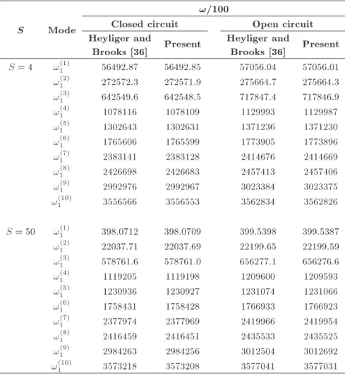
In order to have a comparison with other investiga-tions, the cylindrical bending vibration of a two-layer piezoelectric laminate is considered in this section. The laminate is composed of two dissimilar piezoelectric materials A and B. Both layers of the laminate have equal thicknesses and the total thickness is h = 0:01 m. For the length-to-thickness ratio, two values S(L=h) = 4 and S = 50 are considered. The present two-layer piezoelectric laminate has also been studied by Heyliger and Brooks [36]. The resulting natural frequencies (!n(j)) are shown in Table 1 for both Open Circuit (OC)
and Closed Circuit (CC) electric boundary conditions. The results are given in terms of natural frequencies in radian per seconds. In this table, the present results have been compared with those obtained by Heyliger and Brooks [36]. It can be observed that the present results are in excellent agreement with exact solutions of Heyliger and Brooks [36].
4.2. Example 2
In this example, free vibration of a single layer FGP strip with the thickness h = 0:001 m and length-to-thickness ratio S = 5 (thick strip) is considered. The considered strip is made of a PZT-4 based exponen-tially graded piezoelectric material with the following material properties:
cml = c0mlf(x3); eim= e0imf(x3);
ij = 0ijf(x3); = 0f(x3);
where:
f(x3) = eax3=h; 0 < x3< 0:001;
and a is a constant characterizing the degree of the material gradient along x3. c0ml, e0im, 0ij, and 0are the
values of material properties at the plane x3= 0. The
mechanical and electrical properties of the employed PZT-4 are the same as those cited in [13]. The strip is simply supported along two edges. The bottom plane of the FGP strip is assumed to be grounded (zero potential).
The natural frequencies (!n(j)) of thick FGP strip
with OC electric boundary conditions have been cal-culated for n = 1; 2; 3; :::. The lowest 12 natural frequencies are shown in Table 2 for three dierent material gradient indexes 1, 0, and -1. Homogeneous piezoelectric material is recovered for a = 0. It
Table 1. Natural frequencies of the two-layer piezoelectric laminated plate.
S Mode
!=100
Closed circuit Open circuit Heyliger and
Brooks [36] Present
Heyliger and
Brooks [36] Present S = 4 !(1)1 56492.87 56492.85 57056.04 57056.01 !(2)1 272572.3 272571.9 275664.7 275664.3 !(3)
1 642549.6 642548.5 717847.4 717846.9
!(4)
1 1078116 1078109 1129993 1129987
!(5)1 1302643 1302631 1371236 1371230
!(6)1 1765606 1765599 1773905 1773896
!(7)1 2383141 2383128 2414676 2414669 !(8)
1 2426698 2426683 2457413 2457406
!(9)
1 2992976 2992967 3023384 3023375
!1(10) 3556566 3556553 3562834 3562826
S = 50 !(1)1 398.0712 398.0709 399.5398 399.5387 !(2)1 22037.71 22037.69 22199.65 22199.59 !(3)
1 578761.6 578761.0 656277.1 656276.6
!(4)
1 1119205 1119198 1209600 1209593
!(5)1 1230936 1230927 1231074 1231066
!(6)1 1758431 1758428 1766933 1766923
!(7)1 2377974 2377969 2419966 2419954 !(8)1 2416459 2416451 2435533 2435525 !(9)
1 2984263 2984256 3012504 3012692
!(10)
1 3573218 3573208 3577041 3577031
Figure 2. The lowest frequency versus the number of terms in series solution.
gives a better insight about the eect of continuous through-the-thickness variations of material properties on the natural frequencies of piezoelectric laminates. In Table 2, the mode shapes are dened as Bend and Th for bending and thickness modes, respectively. Figure 2 shows the changes of the lowest frequency of the thick FGP strip with respect to the number of employed terms in calculation of the propagator matrix (Eq. (15)). It is seen from Figure 2 that
Figure 3. Functionally graded piezoelectric plate; mesh with 1000 elements (ABAQUS).
the proposed Peano series solution has a fast speed of convergence. Twenty terms in the series solution (Eq. (15)) are enough to get satisfactory accuracy for the lowest frequency. The same study is performed using ABAQUS with 8-node bi-quadratic plane strain elements. To this end, the thickness of the FGP strip was discretized into several thin homogeneous layers with dierent electrical and mechanical material properties. The mesh with 1000 elements (9423 dofs) as showed in Figure 3 yields converged results. For solving the eigenvalue problem, the Lanczos method available in the software was employed. In Table 2, the results of ABAQUS software have also been shown and compared with the present results. It is observed that the natural frequencies predicted by the proposed exact solution are in very good agreement with the ABAQUS results. For dierent values of material gradient index,
Table 2. Open circuit natural frequencies of the single-layer FGP strip (S = 5).
Material Natural frequencies (Hz) gradient
index Mode Present ABAQUS Dierence(%) a = 1 !(1)1 (Bend) 62758 62757 0.00
!(1)2 (Bend) 216733 216722 0.01 !(2)
1 (Th) 371672 371674 0.00
!(1)
3 (Bend) 413050 413018 0.01
!(1)
4 (Bend) 625720 625661 0.01
!(2)
2 (Th) 714830 714831 0.00
!(1)
5 (Bend) 843644 843560 0.01
!(2)3 (Th) 1013799 1013780 0.00
!(3)1 (Th) 1019253 1019140 0.01
!(1)6 (Bend) 1062100 1062000 0.01
!(3)2 (Th) 1210273 1210160 0.01
!(2)4 (Th) 1243814 1243750 0.01 a = 0 !(1)1 (Bend) 64028 64028 0
!(1)2 (Bend) 220065 220063 0.00 !(2)1 (Th) 372330 372330 0 !(1)
3 (Bend) 419038 419039 0.00
!(1)
4 (Bend) 635329 635332 0.00
!(2)
2 (Th) 714699 714699 0
!(1)
5 (Bend) 857713 857722 0.00
!(2)
3 (Th) 1007303 1007300 0.00
!(3)1 (Th) 1007831 1007830 0.00
!(1)6 (Bend) 1081314 1081340 0.00
!(3)2 (Th) 1204103 1204100 0.00
!(2)4 (Th) 1226441 1226440 0.00
a = 1 !(1)1 (Bend) 62287 61752 0.87 !(1)2 (Bend) 213170 211904 0.60 !(2)1 (Th) 373381 371123 0.61 !(1)
3 (Bend) 405167 403447 0.43
!(1)
4 (Bend) 614010 611996 0.33
!(2)
2 (Th) 719613 714130 0.77
!(1)
5 (Bend) 828620 826375 0.27
!(2)
3 (Th) 1019283 1011130 0.81
!(3)1 (Th) 1019456 1017660 0.18
!(1)6 (Bend) 1043843 1041390 0.24
!(3)2 (Th) 1219363 1214640 0.39
!(2)4 (Th) 1251246 1244150 0.57
the maximum discrepancy between the present results and those obtained from 2D nite element results is about 1%. The analytically obtained rst 12 mode shapes for S = 5 and electrically open circuit boundary conditions are shown in Figure 4. Although the strip
Figure 4. The rst twelve mode shapes of the simply supported FGP plate with a = 1; OC electric boundary conditions (S = 5).
Figure 5. Eect of L=h on the rst four fundamental frequencies of FGP plates with a = 1.
is assumed to be of innite width in the x2-direction,
the mode shapes are depicted in the 2D space for the purpose of illustration. It can also be observed from Table 2 that with increase in the absolute values of material gradient index a, the natural frequencies of the FGP strip decrease. The intensity of this phenomenon is more dominant in case of negative values of a.
Figure 5 addresses the eect of the aspect ratio S on the rst four natural fundamental frequencies of FGP strips. The material gradient index is a = 1 and the electric boundary condition is assumed to be OC. A sharp decrease in the natural frequency occurs for the thick FGP strips. This eect is particularly dominant for the fourth fundamental natural frequency. For S > 40, the sensitivity to the aspect ratio decreases regardless of the modes of vibration.
4.3. Example 3
The free vibration of a two-layer FGP laminate with the thickness h = 0:001 m and length-to-thickness ratio S = 5 is considered in this section. The lower layer is made of a homogeneous PZT-4 piezoelectric material. The upper layer is a PZT-4 based exponentially graded piezoelectric layer with the following material proper-ties:
Table 3. Open circuit natural frequencies of the two-layer FGP laminate (S = 5).
Material Natural frequencies (Hz) gradient
index Mode Present ABAQUS Dierence(%) a = 1 !(1)1 (Bend) 63533 63523 0.02
!(1)2 (Bend) 218457 218426 0.01 !(2)
1 (Th) 371629 371632 0.00
!(1)3 (Bend) 414998 414942 0.01
!(1)4 (Bend) 627333 627255 0.01 !(2)
2 (Th) 713768 713780 0.00
!(1)5 (Bend) 844648 844552 0.01
!(3)1 (Th) 1008885 1008910 0.00 !(2)
3 (Th) 1001648 1001680 0.00
!(1)6 (Bend) 1062433 1062330 0.01 !(3)
2 (Th) 1193562 1193590 0.00
!(2)4 (Th) 1231372 1231410 0.00
a = 1 !(1)
1 (Bend) 61894 61812 0.13
!(1)2 (Bend) 212853 212788 0.03
!(2)1 (Th) 373323 371300 0.54 !(1)
3 (Bend) 406136 406171 0.01
!(1)4 (Bend) 617253 617245 0.00
!(2)
2 (Th) 719610 713674 0.83
!(1)5 (Bend) 834935 834535 0.05
!(2)3 (Th) 1020619 1008030 1.25 !(3)
1 (Th) 1033281 1031640 0.16
!(1)6 (Bend) 1053974 1052620 0.13
!(3)2 (Th) 1231906 1227590 0.35 !(2)
4 (Th) 1236021 1236570 0.04
ij = 0ijf(x3); = 0f(x3);
where:
f(x3) = ea(x3 0:0002)=h; 0:0002 < x3< 0:001:
The ratio of the upper graded layer to the lower ho-mogeneous layer has been taken as 4. It is pointed out that c0
ml, e0im, 0ij, and 0 in the present example are
the values of material properties at the bottom of the top layer. Concerning the material property gradient index a, two values a = 1 and a = 1 are chosen. The rst 12 natural frequencies of the thick two-layer FGP laminate are shown in Table 3 for dierent values of aspect ratio. The assumed electric boundary condition is OC. Similar to the previous example, the obtained numerical results have been compared with the results obtained from 2D nite element analysis. Again, the agreement between the present and ABAQUS results is very good. The maximum percent of discrepancy
Table 4. Closed circuit natural frequencies of the two-layer FGP laminate (S = 5).
Material Natural frequencies (Hz) gradient
index Mode Present ABAQUS Dierence(%) a = 1 !(1)1 (Bend) 62931 62924 0.01
!(1)2 (Bend) 215069 215050 0.01 !(2)
1 (Th) 347985 347981 0.00
!(1)3 (Bend) 407260 407231 0.01
!(1)4 (Bend) 615244 615212 0.01 !(2)
2 (Th) 680080 680079 0.00
!(1)5 (Bend) 828704 828679 0.00
!(2)3 (Th) 973543 973557 0.00 !(3)
1 (Th) 987965 988002 0.00
!(1)6 (Bend) 1042972 1042970 0.00 !(3)
2 (Th) 1159873 1159910 0.00
!(2)4 (Th) 1201829 1201860 0.00
a = 1 !(1)
1 (Bend) 61746 61683 0.10
!(1)2 (Bend) 212846 212785 0.03
!(2)1 (Th) 348150 345341 0.81 !(1)
3 (Bend) 405919 405945 0.01
!(1)4 (Bend) 616408 616407 0.00
!(2)
2 (Th) 681632 675111 0.97
!(1)5 (Bend) 833480 833114 0.04
!(2)3 (Th) 979999 968180 1.22 !(3)
1 (Th) 1018076 1016880 0.12
!(1)6 (Bend) 1052145 1050870 0.12
!(3)2 (Th) 1186447 1182760 0.31 !(2)
4 (Th) 1218605 1201120 1.46
between the present and ABAQUS results is 1.25, whatever the values of the material gradient index.
The eect of electric boundary conditions, namely OC or CC, on the natural frequencies of the FGP laminates is illustrated in Table 4. Compared with the results obtained in Table 3, one can observe that the OC electrical boundary conditions lead to slightly higher natural frequencies regardless of the material gradient index. This eect, which is related to the piezoelectric coupling, is very well-captured by the present exact state-space formulation. The higher modes of vibration are more sensitive to the electric boundary conditions on the top and bottom planes of the FGP laminate than the lower modes. For example, for a = 1, the thickness mode natural frequency !4(2) changes by 29543 Hz depending on whether it is electrically closed or open. In comparison, the fundamental frequency !1(1) changes only by 602 Hz.
Figure 6. Distributions of ~u1, ~u3, ~11, ~33, ~13, ~D3, and ~' along the thickness of the simply supported two-layer FGP
plate in the rst bending mode (open circuit conditions); S = 5.
of modal entities ~u1, ~u3, ~11, ~33, ~13, ~D3, and ~'
at the dierent sections of the thick two-layer FGP laminate in the rst bending mode. For the material gradient index, three dierent values of 1, 0, and -1 are considered. The top plane of the graded laminate is electrically open while its bottom plane is grounded
(OC). The modal entities are normalized as follows: (~u1; ~u3; ~11; ~33; ~13; ~D3; ~')
= (u1; u3; 11; 33; 13; D3; ')= max(u1; u3):
results. It can be observed from Figure 6 that the dis-tributions of modal entities obtained from the present exact formulation are in excellent agreement with the ABAQUS results. Figure 6 also shows that the gradient index a inuences the distribution of modal stresses, displacements, electric potential, and transverse elec-tric displacement in dierent degrees. The value of a has little inuence on the distribution of the modal displacement components and the transverse electric displacement; however, it inuences the distribution of the induced electric potential and stress components, eectively. For a = 1, the maximal absolute value of
~
' is 64% larger than that of a = 1. The maximal absolute value of ~13 in the FGP laminate with a = 1
is 2 times as large as that with a = 1. This value for ~33 is 6.35.
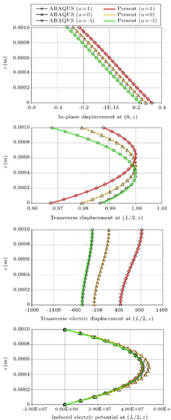
In order to see the eect of electric boundary con-ditions on the modal entities, the distributions of ~u1,
~u3, ~D3and ~' along the thickness of the thick two-layer
FGP laminate with CC electric boundary conditions in the rst bending mode are depicted in Figure 7. It is seen from Figure 7 that the electric boundary conditions have little inuence on the distribution of the modal displacement components. They also have little inuence on the distribution of the modal stress components. For the sake of brevity, the corresponding results have not been shown here. However, electric boundary conditions inuence the distribution of the modal electric potential and the transverse electric displacement, eectively.
4.4. Example 4
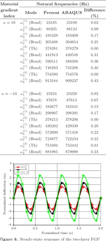
In order to assess the accuracy of the present 3D solution for dynamic analysis of FGP laminates with high values of gradient indices, free vibration of a
single-layer FGP strip with a = 10 and a = 10
is considered in this example. The thickness of the considered strip is h = 0:001 m and its length-to-thickness ratio is assumed to be S = 5. Boundary conditions, geometry, and other material properties of the FGP strip of the present example are the same as those of Example 2. The rst 10 natural frequencies of the FGP strip are shown in Table 5. The assumed electric boundary condition is OC. In this table, the obtained numerical results of the present example have been compared with the results obtained from 2D nite element analysis. It can be observed that the present results are in excellent agreement with 2D nite element results. The maximum percent of discrepancy between the present and ABAQUS results is 0.43. 4.5. Example 5
As a nal example, the steady-state response of a two-layer FGP laminate with length-to-thickness ratio due to harmonic mechanical and electrical loads is studied in this section. Boundary conditions, geometry, and
Figure 7. Through-the-thickness distributions of ~u1, ~u3,
~
D3, and ~' in the two-layer FGP plate in the rst bending
mode (close circuit conditions); S = 5.
material properties of the two-layer FGP laminate of the present example are the same as those of Exam-ple 3. The top plane of the FGP laminate was rst applied under the action of the harmonic distributed force 33(x1; h; t) = q0(sin 4000)(sin x1=L). The
Table 5. Open circuit natural frequencies of the single-layer FGP strip with high values of the material gradient index (S = 5).
Material Natural frequencies (Hz) gradient
index Mode Present ABAQUS Dierence(%) a = 10 !(1)1 (Bend) 23185 23180 0.02
!(1)2 (Bend) 88205 88124 0.09
!(1)3 (Bend) 185329 185009 0.17 !(1)4 (Bend) 305408 304654 0.25 !(2)
1 (Th) 378281 378279 0.00
!(1)
5 (Bend) 441913 440548 0.31
!(1)6 (Bend) 590511 588388 0.36
!(1)7 (Bend) 748283 745288 0.40 !(2)2 (Th) 754580 754576 0.00 !(1)
8 (Bend) 913184 909237 0.43
a = 10 !(1)1 (Bend) 23224 23220 0.02
!(1)2 (Bend) 87678 87615 0.07
!(1)3 (Bend) 182677 182441 0.13 !(1)4 (Bend) 298907 298391 0.17 !(2)
1 (Th) 378213 378206 0.00
!(1)
5 (Bend) 430202 429339 0.20
!(1)6 (Bend) 572699 571458 0.22
!(1)7 (Bend) 723877 722254 0.22
!(2)2 (Th) 753494 753442 0.01 !(1)8 (Bend) 881985 879998 0.23
Figure 8. Steady-state response of the two-layer FGP plate subjected to a harmonic distributed mechanical force; central deection.
top and bottom planes of the laminate are assumed to be grounded. The time history response of the normalized central deection of the FGP laminate is shown in Figure 8 for three values of the material
gradient index a = 1, a = 0, and a = 1. The
normalized values of deection and time are given as
Figure 9. Central deection of the two-layer FGP plate subjected to a harmonic distributed electric potential.
u3= u3 1010=q0 and t = t 103. It can be observed
from Figure 8 that the deection of the laminate made of soft gradient materials is higher than that of the laminate made of hard gradient materials. For a = 1, the peak deection of the FGP laminate is 2.02 times as large as that for a = 1. Due to the fact that the electromechanical stiness of a graded laminate made of hard piezoelectric materials is higher than that of a soft one, such behaviors are expected.
In the next case, the harmonic distributed elec-tric potential '(x1; h; t) = '0(sin 4000)(sin x1=L)
is applied on the top plane of the FGP laminate. The bottom plane of the laminate is assumed to be
grounded. The normalized central deection (u3 =
u3 1010='0) of the FGP laminate with respect to
normalized time (t = t 103) is shown in Figure 9
for dierent values of the material gradient index. The depicted graphs in Figure 9 reveal this fact that under a similar electric force, the transverse deection of an FGP laminate is much higher than that of a monomorph one (a = 0). This example shows that by employing the FGP actuators, it is possible to generate larger deections in the host structures.
5. Conclusions
In the present paper, a Peano series solution is em-ployed to investigate free vibration of FGP laminates. The presented series solution exactly satises the 3D theory equations of piezoelasticity. Unlike the avail-able reported methods which consider the FGP layer as a number of homogeneous sub-layers, the present formulation considers FGP layers as a transversely nonhomogeneous material. For validation, some com-parisons have been made with the results obtained from the coupled 2D nite element analysis. Excellent agreements have been found between the numerical results obtained from the present exact formulation and those obtained from the 2D nite element analysis.
Through dierent examples, the inuences of dierent functionally gradient material properties and dierent electric boundary conditions on the natural frequencies, modal entities, and mode shapes of the FGP laminates have been studied. The obtained numerical results of the present study give a comprehensive insight into the vibration behavior of the FGP laminates. Moreover, the presented numerical results are new and can be used by researchers as a benchmark for validating dierent FGP beam/plate theories.
References
1. Beheshti-Aval, S.B. and Lezgy-Nazargah, M. \A nite element model for composite beams with piezoelectric layers using a sinus model", J. Mech., 26(2), pp. 249-258 (2010).
2. Heyliger, P.R. and Saravanos, D.A. \Coupled discrete-layer nite elements for laminated piezoelectric plates", Commun. Numer. Methods Eng., 10(12), pp. 971-981 (1994).
3. Saravanos, D.A. and Heyliger, P.R. \Coupled layer-wise analysis of composite beams with embedded piezoelectric sensors and actuators", J. Intell. Mater. Syst. Struct., 6, pp. 350-363 (1995).
4. Tzou, H.S. and Gadre, M. \Theoretical analysis of a multi-layered thin shell coupled with piezoelectric shell actuators for distributed vibration controls", J. Sound Vib., 132, pp. 433-450 (1989).
5. Beheshti-Aval, S.B. and Lezgy-Nazargah, M. \As-sessment of velocity-acceleration feedback in optimal control of smart piezoelectric beams", Smart. Struct. Syst., 6(8), pp. 921-938 (2010).
6. Beheshti-Aval, S.B., Lezgy-Nazargah, M., Vidal, P. and Polit, O. \A rened sinus nite element model for the analysis of piezoelectric laminated beams", J. Intell. Mater. Syst. Struct., 22, pp. 203-219 (2011).
7. Beheshti-Aval, S.B. and Lezgy-Nazargah, M. \A cou-pled rened high-order global-local theory and nite element model for static electromechanical response of smart multilayered/sandwich beams", Arch. Appl. Mech., 82(12), pp. 1709-1752 (2012).
8. Beheshti-Aval, S.B. and Lezgy-Nazargah, M. \Coupled rened layerwise theory for dynamic free and forced response of piezoelectric laminated composite and sandwich beams', Meccanica, 48(6), pp. 1479-1500 (2013).
9. Beheshti-Aval, S.B., Shahvaghar-Asl, S., Lezgy-Nazar-gah, M. and Noori, M. \A nite element model based on coupled rened high-order global-local theory for static electromechanical analysis of embedded shear mode piezoelectric sandwich composite beams", Thin Walled Struct., 72, pp. 139-163 (2013).
10. Niezrecki, C., Brei, D., Balakrishnan, S. and Moskalik, A. \Piezoelectric actuation: State of the art", Shock Vib. Dig., 33(4), pp. 269-280 (2001).
11. Ray, M.C. \Micromechanics of piezoelectric compos-ites with improved eective piezoelectric constant", Int. J. Mech. Mater. Des., 3, pp. 361-371 (2006).
12. Lezgy-Nazargah, M. \A micromechanics model for eective coupled thermo-electro-elastic properties of macro ber composites with interdigitated electrodes", J. Mech., 31(2), pp. 183-199 (2015).
13. Doroushi, A., Eslami, M.R. and Komeili, A. \Vibra-tion analysis and transient response of an FGPM Beam under thermo-electro-mechanical loads using higher-order shear deformation theory", J. Intell. Mater. Syst. Struct., 22, pp. 231-243 (2011).
14. Lezgy-Nazargah, M. and Farahbakhsh, M. \Optimum material gradient composition for the functionally graded piezoelectric beams", Int. J. Eng. Sci. Tech., 5(4), pp. 80-99 (2013).
15. Lezgy-Nazargah, M., Vidal, P. and Polit, O. \An ecient nite element model for static and dynamic analyses of functionally graded piezoelectric beams", Compos. Struct., 104, pp. 71-84 (2013).
16. Zhu, X.H. and Meng, Z.Y. \Operational principle, fabrication and displacement characteristic of a func-tionally gradient piezoelectric ceramic actuator", Sens. Actuators A., 48, pp. 169-176 (1995).
17. Wu, C.C.M., Kahn, M. and Moy, W. \Piezoelectric ceramics with functional gradients: A new application in material design", J. Am. Ceram. Soc., 79, pp. 809-812 (1996).
18. Yang, J. and Xiang, H.J. \Thermo-electro-mechanical characteristics of functionally graded piezoelectric ac-tuators", Smart Mater. Struct., 16, pp. 784-797 (2007).
19. Behjat, B., Salehi, M., Sadighi, M., Armin, A. and Ab-basi, M. \Static, dynamic, and free vibration analysis of functionally graded piezoelectric panels using nite element method", J. Intell. Mater. Syst. Struct., 20, pp. 1635-1646 (2009).
20. Behjat, B., Salehi, M., Armin, A., Sadighi, M. and Abbasi, M. \Static and dynamic analysis of function-ally graded piezoelectric plates under mechanical and electrical loading", Scientia Iranica. Transactions B: Mech. Eng., 18(4), pp. 986-994 (2011).
21. Wu, X.H., Chen, C.Q. and Shen, Y.P. \A high order theory for functionally graded piezoelectric shells", Int. J. Solids Struct., 39, pp. 5325-5344 (2002).
22. Brischetto, S. and Carrera, E. \Rened 2D models for the analysis of functionally graded piezoelectric plates", J. Intell. Mater. Syst. Struct., 20, pp. 1783-1797 (2009).
23. Lee, H.J. \Layerwise laminate analysis of functionally graded piezoelectric bimorph beams", J. Intell. Mater. Syst. Struct., 16, pp. 365-371 (2005).
24. Lu, P., Lee, H.P. and Lu, C. \An exact solution for functionally graded piezoelectric laminates in cylin-drical bending", Int. J. Mech. Sci., 47, pp. 437-458 (2005).
25. Reddy, J.N. and Cheng, Z.Q. \Three-dimensional solutions of smart functionally graded plates", ASME J. Appl. Mech., 68, pp. 234-241 (2001).
26. Liu, G.R. and Tani, J. \Surface waves in functionally gradient piezoelectric plates", ASME J. Vib. Acoust., 116, pp. 440-448 (1994).
27. Chen, W.Q. and Ding, H.J. \On free vibration of a functionally graded piezoelectric rectangular plate", Acta Mech., 153, pp. 207-216 (2002).
28. Li, Y. and Shi, Z. \Free vibration of a functionally graded piezoelectric beam via state-space based dier-ential quadrature", Compos. Struct., 87, pp. 257-264 (2009).
29. Zhong, Z. and Shang, E.T. \Three-dimensional exact analysis of a simply supported functionally gradient piezoelectric plate", Int. J. Solids Struct., 40, pp. 5335-5352 (2003).
30. Lu, P., Lee, H.P. and Lu, C. \Exact solutions for simply supported functionally graded piezoelectric laminates by Stroh-like formalism", Comput. Struct., 72, pp. 352-363 (2006).
31. Liu, T.T. and Shi, Z.F. \Bending behavior of function-ally gradient piezoelectric cantilever", Ferroelectrics., 308, pp. 43-51 (2004).
32. Shi, Z.F. and Chen, Y. \Functionally graded piezoelec-tric cantilever beam under load", Arch. Appl. Mech., 74, pp. 237-247 (2004).
33. Xiang, H.J. and Shi, Z.F. \Static analysis for func-tionally graded piezoelectric actuators or sensors under a combined electro-thermal load", Eur. J. Mech. A Solids, 28, pp. 338-346 (2009).
34. Lim, C.W. and He, L.H. \Exact solution of a com-positionally graded piezoelectric layer under uniform stretch, bending and twisting", Int. J. Mech. Sci., 43, pp. 2479-2492 (2001).
35. Lezgy-Nazargah, M. \A three-dimensional exact state-space solution for cylindrical bending of continuously non-homogenous piezoelectric laminated plates with
arbitrary gradient composition", Arch. Mech., 67(1), pp. 25-51 (2015).
36. Heyliger, P. and Brooks, S. \Free vibration of for piezoelectric laminates in cylindrical bending", Int. J. Solid Struct., 32(20), pp. 2945-2960 (1995).
37. Gantmakher, F.R., The Theory of Matrices, Chelsea, New York (1959).
38. Pease, M.C., Methods of Matrix Algebra, Academic Press, New York (1965).
39. Alshits, V.I., Kirchner, H.O.K. and Maugin, G.A. \Elasticity of multilayers: properties of the propagator matrix and some applications", Math. & Mech. Sol., 6(5), pp. 481-502 (2001).
Biography
Mojtaba Lezgy-Nazargah received the BS degree in Civil Engineering from Shahrood University of Tech-nology, Shahrood, Iran, in 2006. He received his MS and PhD degrees in Civil and Structural Engineering from K.N. Toosi University of Technology, Tehran, Iran, in 2008 and 2011, respectively. He has been working as Assistant Professor in the Civil Engineering Department at Hakim Sabzevari University, Sabzevar, Iran, since 2011. His major research interests include computational mechanics, active vibration control of structures, smart materials and structures, laminated composite structures, and nonlinear analysis of steel and reinforced concrete structures. He has published more than 18 papers in the international journals. He has also written a book on design of reinforced concrete structures in Persian. Dr. Lezgy-Nazargah has supervised 16 MS research works in his research areas. He teaches courses on Static, Mechanics of Ma-terials, Finite Element Analysis, Theory of Elasticity, Plates and Shells, and Design of Reinforced Concrete Structures.