R E V I E W
Open Access
Review of protection and fault handling for
a flexible DC grid
Jinghan He, Keao Chen, Meng Li
*, Yiping Luo, Chenguang Liang and Yin Xu
Abstract
With the development of power electronics technology, the flexible DC grid will play a significant role in promoting the transformation and reformation of the power grid. It is immune to commutation failure and has high flexibility in power control and renewable energy grid integration. However, the protection and fault handling technology for a flexible DC grid is a big challenge because of the limited overcurrent capability of the converters. This paper summarizes the development of the flexible DC grid, and analyzes the fault characteristics in detail. Next, the applicability, advantages and disadvantages of the existing protection principle, fault isolation and recovery schemes are reviewed. Finally, the key problems and development trend of the future flexible DC grid are pointed out and forecasted respectively.
Keywords:Flexible DC power grid, Fault analysis, Protection, Fault isolation, Reclose
1 Introduction
With the depletion of fossil energy, the worsening envir-onmental pollution, and the occurrence of extreme cli-mate events, large-scale development of renewable energy has become a significant trend around the world [1]. However, wind, solar and other renewable energy are intermittent and random. Meanwhile, the local ab-sorption capability of renewable energy is limited, mak-ing the phenomenon of abandonmak-ing wind and solar energy is very common [2]. Because of its advantages of flexible active and reactive power control and low trans-mission loss, the flexible DC grid has become one of the most important parts to solve the above problems. The first DC grid demonstration project has been in con-struction in Zhangbei, China.
Compared with traditional DC technology using line commutated converters (LCC), flexible DC technology with voltage source converters (VSC) is immune to com-mutation failure, which has decoupled active and react-ive power control with no need for filtering and reactreact-ive compensation, and can also supply power to isolated islands [3, 4]. In brief, such a flexible DC grid has
numerous additional advantages including: (1) Multiple power supplies and receivers improve the overall stabil-ity of the power grid. (2) Network operation can reduce the number of converter stations and investment costs of transmission corridors. (3) It provides a more secure and flexible operation mode, which can guarantee power transmission under an n-1 condition.
The protection and fault handling of conventional LCC HVDC transmission systems and two-terminal flex-ible HVDC transmission systems are relatively mature. For the former, when a fault occurs, the thyristors in the LCC have high endurance to overcurrent, and the firing angle can also be controlled to limit the fault current. For the latter, although IGBTs are vulnerable, the con-verters can block the submodules quickly to protect the component-level equipment with no high requirement for selectivity. However, the flexible DC grid has differ-ent fault characteristics and thus brings high require-ments on both protection speed and selectivity. Therefore, there are some important challenges in pro-tection and fault handling in the flexible DC grid as follows:
(1) The transient process after a fault is complicated and difficult to calculate accurately. However,
© The Author(s). 2020Open AccessThis article is licensed under a Creative Commons Attribution 4.0 International License, which permits use, sharing, adaptation, distribution and reproduction in any medium or format, as long as you give appropriate credit to the original author(s) and the source, provide a link to the Creative Commons licence, and indicate if changes were made. The images or other third party material in this article are included in the article's Creative Commons licence, unless indicated otherwise in a credit line to the material. If material is not included in the article's Creative Commons licence and your intended use is not permitted by statutory regulation or exceeds the permitted use, you will need to obtain permission directly from the copyright holder. To view a copy of this licence, visithttp://creativecommons.org/licenses/by/4.0/.
* Correspondence:mengl@bjtu.edu.cn
analysis of fault characteristics by stages is the basis of component design and protection research. (2) The conventional protection principle in simple and
special scenarios is insufficient to meet the
requirement in complex network for the speed and selectivity of protection. Therefore, a practical analysis of the classification of the existing protection principle is important.
(3) Fast and effective fault isolation in a flexible DC grid is challenging, and the ideal situation is to use DC circuit breakers to isolate the fault section. Therefore, the development of highly efficient and economical DCCBs can bring a major breakthrough to DC grid development.
(4) Rapid system recovery after a fault is an important measure to ensure continuous transmission of electrical energy. Studying the reclosing strategy applicable to a flexible DC grid can significantly improve the reliability of system operation.
This paper starts with the development background of HVDC transmission systems, then reviews the protec-tion and fault handling from the aspects of fault analysis, protection principle, fault isolation and fault recovery, and finally illustrates future development directions.
2 Overview of flexible DC technology
HVDC transmission technology based on LCC has the disadvantages of being susceptible to commutation fail-ure, absorbing a large amount of reactive power and having no ability to supply power to passive networks. In order to solve these problems, a flexible DC
transmission technology based on VSC was proposed. Flexible DC projects have undergone 2 generations of technological development. In the first generation, two-level and three-two-level VSC converters were used. The converter valve is composed of IGBTs in series, resulting in many problems including difficulty in voltage sharing, high switching loss, and high harmonic content. A modular multi-level converter (MMC) topology [5] was proposed by R. Marquart in 2001. This has the advan-tages of low manufacturing difficulty and low loss, lead-ing to the second generation of flexible DC technology. A number of MMC topologies with DC fault current suppression capability have also been proposed.
By 2019, 44 flexible DC transmission projects have been put into operation all over the world with a total transmission capacity of 35,084.2 MW, and there are also 7 projects under construction. Table 1 shows some of the projects.
The flexible DC grid is expected to become the back-bone of building a new generation of smart grid [2, 4]. The U.S. has proposed the plan of building a national power backbone network connecting the East and the West, from Mexico in the south to Canada in the north. Europe has also proposed the building of an intercon-nected flexible DC grid from the North Sea to the north-ern part of the European continent to achieve the mutual complementarity of multiple renewable energy sources across Europe. In China, five flexible DC pro-jects have been completed, and the world’s first demon-stration project with a voltage level of ±500 kV will be put into operation in 2020. The rest of the paper is based on this Zhangbei 4-terminal HVDC system as
Table 1Typical VSC-HVDC transmission projects
Project Name Country Time PN/MW U/kV Transmission distance/km
Gotland Sweden 1999 54 ±80 70
Eagle Pass B2B U.S.A-Mexico 2000 36 ±15.9 0
Cross Sound Cable U.S.A 2002 330 ±150 40
Estlink Estonia-Finland 2006 350 ±150 105
Valhall offshore Norway 2009 78 ±150 292
Trans Bay Cable U.S.A 2010 400 ±200 88
Shanghai Nanhui China 2011 18 ±30 8.6
Nan’ao China 2013 200 ±160 40.7
Zhoushan China 2014 1000 ±200 140.1
Xiamen China 2015 1000 ±320 10.7
DolWin1 Germany 2015 800 ±320 165
Luxi China 2016 3000 ±500 0
Yu’e China 2019 5000 ±420 0
Zhangbei China 2020 9000 ±500 666
Wudongde China 2020 10,200 ±800 1489
shown in Fig. 1. With the development of technology and increasing demands, flexible DC projects are moving towards high voltage, high power configuration and multi-terminal networked structures.
3 Requirements of DC grid protection and fault handling research
The rapid development of flexible DC power transmis-sion, especially the increasing number of overhead line projects, brings high requirements for protection and fault handling technology. It not only needs to know the fault characteristics, but also needs to reveal the fault mechanism. In addition to being able to identify the faults, it is also necessary to isolate the faults and realize the recovery of the DC grid in an efficient way.
3.1 Analysis of fault characteristics
Analysis of fault characteristics is the basis for the devel-opment of a flexible DC grid. From the grid construction plan to accident analysis, from parameter design to equipment selection, from protection principles to par-ameter setting, all need to be supported by fault mecha-nisms. In AC systems, research on the fault mechanism is quite mature, but in the field of the flexible DC grid, the knowledge is far from being sufficient. Electromag-netic transient simulation can provide information on the fault characteristics but not the reason behind them. Therefore, for the long-term development of the flexible DC grid, understanding of fault mechanisms is a top priority.
3.2 Protection principle
The protection principle is the essential safeguard for the development of a flexible DC grid. If there is no ad-equate protection scheme, a single fault can lead to the shutdown of the entire DC grid. The first step of protec-tion should ensure that the power electronic devices are protected from damage. Secondly, the protection needs to be selective, with high reliability and sensibility to en-dure disturbances and varying fault resistance.
3.3 Fault clearing
Fault isolation is a key requirement of protection, and it is also a challenging task in DC technology. Unlike the fault current in an AC system, which has a natural zero crossing, breaking the DC fault current is challenging. The realization of efficient and economical fault isolation is the basis for the expansion of the DC grid.
3.4 Fault recovery
Fault recovery of the flexible DC grid needs to be intelli-gent and flexible, so as to minimize secondary impact for the operating grid. How to identify the permanent fault of a DC line and to reduce the influence of reclos-ing will be the key points.
Therefore, this paper will review the relay protection from the aspects of fault analysis, protection principle, fault isolation and fault recovery in the following sections.
4 DC fault analysis
DC fault analysis is the basis of component design and protection research. Existing researches of DC grid fault analysis mainly includes two aspects: 1) analysis of the DC fault development process, 2) analysis of the time-domain and frequency-time-domain characteristics of fault electrical quantities. Among them, the fault development process illustrates the dominant contributor of the fault current during each fault stage, while the time-domain and frequency-domain characteristics of the fault elec-trical quantities show the difference features between in-ternal faults and exin-ternal faults that can be used to construct protection criteria.
4.1 Analysis of the DC fault development process
4.1.1 Fault development process of the converter
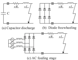
Existing research shows that the development process of a pole-to-pole fault of the two-level VSC [6] and MMC [7] can be divided into three stages: capacitor discharge, diode freewheeling and AC feeding, as depicted in Fig.2. Based on the division of the fault stages, scholars have further studied the converter’s fault equivalent circuit and fault current analytical expressions in each stage [8– 10]. In the capacitor discharge stage and the diode free-wheeling stage the converter can be equivalent to a second-order circuit and a first-order circuit [7, 11–17], respectively. During the AC feeding stage, the IGBT is blocked due to self-protection and the converter can be equivalent to an uncontrolled diode rectifier. References [18, 19] carried out a theoretical analysis of the fault mechanisms of two-level VSC and MMC during the AC feeding stage, dividing them into transient and steady-state phases. References [20–25] estimated the steady-state DC fault current based on the IEEE61660 standard, while [26, 27] used the external VI-characteristic of the Fig. 1Schematic diagram of Zhangbei 4-terminal
converter to obtain a more accurate value of the steady-state DC fault current. However, due to the non-linearity of the converter, the analytical expression of the transient fault current in the AC feeding stage has not yet been obtained [22–24,28].
4.1.2 Fault development process on the DC line
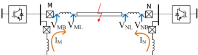
When a DC line fault occurs, the transient voltage and current traveling waves generated at the fault point propa-gate to both sides of the line, as shown in Fig.3. When these traveling waves reach the converter, they will be superimposed with the fault current generated by the con-verter, resulting in complex fault characteristics [29].
Efforts have been made to reveal the fault develop-ments on DC lines. Reference [30] analyzed the influ-ence of different line models on the transient fault current and determined the initial transient current for different network topologies. Reference [29] studied the effect of line distributed capacitance on fault currents. Considering boundary conditions, a single line fault current expression considering the line distribution pa-rameters was obtained in [31], while reference [32] stud-ied the influence of adjacent lines and obtained the expression for the transient fault current in multi-terminal DC girds. These methods are effective in deter-mining the initial transient fault current, but as the
number of traveling wave reflections increases, their ac-curacy decreases.
4.2 Time-domain and frequency-domain characteristics
4.2.1 Time-domain characteristics
The time-domain characteristics of fault voltage and current have three main types: amplitude characteristics, rate of change characteristics, and polarity characteristics.
Because of the discharging of the capacitor, the DC voltage drops and DC current rises in the first stage of the fault. For the DC voltage, as shown in Fig.3, ignor-ing the attenuation effect of the DC line and considerignor-ing the internal fault F1, the traveling wave generated by the
fault point will directly propagate to both ends of the line, and the DC voltageVm and Vnwill have a vertical
jump. However, when the external fault F2 occurs, the
traveling wave will first be attenuated by the reactor in-stalled at the end of the line, resulting in lower rates of change of Vm and Vn. Therefore, the rates of change of
DC voltages can be used to distinguish internal faults and external faults. By contrast, for DC fault current, its amplitude and change rate are not only influenced by the fault location but also the fault resistance, and thus cannot be used to construct the primary protection cri-teria. Nevertheless, the polarities of the fault current at different fault locations differ. In Fig. 3, for fault F1, the
direction of the fault current is from the bus to the DC line, which is opposite to that of the external fault F2.
Thus, this feature can be used to determine the fault direction.
4.2.2 Frequency-domain characteristics
In this section, the frequency-domain characteristics of the DC voltage, the DC fault current, and the differential current will be analyzed.
The multiple reflection process of traveling waves has brought complex fault transients to the DC voltage. In [28], the voltage of the DC bus during a metallic fault is analyzed by Fourier Transform, and the results show that the DC voltage contains significant high-frequency components. These high-frequency components can be easily blocked by the current limiting reactors, which makes the voltage of the internal faults and external faults present different frequency-domain characteristics. In [33,34], the expression of the ratio of the DC voltages across the current limiting reactor is obtained. The magnitude-frequency curve of the expression shows that the high-frequency component of the voltage is attenu-ated while the low-frequency component is strength-ened, and this feature can be used to distinguish the fault line.
Reference [30] analyzed the frequency-domain char-acteristics of the fault current at each fault stage, and presented the converter’s fault current waveforms and Fig. 2VSC and MMC converter fault equivalent circuits in
the three stages of the pole-to-pole fault
its frequency domain response, as shown in Fig. 3. It pointed out that the fault current before converter blocking is mainly the attenuated period component, whose frequency as given in (1) depends on the cap-acitor discharge circuit parameters. Also, because of the commutation of diodes, there will be a significant sixth harmonic component in the fault current after converter blocking. This can provide a theoretical basis for the construction of distance protection after blocking [31]
f ¼
ffiffiffiffiffiffiffiffiffiffiffiffiffiffiffiffiffiffiffiffiffiffiffiffiffiffiffiffiffiffiffiffiffiffi
1=LC
ð Þ−ðR=2LÞ2
q
2π ð1Þ
where, R, L, and C are the resistance, inductance, and the capacitance of the equivalent fault circuit, respectively.
The fault differential current of line MN in Fig. 1can be expressed as:
idiff ¼im−in ð2Þ
It is seen that for the external fault F2, the main
com-ponent of the differential current idiff is the distributed
capacitor discharge current, whose frequency is related to the natural frequency of the traveling wave and is usually higher than 1 kHz. Whereas for the internal fault F1, idiffis mainly the fault current, and its frequency
de-pends on the capacitor discharging circuit and is gener-ally below 1 kHz. Therefore, it is possible to use the frequency characteristics of the differential current to distinguish internal and external faults [35].
Research on the time-frequency characteristics of faults further reveal the differences between internal and exter-nal fault characteristics, which lays a good theoretical foundation for the establishment of fault identification cri-teria. However, these studies are mostly qualitative ana-lysis and lack of quantitative calculation of fault time and frequency quantities, thereby brings great difficulty in pro-tection setting.
5 Protection principle
The protection principle of flexible DC grid is a key point of the research. At present, the research on fault detection and identification of AC system is mature, but the fault characteristics of flexible DC grid are different. Therefore, the traditional AC protection principle is dif-ficult to be applied in flexible DC grid. On the one hand, the energy storage element in VSC makes the DC fault current rise rapidly; on the other hand, the network top-ology expands the influence range of DC faults. In addition, the vulnerability of power electronics equipment also makes the requirements for protection more strin-gent. The requirement of speed and selectivity of protec-tion principle have become two key issues that need to be
addressed in flexible DC grid. In the existing research, the protection methods of flexible DC grids can be roughly di-vided into several schemes of fault detection and identifi-cation such as traveling wave protection, voltage and current protection, boundary protection, pilot protection, and protection-control coordination protection.
5.1 Traveling wave protection
Traveling wave protection is commonly adopted in DC grids. When a DC line fault occurs, voltage and current traveling waves will be generated at the fault point and propagate to both sides of the line at approximately the speed of light. Due to its high speed, it has good applica-tion in practical engineering.
In engineering application, travelling wave protection is usually based on abundant characteristics, such as amplitude, polarity, propagation time. These electrical quantities can be extracted and analyzed by correspond-ing mathematical methods to detect or identify the fault. However, most corresponding protection schemes have no immunity to large transition resistance and noise disturbance.
In [36, 37], a traveling wave detection method based on two terminal electrical quantities was proposed. By calculating the time interval of traveling wave propaga-tion between two terminals, the fault type and locapropaga-tion can be accurately determined. However, it will be limited by communication delay, while compared with a trad-itional HVDC system, the flexible HVDC grids require a higher protection speed. A method based on rate of current change to identify fault section was proposed in [38, 39], but extreme cases like bus-bar fault can cause mal-operation and the reliability needs to be raised. Ref-erence [40] used the rate of voltage change to identify the fault, though the method has the problem of poor immunity to large transition resistance.
Traveling wave protection is widely used, mainly be-cause it has abundant fault information. In addition, the fault transient traveling wave propagates to the two ends of the line at the speed of light, which can enable high speed fault identification. However, the ability of im-munity to transition resistance, noise and lightning dis-turbance is poor. Reliability and sensibility are still not fully met in the flexible DC grid.
5.2 Voltage and current protection
When a short-circuit fault occurs on a DC line, it will cause some characteristic changes such as voltage drop and sharp current rise with oscillation. The voltage and current on both sides contain rich fault information, so the amplitude, change rate and polarity can be used as the basis for fault identification.
The rate of voltage change of the DC line is used in reference [44] for fault identification and location. However, the threshold setting needs to consider all faults in the protection area, and it is difficult to en-sure its selectivity. Reference [45] proposed a protec-tion scheme based on the overcurrent, which is only suitable for special DC systems such as low-voltage and small-scale micro-grids. Reference [46] proposed a DC line protection method that measures both the voltage differential value and the voltage amplitude level, which can be used as backup protection in a practical flexible DC project. Reference [47] also pro-posed a backup protection algorithm based on quick-change detection (QCD). The protection based on local information measurement is applicable to various scenarios. It can realize a fast and accurate backup protection function and ensure high system reliability.
The advantage of the detection method based on volt-age and current changes is that the fault characteristics can be better captured in the time domain or the fre-quency domain, and the operation speed is fast based on single terminal. Meanwhile, the scheme based on multi-point measurement of voltage and current can also raise the reliability. Therefore, it can be a suitable choice as the main or backup protection for a flexible DC grid. However, in a multi-terminal system, it is sometimes dif-ficult to ensure selectivity by only depending on the single-terminal electrical quantity, and it can be easily af-fected by some factors such as transition resistance.
5.3 Boundary protection
A large capacitor is configured in parallel at the DC side of two-level VSC and current limiting reactors are con-figured at the end of DC lines in MMC system, as shown in Fig. 4. The nature of boundary characteristic is when the fault occurs at one side of boundary, the fault char-acteristics measured has the significant difference
compared with another side. Usually, high-frequency component is impeded by the boundary. According to the results of spectrum analysis in Fig.5, the DC voltage contains a large high-frequency component.
It is more common to use the characteristics of the boundary conditions themselves, such as voltage infor-mation of inductor and current inforinfor-mation of capacitor, to extract fault characteristic quantities. The protection scheme constituted by the above ideas is called a transi-ent protection scheme based on boundary conditions. Reference [48] proposed an event-based multi-terminal protection scheme, in which each protection unit uses the transient current fault identification method and ar-tificially constructs line reactor to autonomously identify the event type. Compared with traditional data-based protection schemes, it does not need communication and clock synchronization, but it does depend on the de-signed structure of the boundary. Reference [49] pro-posed a fault detection method based on the first-order and second-order differentials of the transient DC fault current, but it can’t effectively identify high-impedance faults and has only been tested in a small scale DC grid. Reference [50] proposed a protection scheme based on the rate of the voltage change of the current-limiting re-actor. Since the rate of the inductor voltage change is the second derivative of the current, the protection method has a better ability to endure the transition re-sistance. Meanwhile, compared with the scheme based on rate of current change, the bus voltage is relatively unchanged at the beginning of the fault, so it can pro-vide a greater reliability of fault identification. It can quickly identify faults without the need for two-terminal communication, but the setting scheme is relatively complex. Reference [51] proposed a protection scheme using transient voltage on the DC transmission line. As the boundary of the DC line, the inductor provides a
Fig. 5Spectrum of DC voltage
high-impedance path for high-frequency component. This will cause a significant difference in the ratio of the transient voltage on both sides of the inductor in situa-tions of internal fault and external fault. Compared with the methods based on rate of voltage change and current change, it has superiority in sensibility and ability to en-dure transition resistance.
The boundary protection has stronger capability of im-munity to the disturbance of noise and large transition resistance. Meanwhile, this will not require additional equipment configured in the system. However, it also in-creases the complexity when the algorithm like wavelet is used to extract the high frequency component. More-over, transient quantities are susceptible to nonlinearity. In brief, single-ended boundary protection can be usu-ally used as one of the primary protection.
5.4 Pilot protection
Pilot protection can be divided into current differential protection and directional pilot protection. The current differential protection needs to detect the difference of current between the two ends of the line to identify the fault. The directional pilot protection uses the electrical quantities at both ends of the line as the basis for fault identification. The signal propagation will affect the speed of protection. In order to reduce the influence of communication delay on the speed of protection, refer-ence [52] shortens the signal propagation time by setting multiple photocurrent sensors on the DC line and adopts distributed detection of differential current to achieve high speed fault detection. It can effectively identify internal and external faults and provide backup for each other in the event of element failure to increase reliability, but the economic cost is high. Reference [53] uses the energy of the difference of current to decrease the influence of distributed capacitors, but the problem of protection delay still exists. Reference [54] takes the DC reactors at both ends of the line in the DC grid as the boundary, analyzing the difference in the transient characteristics of the DC voltage on both sides of the line between internal and external faults. But the high frequency component is extracted by wavelet algorithm, which increases the computation of protection. Refer-ence [55] uses a linear process after the moment of the fault to identify the internal and external faults based on the direction of the fault component. The protection has the advantage in speed, but it will be affected by nonlin-ear interference such as converter blocking. On this basis, reference [56] proposed a pilot protection scheme based on full current, which is no longer affected by non-linear processes and increases the reliability of protection.
To sum up, pilot protection in flexible DC grid will de-pend on the electrical quantities at both ends of the line,
and communication delay can’t be avoided, so the pro-tection speed has no superiority compared with single-ended protection. However, it has advantages on select-ivity and sensibility. Current differential protection and directional pilot protection can be backup protection, but directional pilot protection is also taken as primary protection under some situations.
5.5 Protection-control coordination
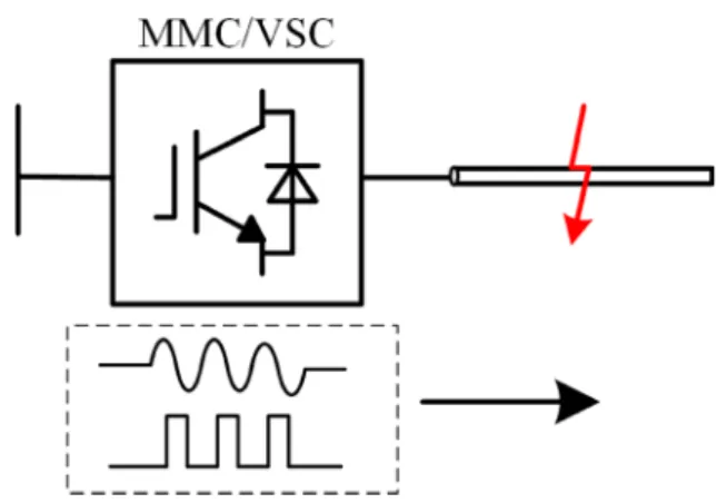
In a multi-terminal flexible DC grid, complex control can interfere with protection. However, the controllable characteristics of the converters can also be used to pro-vide a stable and reliable characteristic signal for protec-tion, thereby improving the reliability and accuracy of protection discrimination, as shown in Fig.6. It can also provide technical support for high speed and selective identification of faults.
Many studies have mentioned the use of highly con-trollable converters such as DC-DC and full-bridge MMC to detect and locate faults by injecting character-istic signals into the fault point after fault. Reference [57, 58] proposed controlling the switching mode by using the DC/DC boost converter to change the modulation frequency of the converter in a photovoltaic grid-connected DC system after fault. The converter at each port is transformed into an injection source with charac-teristic signal for fault calculation and detection. How-ever, it is only applicable to similar multiport DC aggregation systems and is difficult to apply to long-distance transmission systems. Reference [59] combined a half-bridge MMC and hybrid circuit breaker, and used the hybrid circuit breaker to actively inject a voltage pulse signal to the fault line to determine the fault prop-erty and achieve high speed restart. In [60], the MMC submodule control is changed briefly to inject voltage pulses into the DC line, and the fault location is achieved by measuring the pulse emission and arrival time. This method can be applied by both half-bridge and full-bridge MMC.
The research the above on fault detection and location methods by changing the control mode of converter is still in the preliminary stage, which can only be carried out in the steady state process after the fault, and it is difficult to meet the requirement of speed of protection. For multi-terminal systems, the port where the signal is generated and the type of signal should also be considered.
6 DC fault clearing
After identifying the faulty line accurately, it is also ne-cessary to quickly interrupt the fault current to avoid further damages. In AC systems, the fault current can be cleared by opening the mechanical switch at the zero-crossing point of the fault current. However, the DC sys-tem fault current does not have a zero-crossing point, which makes the DC fault clearing a major problem in DC system protection.
By now, scholars have carried out many studies on how to clear the DC fault current, and three types of DC fault interruption methods have been proposed: 1) using AC circuit breaker, 2) using DC circuit breaker, 3) using converters with fault current blocking capabilities.
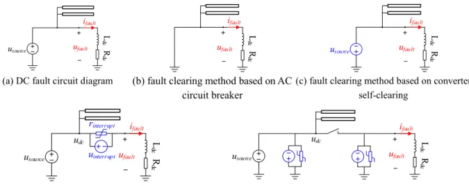
Once a fault occurs, the converter can be regarded as a huge fault power source (usource) and is continuing
dis-charging to the fault point, as shown in Fig. 7a. Accord-ing to Ohm’s law, the fault current (ifault) can be
reduced by reducing the fault voltage ufaultor by
increas-ing the resistance rfault. Correspondingly, there are two
approaches to realize DC fault clearing. One is the step-down of the fault source scheme (where the fault source is directly set to zero or negative voltage), and the other is the reverse blocking EMF (Electromotive Force, EMF) scheme (in which the fault sources still exists but a re-verse blocking EMF with an amplitude higher than that
of the fault source will be generated to interrupt the fault current). The three existing fault clearing methods are basically realized through these two approaches.
6.1 Approach 1: change the fault source
6.1.1 Fault clearing scheme based on AC circuit breaker In many commissioned DC projects, the DC fault clearing is realized using the AC circuit breaker [61]. After fault inception, the converters at both ends of the line are first blocked, and then the AC circuit breaker is opened at the zero-crossing point of the AC current, which is equivalent to setting the fault source ufault to zero, as shown in Fig. 7b. Finally, the
remaining fault energy will be dissipated by the resist-ance of the fault circuit, and the fault current ifault
will naturally drop to zero.
The well-known handshake fault clearing method in [62] realized the selective isolation of faulty lines by combining the above scheme and the DC fast mechan-ical switches. In order to prevent the overcurrent injected by the AC side from damaging the anti-parallel diodes of the converter, a single thyristor switch (SSTS) is parallel to the diodes, helping to transfer the fault current to the thyristor [61,63]. References [64,65] fur-ther optimized the above scheme, and proposed a double-thyristor switch (DTSS)-based scheme and grid double-thyristor switch (GTSS)-based scheme. Both the DTSS scheme and the GTSS scheme can separate the AC grid and the DC side apart, which has not only set the fault power supply to zero but also protected the in-verter from the AC power supply at the same time.
Using the AC circuit breaker has the advantages of economy and maturity. However, reducing the fault source (usource) by cutting off the AC side will cause
power outages of the system. Also, the residual fault
energy on the DC side is only dissipated by the small re-sistance of the fault current loop, leading to a quite long fault clearing time.
6.1.2 Fault clearing scheme based on converter self-clearing The fault clearing scheme based on the converter self-clearing interrupts DC fault currents by converting the fault source to a negative voltage with an optimized sub-module/converter topology.
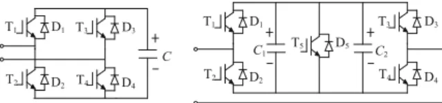
So far, scholars have proposed a variety of sub-module structures with fault clearing capabilities. For example, the well-known full-bridge sub-module [66], and clamped double-sub-module [67], as shown in Fig.8. After the sub-module is blocked, the fault current will flow through the anti-parallel diode to charge the sub-module, and the in-verter outputs a negative voltage to the outside, forcing the fault current to decrease. The schematic diagram of the fault circuit is shown in Fig. 7c. Based on this basic principle, there are multiple sub-modules with the same functions. Such as the tandem-twin module in [68], the enhanced self-resistance submodule in [69], the cross-connected submodule in [70], the hybrid submodules in [71], the diode-clamped submodule in [72], the diode clamped twin module in [73], etc.
Modification of the submodules to be equipped with fault blocking capability usually also brings higher cost and operating loss to the converter [74,75]. After block-ing, the energy of the fault circuit will be used to charge the capacitor of the submodule, which can easily cause the capacitor voltage of the submodule to exceed the voltage limit. Besides, if the reverse EMF provided by the converter is lower than the AC power EMF, it may cause the AC power to feed into the fault point again [76].
Recently, some optimized MMC topologies with fault clearing capabilities have also been proposed. In order to achieve a balance between the DC fault clearing capabil-ities and the economic performance, reference [77] pro-poses a half-bridge submodule and full-bridge submodule cascade hybrid scheme, which can generate reverse EMF without blocking. In reference [78], the branch with current interruption ability is connected across the upper and lower bridge arms of the converter so that the con-verter has the fault current blocking ability.
Compared with the fault clearing scheme based on the AC circuit breaker, the fault clearing scheme based on converter self-clearing has significantly shortened the fault
clearing and recovery time. However, it requires setting the DC side voltage to zero or negative voltage through blocking or modulation, which will affect the normal op-eration of other healthy lines connected by the converter.
6.2 Approach 2: generating a reverse blocking EMF
The fault-clearing scheme based on the DC circuit breaker uses the DC circuit breaker to generate an EMF with the polarity opposite to that of the fault source to clear the fault current. This generated reverse EMF may be connected in series with the fault source or in paral-lel, as seen in Fig.7d and e.
6.2.1 Fault clearing scheme based on DC circuit breakers For DC circuit breakers installed at both ends of the line, the reverse EMF (uinterrupt) is established across the
breaker after receiving the tripping command, as seen in Fig.7d. At the same time, the surge arrester or the non-linear resistance (rinterrupt) in the circuit breaker is
inserted into the fault circuit, which makes the fault current ifaultdrop rapidly. During the fault isolation, the
DC voltage will not drop to zero, so it will not affect the operation of the healthy part of the system. Therefore, this method has been considered as the most promising fault clearing scheme.
At present, three kinds of DC circuit breakers have been proposed: 1) mechanical circuit breakers (MCBs), 2) pure solid-state circuit breakers (SSCBs), 3) hybrid circuit breakers (HCBs) [49, 50]). Among them, the HCB is preferable because of its low on-state loss com-parable to the MCB and its fast-effective fault current interruption capability comparable to the SSCB [79,80]. In 2012, ABB company launched its first hybrid DC cir-cuit breaker, which can breaks DC currents up to 16kA in 2.25 ms [81]. Plenty of industrial and academic re-searches related to the HCB have been carried out since then [82–84]. At present, the HCB has been initially ap-plied in the actual flexible DC project.
Nevertheless, the high cost of the HCB greatly limits its large-scale application. Researchers have made many efforts to reduce the costs of a single HCB in recent years. Fault current limiters [85] and fault current limit-ing strategies [86] were studied to reduce the size and the capacity required for a single HCB. Topologies using fewer and cheaper semiconductors are proposed [87]. Optimized topologies of converters [88] and DC switch yards [58] are also investigated to help to improve the economic performances of the HCB.
block the fault current of the port-n. Based on this idea, reference [89] uses a string of unidirectional series thy-ristor as the selector, and then significantly reduces the costs. In reference [90, 91], a unidirectional bypass branch is used as the selector. However, they cannot interrupt the DC bus fault current. To ensure bidirec-tional current interruption, reference [92] uses a circuit consisting of a bidirectional MB cell in series with a thy-ristor string with anti-parallel diodes as the selector while reference [93–95] uses half the number of MB cells and bidirectional bypass branches [96] as the selec-tors. However, the cost of the multiport HCB in [93,94] is still high, and the breaker in reference [95] is not extendable.
With the expansion of the DC network scale, the cost advantages of employing the multiport HCB will become more obvious. However, the major problem remains to be solved in developing a multiport HCB is to achieve lower costs and higher reliability without losing any current interruption capability. Aiming at this goal, ref-erence [97] proposed a ring-connected multiport HCB, which has the same fault interruption performance as the two-port hybrid DC circuit breaker, whereas the cost is lower than 1/3 of the two-port DC circuit breaker.
Additionally, the reliability of the DC circuit breaker should also be concerned. Due to the complicated struc-ture, the failure rate of existing DC circuit breakers is much higher than that of traditional AC circuit breakers [98]. Among the three types of existing DC circuit brea-kers, the full-solid DC breaker and the hybrid DC circuit breaker with more semiconductor switches have lower reliability than the mechanical DC breaker. In [99], the reliability of the AC distribution networks and DC distri-bution networks were evaluated and compared. The re-sults show that the low reliability of the DC circuit breaker is one of the main reasons for the low reliability of the DC distribution network [98, 100], and it should be further studied.
6.2.2 Fault clearing scheme of the separation converter and line
To coordinate the converter and DC circuit breaker, and reduce the overall cost of the fault clearing equipment,
reference [101,102] proposed a converter and line sepa-rated fault clearing method. The basic idea is to separate the converter and the fault line apart by a bypass branch and then create an energy dissipation branch for the converter and the fault line, respectively. The energy dis-sipation branch can generate parallel reverse EMF both at the outlet of the converter and the line, respectively, so as to reduce the fault current, as shown in Fig.7e.
However, the above fault clearing scheme also needs to redesign the converter, which may affect the perform-ance of the converter. In addition, when the parallel re-verse EMF at the outlet of the converter will also affect the normal operation of other healthy lines.
7 Fault recovery
The development trend of multi-terminal flexible DC systems using overhead lines puts forward higher re-quirements for DC fault isolation. For system recovery after faults in a flexible DC system, CIGRE and many re-search institutions have proposed a variety of solutions, which can be divided into two technical routes [103]: one is based on the protection technology of converters without fault self-clearing ability and DC circuit brea-kers, while the other is based on converters with fault self-clearing ability and an ultrafast disconnector switch (UFD). The former realizes fast isolation, removal and system recovery of faulty lines through the quick trip-ping and closing of DC circuit breakers. In contrast, the latter mainly prevents the continuous discharge of ca-pacitors inside the converter and blocks the short circuit current feed of the AC system by blocking the converter or changing its control mode, and realizes the isolation of faulty lines and restoration of the system through the mechanical switch in the DC lines. In terms of ensuring continuous and reliable transmission of active power in the DC grid, the advantages of adopting the protection technology of converters without fault self-clearing cap-abilities and DC circuit breakers are obvious.
Whether the DC system can restore operation success-fully after a fault mainly depends on the identification of fault properties and the isolation of faulty lines. For tem-porary faults, appropriate recovery methods should be adopted to quickly restore normal operation after the faults are cleared. For permanent faults, the converter should be blocked for line maintenance. At present, re-searches for fault recovery of flexible DC systems can be classified into four categories: fault identification schemes based on AC circuit breakers [104, 105], con-verters [106–111], DC circuit breakers [112–114], and electrical quantities after a fault [115,116].
on communication, which can reduce the system cost. However, this method may interrupt the power of a non-faulty bus during the fault clearing phase, leading to low power supply reliability. What’s more, the perform-ance is poor because the AC circuit breaker operating time is so long that the fault current cannot be inter-rupted in time.
The converter-based recovery strategy is also called re-start strategy. In [106–108], a converter with fault clear-ing capability was operated in a specific mode after fault isolation, then the characteristics of the fault can be judged by DC voltage, DC current and bridge arm current. Reference [109–111] put damping modules in series inside the converter. Through coordinating the mechanical switch, the arm current limiter, the DC cir-cuit breaker and the control of the converter station, the impact of the secondary inrush current can be limited. However, such a fault recovery scheme has limited appli-cations for its converter structure, and when used in a DC power grid, the blocking of the converter valves will disable the whole converter station, expanding the scale of power failure and resulting in low reliability.
A system recovery scheme based on a hybrid DC circuit breaker identifies the fault properties by de-tecting the existence of the fault current bypassing the arrester energy-absorption branch [112–114]. The DC circuit breaker can directly break the fault current through disconnecting the faulty line at high oper-ation speed. Providing the power electronic devices are in their safe operating region, it can ensure the normal operation of non-faulty lines without blocking the converter, solving the problem of DC fault clear-ing and isolation in flexible DC systems and improv-ing system availability. However, there is a problem of blind recovery in the process as the DC circuit breaker automatically recloses after waiting for a fixed deionizing time to restore operation.
The fault property identification scheme based on electrical quantity information recognizes the fault prop-erty by constructing the relationship between the char-acteristic quantity and the fault state. This method largely reflects the inherent mechanism of fault develop-ment. A fault property identification scheme based on the residual voltage characteristic of the faulty pole was proposed in [115]. The fault property recognition was realized by detecting the induced voltage of the healthy pole on the faulty pole after the fault. In [116], charac-teristic signals were injected into healthy lines and the identification of fault property is realized by detecting the coupling characteristic signals of the faulty poles. However, the above-mentioned fault identification methods based on electrical quantities are only applic-able to unipolar short-circuit faults in symmetrical bipo-lar DC systems.
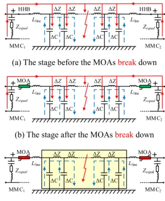
After a DC line fault occurs, according to the operat-ing status of the circuit breaker, the subsequent dis-charge process can be divided into the following three stages:
(1) The stage before MOAs break down.
When the fault has just occurred, the circuit breaker has not yet acted, and the fault current is mainly composed of superposition of the valve-side feed current and the distributed capacitor discharging current, as shown in Fig. 10a, where Zequal represents
the equivalent internal impedance of the MMC and Lline represents the inductance of the current limiting
reactors.
(2) The stage after MOAs break down.
The circuit breaker trips and as the current change rate (di/dt < 0) sharply reverses on the current limiting reactor (Lline), the circuit breaker and the arrester
with-stand a large transient segmented voltage, leading to the arrester being quickly broken down. The discharge cir-cuit is shown in Fig.10b.
(3) The stage after the MOAs restore insulation.
With the release of energy at the valve side, the ar-rester terminal voltage drops rapidly and the insulation is restored. After that, the fault current is mainly the capacitor discharge current distributed to the ground by the line, as shown as Fig.10c.
In fact, during the 100-200 ms after the circuit breaker trips, the distributed capacitance of the DC line to the ground will discharge continuously. This stage contains a large amount of valuable information. If the electrical characteristics quantities representing the moment when the fault disappears can be extracted, it becomes possible to build an adaptive reclosing strategy.
8 Protection technology prospects
In the aspect of DC fault analysis, although scholars have done a lot of research on DC fault development process and the fault characteristics, the influence of the mul-tiple factors such as the converter blocking on the fault transients and the quantitive determination of the fault quantities have not been paid much attention. To complete the researches on DC fault analysis, future studies may focus on the following aspects: 1) fault mechanisms across the whole fault development process still need to be improved and optimized, among which the fault analysis after converter blocking is a significant supplement. 2) Study on the quantitative calculation method of fault time-frequency electric quantities so as to describe the internal and external fault characteristics more accurately and to provide theoretical basis for pro-tection setting.
In terms of protection principle, the exiting protection schemes have their own adaptive scenarios. In the fu-ture, multiple schemes should cooperate to form the pri-mary and backup protection. Voltage and current protection, traveling wave protection, and protection based on boundaries can be used as primary protection because they can ensure the speed of protection; the current differential protection and direction pilot protec-tion can be an important supplement due to the good selectivity and sensibility. The goal is to realize the sci-entific cooperation of main and backup protection. The protection scheme based on the protection-control co-operation can maximize the use of controllable equip-ment such as converters for fault detection, which provides a new direction for the following research.
In terms of DC fault clearing, the scheme based on DC circuit breaker is still the first choice. Several com-panies have developed prototypes of DC circuit breakers that meet the requirements of DC systems, and have been successfully used in actual DC projects. However, the cost and the reliability of the DC circuit breaker may be the main obstacles to its large-scale commercial ap-plication. The future research can be carried out from
two aspects: focusing on reducing the cost of the DC cir-cuit breaker and increasing its reliability.
In terms of fault recovery, the future research should pay more attention to the pre-judgment of fault nature and adaptive reclosing strategy. When the fault is per-manent, HCBs should not reclose to avoid a secondary impact on the system. By analyzing the discharge process of the fault point before and after the trip of HCBs, the viewpoint of identifying the fault nature by using the residual voltage characteristics along the line after HCBs’energy consumption path restores insulation is proposed, which is instructive for the subsequent re-search on adaptive reclosing of flexible DC systems.
9 Conclusion
With many advantages, the flexible DC grid is of great sig-nificance to the development of smart grid. However, the protection and fault handling are the keys to the promotion and application of flexible DC grid. In order to promote fu-ture research of DC grid protection, this paper reviews the recent literatures about fault analysis, protection principle, fault isolation and recovery. Their advantages and disadvan-tages are presented. The development directions of DC grid protection research are recommended:
(1) Analytical expressions of the transient electrical quantities across the whole fault development process can be further investigated.
(2) The combination of various protection schemes constitutes the primary protection, which has the strong immunity to fault resistance and disturbance. And the coordination with backup protection should be further strengthen, realizing the integrity of protection for DC grid.
(3) More attention should be paid to improving the economics and reliability of the existing fault clearing methods.
(4) Fault recovery should focus on identifying the fault nature and detecting the temporary fault
disappearing moment. Making full use of the transient electrical quantity after HCB trips can realize the adaptive reclosing more efficiently.
Abbreviations
LCC:Line commutated converters; VSC: Voltage source converter; MMC: Modular multi-level converter; QCD: Quick-change detection; EMF: (Electromotive Force); MCBs: Mechanical circuit breakers; SSCBs: Solid-state circuit breakers; HCBs: Hybrid circuit breakers; UFD: Ultrafast dis-connector switch
Acknowledgements Not applicable.
Authors’contributions
restore. Jinghan He, Meng Li and Yin Xu reviewed and edited the manuscript. The authors read and approved the final manuscript.
Authors’information
Jinghan He, female, PHD and professor in Beijing Jiaotong University, IEEE Fellow. Her research interests include power system relay protection, monitoring and protection of the railway traction power supply systems. Keao chen, male, PHD student in Beijing Jiaotong University. His research interests include protection and control of VSC-HVDC transmission systems, and HVDC grid.
Meng Li, male, PHD, Postdoc. in Beijing Jiaotong University. His research interest focuses on DC grid protection.
Yiping Luo, female, PHD student in Beijing Jiaotong University. Her research interests include DC grid fault analysis, protection and fault isolation. Chenguang Liang, male, PHD student in Beijing Jiaotong University. His research interests include power system protection and control and flexible dc grid.
Yin Xu, male, PHD and professor in Beijing Jiaotong University. His research interests include power system resilience, distribution system restoration, and power systems electromagnetic transient simulation.
Funding
This work is funded by the Fundamental Research Funds for the Central Universities (No. 2019YJS179).
Availability of data and materials Not applicable.
Competing interests
The authors declare that they have no competing interests.
Received: 7 January 2020 Accepted: 17 April 2020
References
1. Tian, S., Luan, W., Zhang, D., Liang, C., & Sun, Y. (2015). Technical forms and key technologies on energy internet.Proceedings of the CSEE, 35(14), 3482– 3494.
2. Zhou, X., Lu, Z., Liu, Y., & Chen, S. (2014). Development models and key technologies of FutureGrid in China.Proceedings of the CSEE, 34(29), 4999– 5008.
3. Xu, Z., Xue, Y., & Zhang, Z. (2014). VSC-HVDCTechnology suitable for bulk power overhead line transmission.Proceedings of the CSEE, 34(29), 5051– 5062.
4. Tang, G., He, Z., & Pang, H. (2013). Research, application and development of VSC-HVDC Engneering technology.Automation of Electric Power System, 15, 3–14.
5. Marquardt, R. (2012). Stromrichterschaltungen MitVerteilten Energieic ichern. German.
6. Yang, J., Fletcher, J. E., & Reilly, J. O. (2012). Short-circuit and ground fault analyses and location in VSC-based DC network cables.IEEE Transactions on Industrial Electronics, 59(10), 3827–3837.
7. Xu, Z., Xiao, H., Xiao, L., & Zhang, Z. (2018). DC fault analysis and clearance solutions of MMC-HVDC systems.Energies, 11(4), 941–957.
8. Li, B., He, J., Tian, J., Feng, Y., & Dong, Y. (2017). DC fault analysis for modular multilevel converter-based system.Journal of Modern Power Systems and Clean Energy, 5(2), 275–282.
9. Qi, X., Pei, W., Kong, L., Li, L., Xiao, H., & Niu, G. (2019). Analysis on characteristic of DC short-circuit fault in multi-terminal AC/DC hybrid distribution network.The Journal of Engineering, 2019(16), 690–696. 10. Liu, Y., Huang, M., Zha, X., & Iu, H. H. (2019). Short-circuit current estimation
of modular multilevel converter using discrete-time modeling. IEEE Transactions on Power Electronics, 34(1), 40–45.
11. Xu, J., Zhu, S., Li, C., & Zhao, C. (2019). Dc fault current calculation method in MMC-HVDC grid considering current-limiting devices. The Journal of Engineering, 2019(16), 3188–3195.
12. Langwasser, M., Carne, G. D., Liserre, M., & Biskoping, M. (2018). Improved fault current calculation method for pole-to-pole faults in MMC multi-terminal HVDC grids considering control dynamics. In 2018 IEEE energy conversion congress and exposition (ECCE)(pp. 5529–5535).
13. Xu, J., Zhu, S., Li, C., & Zhao, C. (2018). The enhanced DC fault current calculation method of MMC-HVDC grid with fault current limiters. IEEE Journal of Emerging and Selected Topics in Power Electronics, 7(3), 1758–1767. 14. Xu, Y., Yang, H., & Liu, J. (2019). Calculation method of short-circuit current and voltage considering the interaction of different ports in DC system.The Journal of Engineering, 2019(16), 711–714.
15. Yuan, F., Liu, J., Yan, X., Yi, W., & Zhang, X. (2017). A new calculation method for fault transient expression of ring DC systems. In International conference on electrical machines & systems.
16. Li, C., Zhao, C., Xu, J., Ji, Y., Zhang, F., & An, T. (2017). A pole-to-pole short-circuit fault current calculation method for DC grids.IEEE Transactions on Power Apparatus and Systems, 32(6), 4943–4953.
17. Langwasser, M., Carne, G. D., Liserre, M., & Biskoping, M. (2019). Fault current estimation in multi-terminal HVDC grids considering MMC control. IEEE Transactions on Power Apparatus and Systems, 34(3), 2179–2189.
18. Jia, K., Xuan, Z., Chen, J., Feng, T., Zhao, Q., & Bi, T. (2020). Transient switching performance of VSC and the DC fault partitions.International Journal of Electrical Power & Energy Systems, 116, 105503.
19. Cwikowski, O., Wood, A., Miller, A., Barnes, M., & Shuttleworth, R. (2018). Operating DC circuit breakers with MMC. IEEE Transactions on Power Delivery, 33(1), 260–270.
20. Wasserrab, A. (2016).Kurzschlussstromberechnung in Gleichstromnetzen der elektrischen Leistungsübertragung.
21. Wasserrab, A., & Balzer, G. (2015). Determination of DC short-circuit currents of MMC-HVDC converters for DC circuit breaker dimensioning. In 11th IET international conference on AC and DC power transmission(pp. 1–7). 22. Bleilevens, R., & Moser, A. (2018). Algebraic modelling of converters without
DC fault ride-through capability for short circuit current calculation of DC distribution grids. In 2018 53rd international universities power engineering conference (UPEC)(pp. 1–6).
23. Bucher, M. K. (2014). Transient fault currents in HVDC VSC networks during pole-to-ground faults. phd thesis.
24. Bucher, M., & Franck, C. (2016). Analytic approximation of fault current contribution from AC networks to MTDC networks during pole-to-ground faults.IEEE Transactions on Power Delivery, 31(1), 20–27.
25. Xue, S.-M., & Liu, C. (2018). Line-to-line fault analysis and location in a VSC-based low-voltage DC distribution network.Energies, 11(3), 536–552. 26. Saciak, A., Balzer, G., & Hanson, J. (2018). A novel calculation method for
steady-state short-circuit currents in Meshed DC-grids. In 2018 53rd international universities power engineering conference (UPEC) (pp. 1–6). Glasgow: IEEE.
27. Saciak, A., Balzer, G., & Hanson, J. (2019). A calculation method for steady-state short-circuit currents in multi-terminal HVDC-grids. In 15th IET international conference on AC and DC power transmission (ACDC 2019)(pp. 1–6).
28. Pires, C. L., Nabeta, S. I., & Cardoso, J. R. (2008). Second-order model for remote and close-up short-circuit faults currents on DC traction supply.IET Power Electronics, 1(3), 348–355.
29. Bucher, M. K., & Franck, C. M. (2013). Contribution of fault current sources in multiterminal HVDC cable networks. IEEE Transactions on Power Delivery, 28(3), 1796–1803.
30. Wasserrab, A., & Balzer, G. (2014). Frequency-dependent cables for the calculation of line short-circuit currents in HVDC networks. In 2014 49th international universities power engineering conference (UPEC)(pp. 1–6). 31. Ma, Y., Zou, G., Gao, Z., Sun, C., Du, T., & Liu, Y. (2017). Analytic approximation of
fault current contributed by DC capacitors in VSC-HVDC pole-to-pole fault. In 2017 IEEE electrical power and energy conference (EPEC)(pp. 1–6).
32. Bucher, M. K., & Franck, C. M. (2015). Analytic approximation of fault current contributions from capacitive components in HVDC cable networks.IEEE Transactions on Power Delivery, 30(1), 74–81.
33. Yang, S., Xiang, W., & Wen, J. (2019). Review of DC fault protection methods for the MMC based DC grid.Proceedings of the CSEE, 39(22), 6600–6617. 34. Liu, J., Tai, N., & Fan, C. (2017). Transient-voltage-based protection scheme
for DC line faults in the multiterminal VSC-HVDC system.IEEE Transactions on Power Delivery, 32(3), 1483–1494.
35. Li, M., Luo, Y., Jia, K., Bi, T., & Yang, Q. (2020). Frequency-based current differential protection for VSC-MVDC distribution lines.International Journal of Electrical Power & Energy Systems, 117(1), 1–9.
37. Sanaye-Pasand, M., Abedini, M., & Hasani, A. (2014). A traveling-wave-based methodology for wide-area fault location in multi-terminal DC systems.IEEE Transactions on Power Delivery, 29(6), 2552–2560.
38. Jie, Z., Guibin, Z., Xie, Z., et al. (2017). A fastnon-unit line protection strategy for the MMC-based MTDC grid [M]. In 2017 IEEE conference on energy internet and energy system integration (EI2)(pp. 1–6). Beijing: IEEE. 39. Ikhide, M., Tennakoon, S., Griffiths, A., et al. (2015). Fault detection in
multi-terminal modular multilevel converter (MMC) based high voltage DC (HVDC) transmission system [C]. In 2015 50th international universities power engineering conference (UPEC)(pp. 1–6) Stoke on Trent: IEEE.
40. Junjie, Z. H. A. N. G., Weixing, L. I. N., & Jinyu, W. E. N. (2017). DC fault protection based on change rate of DC voltage in DC grid.Southern Power System Technology, 11(1), 14–22.
41. Liang, R., Wang, F., Fu, G., et al. (2016). A general fault location method in complex power grid based on wide-area traveling wave data acquisition. International Journal of Electrical Power & Energy Systems, 83, 213–218. 42. Azizi, S., Sanaye-Pasand, M., Abedini, M., et al. (2014). A traveling-wave-based
methodology for wide-area fault location in multiterminal DC systems.IEEE Transactions on Power Delivery, 29(6), 2552–2560.
43. Azizi, S., Afsharnia, S., & Sanaye-Pasand, M. (2014). Fault location on multi-terminal DC systems using synchronized current measurements. International Journal of Electrical Power & Energy Systems, 63(7), 779–786. 44. Qi, X. M., PEI, W., Li, L. Y., et al. (2018). A fast DC fault detection method for
multi-terminal AC/DC hybrid distribution network based on voltage change rate of DC current-limiting inductor.Energies, 11(7), 1–22.
45. Baran, M. E., & Mahajan, N. R. (2006). Overcurrent protection on voltage-source-converter-based multiterminal DC distribution systems. IEEE Transactions on Power Delivery, 22(1), 406–412.
46. Ying, Z., Nengling, T., & Xu, B. (2012). Fault analysis and traveling-wave protection scheme for bipolar HVDC lines. IEEE Transactions on Power Delivery, 27(3), 1583–1591.
47. Sun, J., Saeedifard, M., & Meliopoulos, A. P. S. (2019). Backup protection of multi-terminal HVDC grids based on quickest change detection. IEEE Transactions on Power Delivery, 34(1), 177–187.
48. Farhadi, M., & Mohammed, O. A. (2015). Event-based protection scheme for a multiterminal hybrid DC power system.IEEE Transactions on Smart Grid, 6(4), 1658–1669.
49. Meghwani, A., Srivastava, S. C., & Chakrabarti, S. A. (2017). Non-unit protection scheme for DC microgrid based on local measurements.IEEE Transactions on Power Delivery, 32(1), 172–181.
50. Rui, L., Xu, L., & Liangzhong, Y. (2017). DC fault detection and location in meshed multiterminal HVDC systems based on DC reactor voltage change rate.IEEE Transactions on Power Delivery, 32(3), 1516–1526.
51. Jian, L., Nengling, T., & Chunju, F. (2017). Transient -voltage-based protection scheme for DC line faults in the multiterminal VSC-HVDC system. IEEE Transactions on Power Delivery, 32(3), 1483–1494.
52. Tzelepis, D., Dysko, A., Fusiek, G., et al. (2017). Single-ended differential protection in MTDC networks using optical sensors.IEEE Transactions on Power Delivery, 32(3), 1605–1615.
53. Bi, T., Wang, S., Jia, K., et al. (2016). Short-term energy-based approach for monopolar grounding line identification in MMC-MTDC system [J].Power System Technology, 40(3), 689–695.
54. Jiawei, H. E., Bin, L. I., Ye, L. I., et al. (2017). A fast-directional pilot protection scheme for the MMC-based MTDC grid.Proceedings of the CSEE, 37(23), 6878–6887 7078.
55. Song, G., Chu, X., Cai, X., et al. (2013). A novel pilot protection principle for VSC-HVDC cable lines based on fault component current. International Journal of Electrical Power & Energy Systems, 53, 426–433.
56. Li, M., Jia, K., Bi, T., Wang, C., Zhu, R., & Yang, Q. (2019). Full-current-based directional pilot protection for VSC-DC distribution systems.IET Generation Transmission and Distribution, 13(16), 3713–3724 208.
57. Jia, K., Zhao, J., et al. (2019). Control and protection coordination based identification strategy of DC fault for photovoltaic DC boosting integration system. In Automation of electric power system.
58. Wang, B., Jia, K. E., Bi, T., Zhao, Q., & Feng, T. (2020). Line protection method for multi-terminal flexible DC distribution system based on control and protection coordination.Proceedings of the CSEE, 40(8), 2559–2569. 59. Song, G., Wang, T., & Hussain, K. S. T. (2019). DC line fault identification
based on pulse injection from hybrid HVDC breaker.IEEE Transactions on Power Delivery, 34(1), 271–280.
60. Wang, S., & Bi, T. (2017). JIA Ke. Single terminal fault location for MMC-HVDC transmission line using active pulse.Transactions of China Electrotechnical Society, 32(1), 12–19.
61. Candelaria, J., & Park, J. (2011). VSC-HVDC system protection: A review of current methods. In 2011 IEEE/PES power systems conference and exposition (pp. 1–7).
62. Tang, L., & Ooi, B. (2007). Locating and isolating DC faults in multi-terminal DC systems.IEEE Transactions on Power Delivery, 22(3), 1877–1884. 63. Guanjun, D., Guangfu, T., Zhiyuan, H., & Ming, D. (2008). New technologies
of voltage source converter (VSC) for HVDC transmission system based on VSC. In 2008 IEEE power and energy Society general meeting - conversion and delivery of electrical energy in the 21st century(pp. 1–8).
64. Li, X., Song, Q., Liu, W., Rao, H., Xu, S., & Li, L. (2013). Protection of nonpermanent faults on DC overhead lines in MMC-based HVDC systems. IEEE Transactions on Power Delivery, 28(1), 483–490.
65. Elserougi, A. A., Abdel-Khalik, A. S., Massoud, A. M., & Ahmed, S. (2014). A new protection scheme for HVDC converters against DC-side faults with current suppression capability.IEEE Transactions on Power Delivery, 29(4), 1569–1577.
66. Marquardt, R. (2011). Modular multilevel converter topologies with DC-short circuit current limitation. In In 8th International Conference on Power Electronics - ECCE Asia(pp. 1425–1431).
67. Hu, J., Zeng, R., & He, Z. (2016). DC fault ride-through of MMCs for HVDC systems: A review.The Journal of Engineering, 2016(9), 321–331.
68. Jianpo, Z., Chengyong, Z., & Haifeng, S. U. N. (2014). Improved topology of modular multilevel converter and application. Transactions of China Electrotechnical Society, 29(8), 173–179.
69. Xiang, W., Lin, W., Wen, J., Yao, L., & Zhibing, W. (2016). Equivalent electromagnetic model of self-blocking MMC with DC fault isolation capability. In 2016 IEEE power and energy Society general meeting (PESGM) (pp. 1–5).
70. Nami, A., Wang, L., Dijkhuizen, F., & Shukla, A. (2013). Five level cross connected cell for cascaded converters. In 2013 15th European conference on power electronics and applications (EPE)(pp. 1–9).
71. Zeng, R., Xu, L., & Yao, L. (2014). An improved modular multilevel converter with DC fault blocking capability. In 2014 IEEE PES general meeting | Conference & Exposition(pp. 1–5).
72. Li, X., Liu, W., Song, Q., Rao, H., & Xu, S. An enhanced MMC topology with DC fault ride-through capability(pp. 6182–6188). Vienna: IEEE.
73. Xiaoqian, L., Wenhua, L., Qiang, S., Hong, R., Zhe, Z., & Xiaolin, L. (2014). An enhanced MMC topology with DC fault clearance capability.Proceedings of the CSEE, 34(36), 6389–6397.
74. Wu, J., Yao, L., Wang, Z., Li, Y., Yang, B., & Y. J. P. o. t. C. CAO. (2015). The study of MMC topologies and their DC fault current blocking capacities in DC grid.Proceedings of the CSEE, 35(11), 2681–2694.
75. Guoqing, L. I., Zhenzi, S., & Guoyou, W. (2019). Asymmetric full bridge sub-module topology of MMC with DC fault blocking capability.High Voltage Engineering, 45(1), 12–20.
76. Bin, L. I., Ye, L. I., & Jiawei, H. E. (2016). Research on the key properties of MMC sub-modules with DC fault eliminating capability.Proceedings of the CSEE, 36(8), 2114–2122.
77. Adam, G. P., Ahmed, K. H., & Williams, B. W. Mixed cells modular multilevel converter(pp. 1390–1395). Istanbul: IEEE.
78. Li, S., et al. (2019). An auxiliary DC circuit breaker Utilising an augmented MMC. In IEEE Transactions on power delivery(p. 1).
79. Franck, C. M. (2011). HVDC circuit breakers: A review identifying future research needs.IEEE Transactions on Power Delivery, 26(2), 998–1007. 80. Shukla, A., & Demetriades, G. D. (2015). A survey on hybrid circuit-breaker
topologies.IEEE Transactions on Power Delivery, 30(2), 627–641.
81. Liu, J., Tai, N., Fan, C., & Chen, S. (2017). A hybrid current-limiting circuit for DC line fault in multi-terminal VSC-HVDC system. IEEE Transactions on Industrial Electronics, 64(7), 5595–5607.
82. Peng, C., Husain, I., Huang, A. Q., Lequesne, B., & Briggs, R. (2016). A fast-mechanical switch for medium-voltage hybrid DC and AC circuit breakers. IEEE Transactions on Industry Applications, 52(4), 2911–2918.
83. Wen, W., Huang, Y., Sun, Y., Wu, J., Al-Dweikat, M., & Liu, W. (2016). Research on current commutation measures for hybrid DC circuit breakers. IEEE Transactions on Power Delivery, 31(4), 1456–1463.