TECHNICAL UNIVERSITY OF CLUJ-NAPOCA
ACTA TECHNICA NAPOCENSIS
Series: Applied Mathematics, Mechanics, and Engineering Vol. 61, Issue IV, November, 2018
TOOL MACHINERY FRAMES COMPARISON: WELDED OR MOLDED
STRUCTURES
Dan Ovidiu GLAVAN, Nicolae URSU-FISCHER, Theoharis BABANATSAS, Ioan RADU, Roxana Mihaela BABANATIS-MERCE
Abstract: Precision of manufactured object is the main goal for all engineers in modern times. The times of massive structures with high weight and displacement have passed. We are developing now our research in order to define new type of structures with controlled deformations with values easy to predict and therefore to correct with the clear purpose to get the „ideal” manufactured product. The paper is analyzing welded and molded structures willing to determine advantages and disadvantages of using them for frames in projecting, producing and exploitation of tool machinery.
Key words: Structures, static load, dynamic load, precision, manufacturing, welded, molded, vibrations.
1. INTRODUCTION
The classic idea about increasing the rigidity of the structure with the purpose to obtain higher precision in the process of manufacturing is to over dimension the structure obtaining as a result minimum deformations and low amplitude vibrations. Having harder structure has as a consequence the increase of the quantity of the material used to build the structure, increase of total weight and significant higher costs. In the modern industrial era this point of view is not accepted anymore due especially to the great achievements that the computer zone and artificial intelligence have suffered.
Our alternative is taking in consideration that it is not anymore inconvenient the fact the bedframe is changing itself as dimension and basic shape due to the stress produced by the forces and moments that are acting in the manufacturing process, with the basic restriction that the information about the behavior of the structure is transmitted to us in real time (by real time understanding the time interval short enough between the process of deformation took part and the final movement of the cutting tool that ensures the right
precision to the manufactured surface) and allows corrective actions in idea to compensate the displacements of the structure giving as final result the desired precision of manufacturing.
2. ABOUT THE PROBLEM
Reaching the maximum manufacturing precision means almost zero errors in dimensions and shape and it is strictly related to the fact that the command system of the tool machinery has to get in real time the information about the values of the displacement in the cross section of the structure when the cutting tool is acting,
information unavailable by direct
What is the true value of deformation is the cross section of the bedframe where the cutting tool is acting and how can be this value determined is our main issue that we are trying to offer an answer for. Solving the problem is not possible using material resistance classic methods, so we need to make use of innovative thinking with multiple non-determined variables put all together in one system of equations that can reply mathematically the real process.
An example for applying the classic methods for the turning machine are presented in figure 1.
Fig. 1. Classic methods for calculating forces
For this, particular, example, we can use the classic equations of equilibrium, along the three axes of the triple orthogonal reference system, for forces and for the torques three equations of equilibrium around the axes. Those six
equations resulting are completely
nonsufficient, the number of un-known parameters being in total at least eight so the double undetermined system must be solved [2], [3], [4], [5].
3. CLASIC SOLUTION
The value of the cutting forces is resulting from the technological process, the reaction forces and the friction forces we will calculate them in the right position of the pressure center and finally we can deduct the equations.
In this point it becomes very clear that the six-equation system available with double
indetermination can’t offer us the values for eight unknown parameters. The only solution is that we will use two complementary equations. With old well-known methods of resistance material, it’s almost impossible to determinate those two equations. We will try to get the compulsory two equations out from a particular shape of the structure and from the manufacturing process characteristics fact that leads us to the final results.
3.1 Improving the classic solution
Improving the classic solutions in this point it is very clear that we can’t write any supplementary equations with the probability of 100 % being sure but we only can add a few equations coming from the real conditions in the manufacturing process fact that conduct the solution to a probability to be sure. In fact, if we are adding two of those equations we will need a third one to use it in order to confirm or not our expectances (equations coming from manufacturing process experience) [6], [7], [8], [8].
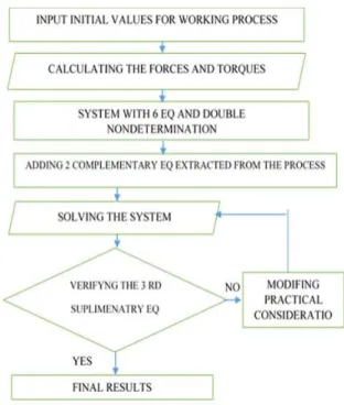
The whole process can be described now like an algorithm in conclusion we can determine a logic process that is happenning as in figure 2.
The problem is solved in this point only if the third equation fulfills the conditions of the other two, if not we must initiate the process again, changing a little bit the first two equations and repeating the procedure (the classic procedure of successive iterations).
4. NEW MWTHODS
Results can be obtained or not using this logic but not in real time, everything depending on the inspiration of choosing the supplementary equations, real time meaning fast enough to establish a value that can generate the compensation movement of the tool [3], [7], [10].
The finite element method, stays the last chance to close the problem but to use it is another discussion, the method being fitted to calculate structures that are let say more “static”, or in our situation we need almost instantly calculation and then instantly feedback reaction for corrective measures from the machine, things that are not possible basic because of two problems:
1. The method requires a complex enough software (with complete algorithms) and a very strong computer being able to apply the method in real time (time enough for the machine to take the result and make the correction);
2. The mechanical systems on the machine are not fast enough to do the correction in real time, most of them, classic used, being too slow.
Fig. 3. Finite element method
For example, for the structure mentioned above the finite element method will show in figure 3 [11], [12].
Finite element method It is impossible to run a software with the finite element method in real time, and wishing to obtain some advantages from the excellent precision that the finite element method is offering results being shown in Figure 4 [11], [13], [14].
Fig. 4. Finite element method
The steps needed to fulfill to solve the problem and to get the accurate value of displacement are:
A.Modelling the real bedframe with the use of the elements available in the library of the finite element software;
B. Calculating the stress interval that is acting on the structure taking in consideration the process parameters;
C. Choosing a convenient increment, we can use the meth-od step by step covering the whole interval;
D. The results (deformations) will be organized in a data base;
system of adaptive force control device of the machine;
F. In order to speed up the process, it will use not the function of force that is resulting from the device like output but the first or better the second derivate the controlled function that offers us a predictability of the evolution for the force, with evident gain in time to control the parameters of the process;
G. The information that we own in this point permit us to go now to the data base of deformation and make an interpolation of the values of forces we can approximate acceptably the deformation;
H. Having deformation calculated, we can order an almost instant reaction to the machine that will compensate the deformation using new developed sources of movement (engines) like the magneto strictive engine with almost instant reaction as main advantage.
Using this procedure, we can also improve the structure it-self [4], [5].
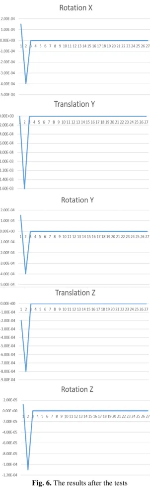
If in the beginning the deformations of the structure were as shown in figure 5.
5. CONCLUSION
After we are following all steps, we are analyzing the results and then we must modify the structure in order to react better we have obtained
Fig. 6. The results after the tests
In each situation, due to its particularity, both classic or modern methods, can be applied,
the results being very much influenced by the inspiration of the engineer that has to extract
mathematic information from the
manufacturing process particularity.
8. REFERENCES
[1]Glavan, D.O., Babanatsas, Th.,Borzan, M., Radu, I., Babanatis Merce, R.M..
Considerations about command system for lathes with numerical controls, adaptive controls and copying system with hydraulic modules or computer assisted, The 10th International Symposium Machine and
Industrial Design in Mechanical
Engineering, 6–8 June, Novi Sad, Serbia, 2018
[2] Korka, Z.I.. Maşini unelte : construcţie şi cinematică, Ed. Eftimie Murgu, 2014, 254 pp., ISBN 978-606-631-042-0
[3] Glavan, D.O., Babanatsas, Th.. Tool machinery vibrations frames comparison
concerning welded or moulded
manufacturing structures, 8th International Conference on Manufacturing Science and Education - Trends in new industrial revolution, 7-9 June, Sibiu, Romania, 2017 [4] Kiss, I., Alexa, V., Cioata, V. G.. Statistical
analysis using the multiple regression research in areas of the indefinite chilled
cast-iron rolls manufacturing, Conference
on Innovative Ideas in Science, 10-11 Nov, Baia Mare, Romania, 2016
[5] Glavan, D.O., Babanatsas, T., Babanatis Merce, R.M., Glavan, A.. Comparative study
of tool machinery sliding systems;
Comparison between plane and cylindrical
basic shapes, International Conference on
Applied Sciences, 10–12 May, Hunedoara, Romania, 2017
[6]
http://www.schrauben-jaeger.de/tradepro/shop/artikel/docs/DIN981 .pdf, 19.06.2018, 18.27.
[7] http://www.stamel.ro/files/produse/fise-tehnice/1277816133_din39.pdf, 19.06.2018, 21.25.
[8] DRĂGHICI, I., Îndrumar de proiectare în
construcția de mașini vol.1 Ed. Tehnică
[9] Pop, D., Haragâş, S:. Organe de maşini.
Volumul 1, Ed. Risoprint, Cluj-Napoca, 2014, 352 pp., ISBN 978-973-53-1294-7 [10] Guestoriu, I. R., Tucu, D.. Stress risk in
management systems in metallurgical problems, 22nd International Conference on Metallurgy and Materials (METAL), 15-17 May, Brno, Czech Republic, 2013
[11] Radu, I.. Mecanica - vol. II Cinematica,
Ed. Mirton Timisoara, 2001, 157 pp., ISBN
973-0-00331-9
[12] Radu I., Glăvan, D.. Elemente de vibraţii
mecanice, Ed. „UAV” Arad, 2001, 127 pp., ISBN 973-9361-50-1
[13] Sima, Gh.. Sisteme senzoriale utilizate la sudare, Ed. „ Viata Arădeana“ Arad, 2004,
172 pp., ISBN 973-9455-56-9
[14] Mortoiu, D., Săbăilă, L., Babanatsas, Th.,
Gal L.. Autocad 2006, partea I– modelarea 2d, Îndrumător pentu uzul studenţilor, Ed. Universităţii “Aurel Vlaicu”, Arad, 2006,
160 pp., ISBN (10) 973 – 752-092-0
Comparația ghidajelor mașinilor unelte: structurile sudate sau turnate
Rezumat: În această lucrare este studiată problema preciziei obiectului fabricat care este obiectivul
principal pentru toți inginerii. Astăzi nu se mai folosesc structuri masive cu deformații reduse. În
cercetarea noastră am dezvoltat noi tipuri de structuri cu deformări controlate, ușor de prezis
astfel cu anumite corectări să putem obține produsul "ideal". În lucrarea asta analizăm structurile
sudate și turnate determinând, astfel, avantajele și dezavantajele utilizării lor pentru ghidaje, în
proiectarea, producerea și exploatarea mașinilor de unelte.
Dan Ovidiu GLAVAN, Conf. dr. eng., “Aurel Vlaicu” University Arad, Faculty of Engineering,
Department of Automation, Industrial engineering, Textile production and Transport, E-mail: [email protected], Phone: 0257-283010
Nicolae URSU-FISCHER, Prof. dr. eng. math., Technical University of Cluj-Napoca, Department
of Mechanical Systems Engineering, E-mail: [email protected], Phone: 0264-401659
Theoharis BABANATSAS, As. Drd. eng., “Aurel Vlaicu” University Arad, Faculty of
Engineering, Department of Automation, Industrial engineering, Textile production and Transport, E-mail: [email protected], Phone: 0257-283010
Ioan RADU, Prof. dr. eng., “Aurel Vlaicu” University Arad, Faculty of Engineering, Department of
Automation, Industrial engineering, Textile production and Transport, E-mail: [email protected], Phone: 0257-283010
Roxana Mihaela BABANATIS-MERCE, As. Drd. eng., “Aurel Vlaicu” University Arad, Faculty