Micros oft® E xchange 2010 on VMware®
Best Practices Guide
Best Practices Guide
© 2010 VMware, Inc. All rights reserved. This product is protected by U.S. and international copyright and intellectual property laws. This product is covered by one or more patents listed at
VMware, VMware vSphere, VMware vCenter, the VMware “boxes” logo and design, Virtual SMP and VMotion are registered trademarks or trademarks of VMware, Inc. in the United States and/or other jurisdictions. All other marks and names mentioned herein may be trademarks of their respective companies.
Best Practices Guide
Contents
1.
Introduction ... 5
1.1 Overview ... 5
1.2 Purpose ... 5
1.3 Target Audience ... 5
1.4 Scope ... 6
2.
ESX Host Best Practices for Exchange ... 7
2.1 CPU Configuration Guidelines ... 7
2.2 Memory Configuration Guidelines... 8
2.3 Storage Virtualization ... 10
2.4 Networking Configuration Guidelines ... 15
3.
Exchange Performance on vSphere ... 18
3.1 Overview ... 18
3.2 Key Performance Considerations ... 19
3.3 Performance Testing ... 19
3.4 Ongoing Performance Monitoring and Tuning ... 20
3.5 vSphere Performance Features and Exchange ... 21
4.
Exchange 2010 Capacity Planning ... 22
4.1 Capacity Planning Process Overview ... 22
4.2 Mailbox Server: Planning for CPU ... 23
4.3 Mailbox Server: Planning for Memory ... 26
4.4 Mailbox Server: Planning for Storage ... 28
4.5 Hub Transport and Client Access Server Planning ... 29
4.6 Scaling Exchange for the Enterprise... 31
4.7 vSphere Limitations ... 33
5.
Sizing Examples ... 34
5.1 Standalone Mailbox Server – 16,000 Users (150 sent/received) ... 34
Best Practices Guide
6.
vSphere Enhancements for Deployment and Operations ... 64
6.1 VMware VMotion, VMware DRS, and VMware HA ... 64
6.2 Templates ... 65
6.3 VMware vCenter Lab Manager ... 65
6.4 VMware vCenter AppSpeed ... 66
6.5 VMware vCenter Site Recovery Manager ... 67
Best Practices Guide
1. Introduction
1.1 Overview
E-mail has become one of the most critical applications in an organization’s IT infrastructure.
Organizations increasingly rely on messaging tools for individual and organizational effectiveness. As a result, messaging administrators face a constant challenge as they continually seek to manage the conflicting demands of availability, agility, and cost.
Microsoft® Exchange is the most widely used email system in the world. Its operational and performance characteristics are well understood, and best practices for design, deployment, and operations are readily accessible. Exchange continues to evolve through enhanced features and functionality, and through previous limitations addressed with each successive new version.
With its release of Exchange Server 2010, Microsoft has added many features that improve messaging performance, reliability, and scalability. These provide a major step forward. However, Exchange Server 2010 is still subject to many of the shortcomings inherent in most applications running directly on physical hardware, such as hardware platform dependence, under-utilization of server computing resources, lack of flexibility to respond to changing workloads, and heavy costs associated with maintaining disaster recovery, test, and development environments. The architectural improvements in Exchange Server 2010 cannot fully address these limitations.
The ideal platform for Exchange would adapt easily to changing workloads, provide flexibility to accommodate changing demands on an organization’s IT infrastructure, remain reliable and resilient despite system outages, and improve both staff and infrastructure hardware effectiveness. A new operational platform based on VMware vSphere™ can accomplish these goals.
1.2 Purpose
This guide provides best practice guidelines for deploying Exchange Server 2010 on vSphere. The recommendations in this guide are not specific to any particular set of hardware or to the size and scope of any particular Exchange implementation. The examples and considerations in this document provide guidance only and do not represent strict design requirements, as the flexibility of Exchange Server 2010 on vSphere allows for a wide variety of valid configurations.
1.3 Target Audience
This guide assumes a basic knowledge and understanding of vSphere and Exchange Server 2010. • Architectural staff can reference this document to gain an understanding of how the system will work
as a whole as they design and implement various components.
• Engineers and administrators can use this document as a catalog of technical capabilities.
• Messaging staff can reference this document to gain an understanding of how Exchange might fit into a virtual infrastructure.
Best Practices Guide
1.4 Scope
The scope of this document is limited to the following topics:
• ESX Host Best Practices for Exchange – This section provides best practice guidelines for properly preparing the vSphere platform for running Exchange Server 2010. This section includes guidance in the areas of CPU, memory, storage, and networking.
• Exchange Performance on vSphere – This section provides background information on Exchange Server 2010 performance in a virtual machine. It also provides information on official VMware partner testing and guidelines for conducting and measuring internal performance tests.
• Exchange 2010 Capacity Planning – Sizing Exchange 2010 to run in a virtual machine follows many of the same best practices as sizing on physical servers; however, with the introduction of new Exchange 2010 features (i.e., Database Availability Groups), the Capacity Planning process has changed significantly. This section walks through this new process.
• Sizing Examples – In this section, we apply the new Capacity Planning process to two sample configurations, one with Database Availability Groups and one without.
• vSphere Enhancements for Deployment and Operations – This section provides a brief look at vSphere features and add-ons that enhance deployment and management of Exchange 2010. The following topics are out of scope for this document, but may be addressed in other documentation in this Solution Kit:
• Design and Sizing Examples – This information can be found in the Microsoft Exchange 2010 on VMware: Design and Sizing Examples
• Availability and Recovery Options – Although this document briefly covers VMware features that can enhance availability and recovery, a more in-depth discussion of this subject is covered in the
document included in this Solution Kit, which expands upon the examples in this guide by showing how the Capacity Planning process works for small, medium, and enterprise configurations.
Microsoft Exchange 2010 on VMware: Availability and Recovery Options
It is important to note that this and other guides in this Solution Kit are limited in focus to deploying Exchange on vSphere. Exchange deployments cover a wide subject area, and Exchange-specific design principles should
included in this Solution Kit.
Best Practices Guide
2. ESX Host Best Practices for Exchange
A solidly designed ESX host platform is crucial to the successful implementation of enterprise applications such as Exchange. Before we address best practices specific to the Exchange application, the following sections outline general best practices for designing vSphere.
2.1 CPU Configuration Guidelines
2.1.1 Physical and Virtual CPUs
VMware uses the terms virtual CPU (vCPU) and physical CPU to distinguish between the processors within the virtual machine and the underlying physical x86/x64-based processor cores. Virtual machines with more than one virtual CPU are also called SMP (symmetric multi-processing) virtual machines. The virtual machine monitor (VMM) is responsible for virtualizing the CPUs. When a virtual machine starts running, control transfers to the VMM, which is responsible for virtualizing guest OS instructions.
2.1.2 Virtual SMP
VMware Virtual Symmetric Multi-Processing (Virtual SMP) enhances virtual machine performance by enabling a single virtual machine to use multiple physical processor cores simultaneously. vSphere supports use of up to eight virtual CPUs per virtual machine. The biggest advantage of an SMP system is the ability to use multiple processors to execute multiple tasks concurrently, thereby increasing
throughput (for example, the number of transactions per second). Only workloads that support
parallelization (including multiple processes or multiple threads that can run in parallel) can really benefit from SMP.
The virtual processors from SMP-enabled virtual machines are co-scheduled. That is, if physical processor cores are available, the virtual processors are mapped one-to-one onto physical processors and are then run simultaneously. In other words, if one vCPU in the virtual machine is running, a second vCPU is co-scheduled so that they execute nearly synchronously. The following points should be considered when using multiple vCPUs:
• Simplistically, if multiple, idle physical CPUs are not available when the virtual machine wants to run, the virtual machine will remain in a special wait state. The time a virtual machine spends in this wait state is called ready time
• Even idle processors perform a limited amount of work in an operating system. In addition to this minimal amount, the ESX host manages these “idle” processors, resulting in some additional work by the hypervisor. These low-utilization vCPUs compete with other vCPUs for system resources.
.
In VMware ESX™ 4, the CPU scheduler has undergone several improvements to provide better
performance and scalability; for details, see the paper
scheduling constraints due to co-scheduling requirements are further reduced. These improvements have resulted in better linear scalability and performance of Exchange workloads, as described in the
“Exchange Performance on vSphere” section of this document, while reducing inefficiencies introduced by idle vSMP virtual machines. Consequently, in vSphere, the larger 4-way and 8-way virtual machines
Best Practices Guide Consequently, VMware recommends the following practices:
• Only allocate multiple vCPUs to a virtual machine if the anticipated Exchange workload can truly take advantage of all the vCPUs.
• If the exact workload is not known, size the virtual machine with a smaller number of vCPUs initially and increase the number later if necessary.
• For performance-critical Exchange virtual machines (i.e., production systems), try to ensure the total number of vCPUs assigned to all the virtual machines is equal to or less than the total number of cores on the ESX host machine.
While larger virtual machines are possible in vSphere, VMware recommends reducing the number of virtual CPUs if monitoring of the actual workload shows that the Exchange application is not benefitting from the increased virtual CPUs. For more background, please see the “ESX CPU Considerations”
section in the white paper
Setting a CPU Reservation sets a guaranteed CPU allocation for the virtual machine. This practice is generally not recommended because the reserved resources are not available to other virtual machines and flexibility is often required to manage changing workloads. However, SLAs and multi-tenancy may require a guaranteed amount of compute resource to be available. In these cases, reservations ensure these requirements are met. VMware has conducted tests on virtual CPU over-commitment with SAP and SQL, showing that the performance degradation inside the virtual machines is linearly reciprocal to the over-commitment. As the performance degradation is “graceful,” any virtual CPU over-commitment can be effectively managed by using VMware DRS and VMware VMotion™ to move virtual machines to other ESX hosts to obtain more processing power.
2.1.3 Hyper-threading
Hyper-threading technology (recent versions of which are called symmetric multithreading, or SMT) allows a single physical processor core to behave like two logical processors, essentially allowing two independent threads to run simultaneously. Unlike having twice as many processor cores—which can roughly double performance—hyper-threading can provide anywhere from a slight to a significant increase in system performance by keeping the processor pipeline busier. For example, an ESX host system enabled for SMT on an 8-core server will see 16 threads that appear as 16 logical processors.
2.2 Memory Configuration Guidelines
This section provides guidelines for allocation of memory to Exchange virtual machines. The guidelines outlined here take into account vSphere memory overhead and the virtual machine memory settings.
2.2.1 ESX Memory Management Concepts
vSphere virtualizes guest physical memory by adding an extra level of address translation. Shadow page tables make it possible to provide this additional translation with little or no overhead. Managing memory in the hypervisor enables the following:
• Memory sharing across virtual machines that have similar data (i.e., same guest operating systems) • Memory over-commitment, which means allocating more memory to virtual machines than is
Best Practices Guide
2.2.2 Virtual Machine Memory Concepts
Figure 1 illustrates the use of memory settings parameters in the virtual machine.
Figure 1. Virtual Machine Memory Settings
The vSphere memory settings for a virtual machine include the following parameters: • Configured memory = memory size of virtual machine assigned at creation.
• Touched memory = memory actually used by the virtual machine. vSphere only allocates guest operating system memory on demand.
• Swappable = virtual machine memory that can be reclaimed by the balloon driver or by vSphere swapping. Ballooning occurs before vSphere swapping. If this memory is in use by the virtual machine (i.e., touched and in use), the balloon driver will cause the guest operating system to swap. Also, this value is the size of the per-virtual machine swap file that is created on the VMware Virtual Machine File System (VMFS) file system (“.vswp” file).
• If the balloon driver is unable to reclaim memory quickly enough, or is disabled or not installed, vSphere forcibly reclaims memory from the virtual machine using the VMkernel swap file
2.2.3 Allocating Memory to Exchange Virtual Machines
.
Microsoft has developed a thorough sizing methodology for Exchange server that has matured over the last couple of versions of Exchange. VMware recommends using the memory sizing guidelines set by Microsoft. This methodology is discussed in detail in section 4.2 of this guide. Simplistically the amount of memory required for an Exchange server is driven by its role and, if it is a mailbox server, the number of mailboxes on that server. From the perspective of VMware specifics the architect should consider the VMM memory requirements on top of the memory requirements for the Exchange server itself. As Exchange servers are memory intensive and performance is often a key factor (e.g., in production environments), VMware recommends the following practices:
• Do not over-commit memory on ESX hosts running Exchange workloads. For production systems, it is possible to enforce this policy by setting the memory reservation to the configured size of the virtual machine. Also note that:
o Setting memory reservations may limit VMware VMotion™. A virtual machine can only be migrated if the target ESX host has free physical memory equal to or greater than the size of the reservation.
o Setting the memory reservation to the configured size of the virtual machine results in a per-virtual machine vmkernel swap file of zero bytes that will consume less storage and help increase
Best Practices Guide • Enable DRS to balance workloads in the ESX cluster. DRS and reservations can guarantee critical
workloads have the resources they require to operate optimally.
• To minimize guest operating system (OS) swapping, the configured memory size of the virtual machine should be greater than the average memory usage of Exchange running in the guest OS. If the Exchange virtual machine needs more memory than has been allocated, the guest OS
paging/swapping mechanisms are invoked as in normal, native operations. Memory and swap/page file configuration for Exchange virtual machines follow the same guidelines as for native
environments. In general, these should be set to minimize any guest OS swapping.
2.2.4 Advanced Memory Management
The guidelines described above are purposely conservative to avoid kernel swapping between ESX and the guest OS—important due to the mission-critical nature of Exchange, which must often meet stringent SLAs, and the memory intensive nature of the application. This best practice can also apply to non-production systems with high performance SLAs for developers and testers who support non-production environments.
However, it is feasible that once the Exchange workload is known and predictable, if VMware vCenter™ reports that steady state active memory usage is below the amount of memory on the ESX host, then the reservation settings may be relaxed to the steady state active memory value. This scenario is discussed
in the VMworld® 2009 presentation, TA2627 –
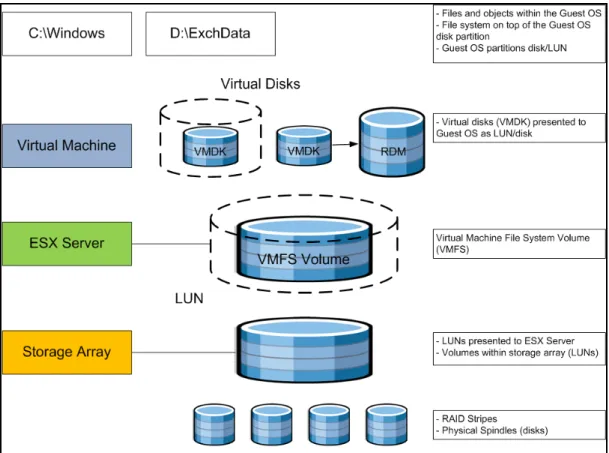
2.3 Storage Virtualization
VMFS is a cluster file system that provides storage virtualization optimized for virtual machines. Each virtual machine is encapsulated in a small set of files and VMFS is the default storage system for these files on physical SCSI disks and partitions. VMware supports Fibre-Channel, iSCSI, and NAS shared-storage protocols.
It is preferable to deploy virtual machine files on shared storage to take advantage of VMware VMotion, VMware High Availability (HA), and VMware Distributed Resource Scheduler (DRS). This is considered a best practice for mission-critical Exchange deployments, which are often installed on third-party, shared-storage management solutions.
VMware storage virtualization can be categorized into three layers of storage technology, as illustrated in Figure 2. The storage array is the bottom layer, consisting of physical disks presented as logical disks (storage array volumes or LUNs) to the layer above, with the virtual environment occupied by vSphere. Storage array LUNs that are formatted as VMFS volumes in which virtual disks can be created. Virtual machines consist of virtual disks that are presented to the guest operating system as disks that can be partitioned and used in file systems.
Best Practices Guide
Figure 2. VMware Storage Virtualization Stack
2.3.1 Storage Multipathing
VMware recommends you set up a minimum of four paths from an ESX host to a storage array, which means the host requires at least two HBA ports.
Best Practices Guide The terms used in Figure 3 are:
• HBA (Host Bus Adapter) – A device that connects one or more peripheral units to a computer and manages data storage and I/O processing.
• FC (Fibre Channel) – A gigabit-speed networking technology used to build storage area networks (SANs) and to transmit data.
• SP (Storage Processor) – A SAN component that processes HBA requests routed through an FC switch and handles the RAID/volume functionality of the disk array.
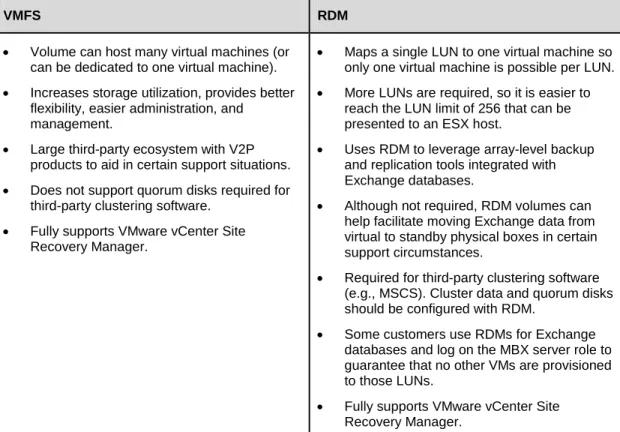
2.3.2 Raw Device Mapping
VMFS also supports Raw Device Mapping (RDM). RDM allows a virtual machine to directly access a volume on the physical storage subsystem, and can only be used with Fibre Channel or iSCSI. RDM can be thought of as providing a symbolic link from a VMFS volume to a raw volume. The mapping makes volumes appear as files in a VMFS volume. The mapping file, not the raw volume, is referenced in the virtual machine configuration.
There are no concrete recommendations for using VMFS or RDM in Exchange deployments, although the following table summarizes some of the options and trade-offs. For a more complete discussion, please
consult t
Table 1. VMFS and Raw Disk Mapping Trade-offs
VMFS RDM
• Volume can host many virtual machines (or can be dedicated to one virtual machine). • Increases storage utilization, provides better
flexibility, easier administration, and management.
• Large third-party ecosystem with V2P products to aid in certain support situations. • Does not support quorum disks required for
third-party clustering software. • Fully supports VMware vCenter Site
Recovery Manager.
• Maps a single LUN to one virtual machine so only one virtual machine is possible per LUN. • More LUNs are required, so it is easier to
reach the LUN limit of 256 that can be presented to an ESX host.
• Uses RDM to leverage array-level backup and replication tools integrated with Exchange databases.
• Although not required, RDM volumes can help facilitate moving Exchange data from virtual to standby physical boxes in certain support circumstances.
• Required for third-party clustering software (e.g., MSCS). Cluster data and quorum disks should be configured with RDM.
• Some customers use RDMs for Exchange databases and log on the MBX server role to guarantee that no other VMs are provisioned to those LUNs.
Best Practices Guide It is also possible and even advantageous in some circumstances to mix VMFS and RDM in Exchange environments under the following conditions:
• Where existing systems already make use of third-party storage management software, RDM can be used to leverage practices based on these products such as storage-based backups to disk.
• RDM is required when using third-party clustering software.
• RDM is useful for enabling the database portability feature of the Exchange database. Running the database on an RDM volume gives an administrator the option of pointing both virtual machines and physical servers to the same storage. This can be particularly useful in support situations that require problems be reproduced on a physical server.
• Deploying multiple, non-production Exchange systems on VMFS facilitates easier management and administration of template cloning, snapshots, and storage consolidation.
• A mixed storage configuration is viable for an Exchange virtual machine. The guest OS is installed on VMFS and the Exchange database and log files on RDM. VMware template cloning can be used for the guest OS and database files can be managed by third-party storage management software. • Database datafiles should be spread out over multiple LUNs, similar to those in native setups,
following the storage vendor or ISV guidelines for database layout, LUN and spindle configuration. • Maintain a 1:1 mapping between the number of virtual machines and LUNs to avoid any disk I/O
contention.
• A minimum of two HBA adaptors should be configured per ESX host.
• Follow the guidelines in the “Hardware Storage Considerations” and “Guest Operating Systems” sections of Performance Best Practices for VMware vSphere 4.
It is important to note that there are several different shared-storage options available to ESX (iSCSI, Fibre Channel, NAS, etc.); however, Microsoft does not currently support NFS for the Mailbox Server role (clustered or standalone). For Mailbox servers that belong to a Database Availability Group, only Fibre Channel is currently supported; iSCSI can be used for standalone mailbox servers. To see the most recent list of compatibilities please consult the latest
Best Practices Guide
2.3.3 Number of Virtual Machines per LUN
The number of virtual machines allocated to a VMFS LUN influences the final architecture. Figure 4 illustrates the concepts and highlights the differences between a one-to-one and many-to-one virtual machine to LUN assignment.
Best Practices Guide
2.4 Networking Configuration Guidelines
This section covers design guidelines for the virtual networking environment and provides configuration examples at the ESX host level for Exchange Server 2010 installations.
Note
The examples do not reflect design requirements and do not cover all possible Exchange network design scenarios.2.4.1 Virtual Networking Concepts
The virtual networking layer consists of the virtual network devices through which virtual machines and the service console interface with the rest of the network and users. In addition, ESX hosts use the virtual networking layer to communicate with iSCSI SANs and NAS storage.
The virtual networking layer includes virtual network adapters and the virtual switches. Virtual switches are the key networking components in vSphere. They are “built to order” at run time and are implemented in much the same way as a modern Ethernet switch, supporting functions equivalent to VLANs based on the IEEE 802.1Q protocol.
2.4.1.1. Virtual Switches and Port Groups
Virtual switches work like Ethernet switches and support VLAN segmentation at the port level. VLANs in vSphere allow logical groupings of switch ports to communicate as if all ports were on the same physical LAN segment. VLANs require tagging of Ethernet frames with the 802.1Q tag (based on IEEE protocol standards), and vSphere enables port-based VLAN tagging based on the switch ports. T
• Virtual Switch Tagging (VST mode): Virtual switch port group adds and removes tags.
• Virtual Machine Guest Tagging (VGT mode): An 802.1Q VLAN trunking driver is installed in the virtual machine.
• External Switch Tagging (EST mode): External switches perform VLAN tagging so that Ethernet frames moving in and out of the ESX host are not tagged with VLAN IDs.
The most common configuration is VST mode. VST mode requires provisioning one port group on a virtual switch for each VLAN and attaching the virtual machine’s virtual adapter to the port group of the virtual switch. The virtual switch port group tags all outbound frames and removes tags for all inbound frames. It also ensures that frames on one VLAN are isolated from other VLANs. VST mode requires that the physical switch provide a trunk (trunking is the technology that allows information from multiple VLANs to be carried over a single link).
Port groups
• Service console port group – vSphere management interface
in vSphere are templates for creating virtual ports with a particular set of specifications. In vSphere, there are three types of port group/virtual switch connections:
• VMkernel port group – VMware VMotion, iSCSI, and/or NFS/NAS networks • Virtual machine port group – virtual machine networks
More than one connection type can exist on a single virtual switch, or each connection type can exist on its own virtual switch.
Best Practices Guide
2.4.2 Virtual Networking Best Practices
The standard VMware networking best practices apply to running Exchange on vSphere:
• Allocate separate network adapters/networks for VMotion, VMware FT logging traffic, and ESX console access management.
• Allocate at least two network adapters for Exchange production traffic to leverage VMware NIC teaming capabilities. Generally, at least four network adapters are recommended per ESX host. • Use the VMXNET3 network adapter – this is a paravirtualized device that works only if VMware Tools
is installed on the guest operating system. The VMXNET3 adapter is optimized for virtual environments and designed to provide high performance.
• To support VLANs in vSphere, the virtual or physical network must tag the Ethernet frames with 802.1Q tags using virtual switch tagging (VST), virtual machine guest tagging (VGT), or external switch tagging (EST). VST mode is the most common configuration.
• Follow the networking design guidelines in VMworld 2009 session TA2105 - Virtual Networking Concepts and Best Practices – this includes designs to efficiently manage multiple networks and redundancy of network adaptors on ESX hosts.
• Follow the guidelines in the “Hardware Networking Considerations” and “Guest Operating Systems” sections of Performance Best Practices for VMware vSphere 4.
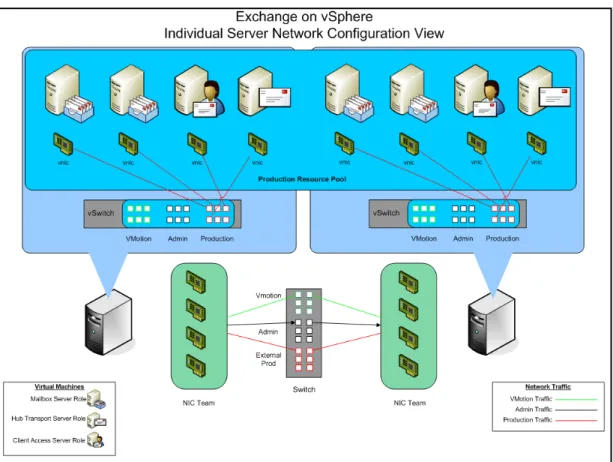
2.4.3 Sample Exchange Virtual Network Configuration
Best Practices Guide Figure 5 illustrates how networking is handled at the ESX level. Each ESX host must have virtual
switches architected to handle the type of network traffic that will be assigned to each of the different virtual machines. The figure represents a sample configuration where the production resource pool is split between two physical servers (to reflect redundancy for HA considerations). From a networking
perspective, make sure that production environment network traffic remains separate from VMware VMotion and Admin traffic. An effective way to handle this is by introducing VLAN technology to logically separate the traffic.
Each virtual machine acts independently, and remains isolated until networking is configured. What makes the environment different than that in the physical world is that it must have an internal network configured to establish communication between virtual machines residing on the same physical ESX host. This network traffic is handled through the virtual switch.
Each physical NIC can be configured to connect directly to an assigned VLAN, but the VMware VMotion and Admin networks are not used as heavily as production networks. One practice is to team all the NICs on the ESX host, connect them to trunk ports on the switch, and use VLAN tagging to direct the traffic at the switch level. This allows for better bandwidth utilization and frees up server capacity for production traffic when the VMware VMotion and Admin VLANs are not in heavy use.
Best Practices Guide
3. Exchange Performance on vSphere
3.1 Overview
Since 2006, VMware and its partners have used testing to successfully demonstrate the viability of running Exchange on the VMware Infrastructure platform. This testing has been confirmed by
organizations that have deployed Exchange 2003, 2007, and 2010 in virtualized production environments and now benefit from the considerable operational advantages and cost savings. Some customers have even virtualized their entire Exchange 2010 environment and have carefully designed their vSphere infrastructure to accommodate application performance, scalability, and availability requirements. Exchange Server 2010 is proving to be an even better candidate for virtualization than its predecessors. With up to 50% reduction in disk I/O from Exchange 2007 and many of the mailbox services being offloaded onto the Client Access Server role, the Exchange 2010 Mailbox Server role is lightweight, fast, and ready for virtualization. The shift towards running Exchange in virtual machines is a result of
advancements in three key areas:
• Architectural improvements of Exchange Server 2010 have drastically increased memory utilization and reduced disk I/O load by 50 percent or more in many cases, addressing many of the shortcomings found in Exchange 2003 and 2007.
• Advances in server hardware such as multi-core processors, higher memory density, and advances in storage technology are far outpacing the performance requirements for today’s applications, including Exchange. Virtualization becomes an effective way to leverage the full power of these systems.
• The advances in Exchange Server 2010 and server hardware technology have coincided with
advances in vSphere. Virtual machines can now support up to 255GB RAM and 8 vCPUs, and are capable of running even the largest Exchange mailbox servers. VMware ESX hosts can now take advantage of up to 64 CPUs and 1TB of physical RAM. Network improvements such as Jumbo Frames and TCP Segment Offload have lowered overall CPU usage. These and other enhancements make vSphere capable of meeting performance requirements for even the most demanding
Exchange workloads.
Third-party testing of Exchange Server 2010 in virtual operation has been completed with Microsoft’s JetStress and LoadGen tools, the standard tools for Exchange performance analysis. These tests show that performance for a virtualized Exchange server is comparable to a non-virtualized server running on the same hardware. This proved to be true for all Exchange Server 2010 server roles, including the mailbox server. With concerns over relative performance eliminated, many more Exchange administrators are finding the flexibility, enhanced availability, and lower costs associated with virtualization very
Best Practices Guide
3.2 Key Performance Considerations
A variety of factors can affect Exchange Server 2010 performance on vSphere, including processor and memory allocation to the guest virtual machine, storage layout/design, virtual machine placement, and high availability methods, to name a few. The following are some tips for ensuring the best possible performance:
• Fully understand your organization’s business and technical requirements for implementing Exchange.
• Fully understand the Exchange workload requirements. Current workloads can be measured using
t
• Size for I/O and not just capacity. Dedicating the appropriate number of spindles (disks) can greatly affect performance of an Exchange virtual machine.
• Use Microsoft sizing and configuration guidelines for the Exchange virtual machines.
• Follow the best practices in Section 2 of this document to ensure that the ESX host environment is optimized for enterprise applications such as Exchange.
3.3 Performance Testing
Every Exchange environment is different, with varying business and technical requirements, a plethora of server and storage options, and requirements for integrating with third-party software solutions such as anti-virus, anti-spam, PDA messaging, and so on. Due to the many variables, it is highly recommended that each organization test performance on their particular mix of server, storage, and software to determine the best design for their Exchange environment. In addition, several VMware server and storage partners have performed testing to validate Exchange performance on vSphere. Both of these options are discussed in this section.
3.3.1 Internal Performance Testing
Microsoft provides tools to measure the performance of Microsoft Exchange Server architectures. LoadGen is used to measure performance of both Exchange Server 2007 and Exchange Server 2010. For both versions a storage qualification tool, JetStress, can be used to evaluate the storage
configuration.
Because in-guest time is subject to minute fluctuations based on system load, VMware strongly
discourages executing any performance analysis tool inside a virtual machine. Accurate measurements are best attained by creating tools that can use the host timer, or by using tests such as LoadGen that contain client/server architectures. For client server tests, the server-under-test may be on a virtual machine while the client is on a native system. This results in accurate measurements at the client. JetStress, however, does not provide a mechanism for using native timing measurements. The accuracy of JetStress measurements is subject to load on the hypervisor, the processor model, the version of ESX, and has been known to display a bias. This means that JetStress can report performance metrics that outperform native. Conclusions about the actual performance of this tool in the virtual machine are difficult to find, but it is best to consider JetStress results as broad indicators of performance. Generally speaking, Jetstress results run on newer processors with vSphere 4 or later will show minimal and tolerable error.
Best Practices Guide
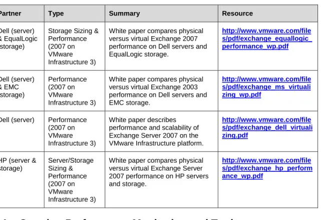
3.3.2 Partner Performance Testing
VMware and its OEM partners have been working together for years to characterize Exchange performance. The following table summarizes our performance testing for the last two versions of Exchange running on VMware Infrastructure 3 and vSphere.
Table 2. Performance Testing Summary
Partner Type Summary Resource
Dell (server) & EqualLogic (storage)
Storage Sizing & Performance (2007 on VMware Infrastructure 3)
White paper compares physical versus virtual Exchange 2007 performance on Dell servers and EqualLogic storage. Dell (server) & EMC (storage) Performance (2007 on VMware Infrastructure 3)
White paper compares physical versus virtual Exchange 2003 performance on Dell servers and EMC storage.
Dell (server) Performance (2007 on VMware Infrastructure 3)
White paper describes performance and scalability of Exchange Server 2007 on the VMware Infrastructure platform.
HP (server & storage) Server/Storage Sizing & Performance (2007 on VMware Infrastructure 3)
White paper compares physical versus virtual Exchange Server 2007 performance on HP servers and storage.
3.4 Ongoing Performance Monitoring and Tuning
Traditional Exchange Server performance monitoring leverages the Microsoft Windows performance monitor tool PerfMon to collect statistics. Exchange integrates with PerfMon to provide familiar counters that indicate system performance. But, as with all in-guest measurement tools, time-based performance measurements are subject to error. The degree to which the measurements are inaccurate depends on the total load of the ESX host. But, generally it is safe to assume the results are no more than 10% in error if CPU utilization stays below 80%.
Exchange administrators should pay close attention to the counters listed in Table 3. Refer t
Best Practices Guide
Table 3. Performance Counters of Interest to Exchange Administrators
Subsystem esxtop Counters vCenter Counter
CPU %RDY
%USED
Ready (milliseconds in a 20,000 ms window) Usage
Memory %ACTV
SWW/s SWR/s
Active Swapin Rate Swapout Rate Storage ACTV
DAVG/cmd KAVG/cmd
Commands Device Latency Kernel Latency Network MbRX/s
MbTX/s
packetsRx packetsTx
This table indicates a few key counters that should be added to the list of inspection points for Exchange administrators. Of the CPU counters, the total used time indicates system load. Ready time indicates overloaded CPU resources. A significant swap rate in the memory counters is a clear indication of a shortage of memory, and high device latencies in the storage section point to an overloaded or
misconfigured array. Network traffic is not frequently the cause of most Exchange performance problems except when large amounts of iSCSI storage traffic are using a single network line. Check total
throughput on the NICs to see if the network is saturated.
3.5 vSphere Performance Features and Exchange
VMware virtual machines always benefit from newer versions of vmxnet, so we recommend the newest version of vmxnet for Microsoft Exchange virtual machines. VMware’s paravirtualized SCSI driver is optimized for high IO environments, but need not be used when a virtual machine generates less than
2000 IOPS. For more information s
vSphere 4 also introduced support for second-generation virtualization assist in Intel processors. As with VMware Infrastructure 3, which contained support for similar functionality from AMD, VMware
recommends using this additional memory management for most workloads. AMD’s memory
management, called Rapid Virtualization Indexing (RVI), can be leveraged with ESX 3.5 or newer. Intel’s memory management, called Extended Page Tables (EPT), requires ESX 4.0 or newer.
Best Practices Guide
4. Exchange 2010 Capacity Planning
4.1 Capacity Planning Process Overview
Sizing of an Exchange 2010 environment is a complex process with many variables including business requirements, anticipated mailbox workloads, and hardware platform, to name a few. The good news is that sizing an Exchange 2010 environment on vSphere is nearly the same as sizing for physical servers. First, you must decide whether or not you’ll be clustering the mailbox servers. If you choose to use standalone mailbox servers protected by VMware HA, use the “building block” approach defined in Section 4.6.1. If you decide to implement Database Availability Groups (DAGs), use the “DAG” approach described in Section 4.6.2.
Storage sizing and configuration can vary depending on the storage array used and many vendors have unique enhancements to the storage solution that can increase availability, speed recovery, and enhance performance, etc. To optimize performance and take advantage of these features, it is highly
recommended that the storage partner be included in the design effort.
There are many facets to an Exchange 2010 deployment besides sizing. Exchange 2010 can be
deployed into some very complex, multi-site architectures that should be designed with the assistance of an Exchange expert, whether that person is an internal company resource or a partner with experience deploying both Exchange and vSphere.
When sizing virtual machines, note the following:
• Smaller virtual machines (CPU and RAM) can be moved faster with VMotion than larger virtual machines. For example, a mailbox server virtual machine with 2 vCPU and 9GB RAM can move to another ESX host with VMotion much quicker than a virtual machine with 4 vCPU and 32GB RAM. Although larger virtual machines can support more users, smaller virtual machines can be more agile in a vSphere environment.
• Size CPU and RAM resources conservatively, and only adjust as required. One of the primary benefits a virtual machine provides is the ability to allocate more CPU or RAM at any time. This means administrators can size their servers based on realistic estimates and only increase resources as required.
• When deciding on the number and size of virtual machine building blocks, consider how this will impact licensing costs for the operating system and applications. Depending on your licensing
agreements, more virtual machines may increase licensing costs. Find the right balance between cost and flexibility for your environment.
Best Practices Guide
4.2 Mailbox Server: Planning for CPU
4.2.1 Passive Database Overheads
The new Database Availability Group (DAG) feature in Exchange 2010 necessitates a different approach to sizing the Mailbox Server role, forcing the administrator to account for both active and passive
mailboxes. Mailbox Servers that are members of a DAG can host one or more passive databases in addition to any active databases for which they may be responsible.
Each passive database adds an additional 10% to the CPU requirements of the mailbox server hosting the active copy
Figure 6
.
illustrates this principle. We have three Exchange mailbox servers, each with an active database (DB1a denotes database 1 active) and two passive databases from the other two mailbox servers (DB1p denotes database 1 passive). Each passive copy of DB1a requires 10% extra processing on the server hosting DB1a, for a total of 20% extra CPU overhead.
So each mailbox server in this example requires 20% additional processing power
to account for passive database copies.
Figure 6. Passive Database Overheads
4.2.2 Exchange Server Minimums and Recommended Maximums
Best Practices Guide
Table 4. Exchange Server Minimums and Recommended Maximums
Exchange 2010 server role Minimum Recommended Maximum
Edge Transport 1 x processor core 12 x processor
cores
Hub Transport 1 x processor core 12 x processor
cores
Client Access 2 x processor core 12 x processor
cores
Unified Messaging 2 x processor core 12 x processor cores
Mailbox 2 x processor
core
12 x processor cores
Client Access/Hub Transport combo-role (Client Access and Hub Transport roles running on the same physical server)
2 x processor core 12 x processor cores
Multi-role (Client Access, Hub Transport and Mailbox server roles running on the same physical server)
2 x processor cores
24 x processor cores
4.2.3 Megacycles
A Megacycle is a unit of measurement used to represent processor capacity. To give a rough estimate, a 1GHz processor can produce approximately 1,000 megacycles of CPU throughput. For a larger example, a two-socket, quad-core server (eight cores) with 3.33GHz CPUs can produce approximately 26,400 megacycles.
Each Exchange user placed on the server subtracts from this capacity at varying rates depending on the activity and size of the mailbox. Don’t forget that we must take into account CPU requirements for both the active and passive mailboxes that are hosted on the server (see Section 4.1).
From Microsoft TechNet
Megacycles are estimated based on a measurement of Intel Xeon x5470 3.33GHz processors (2 x 4 core arrangement). A 3.33-GHz processor core = 3,300 megacycles of performance throughput. Other processor configurations can be estimated by comparing this measured platform to server platforms tested by the Standard Performance Evaluation Corporation
Best Practices Guide
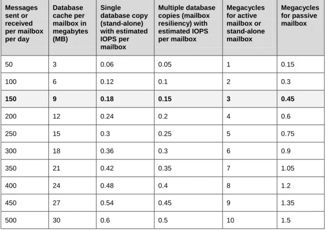
4.2.4 User Profile and Message Activity
Each mailbox (active or passive) has some degree of impact to the overall CPU capacity of the mailbox server, depending on the activity level of the mail user. For example, a mailbox that sends/receives 150 messages a day generate 3 megacycles of CPU activity if the mailbox is in an active database, or .45 megacycles of activity if the mailbox is in a passive database.
Also listed in Table 5 are I/O numbers to aid in storage planning. In the previous example, if we choose to run a standalone mailbox server, we can expect .18 IOPS per mailbox. If we choose to cluster with DAGs that number drops to .15 IOPS, but remember that there is an impact on the passive DAG node.
Table 5. Per Mailbox Database Cache, IOPS, and CPU Estimates Based on User Profile and Message Activity Messages sent or received per mailbox per day Database cache per mailbox in megabytes (MB) Single database copy (stand-alone) with estimated IOPS per mailbox Multiple database copies (mailbox resiliency) with estimated IOPS per mailbox Megacycles for active mailbox or stand-alone mailbox Megacycles for passive mailbox
50 3 0.06 0.05 1 0.15
100 6 0.12 0.1 2 0.3
150 9 0.18 0.15 3 0.45
200 12 0.24 0.2 4 0.6
250 15 0.3 0.25 5 0.75
300 18 0.36 0.3 6 0.9
350 21 0.42 0.35 7 1.05
400 24 0.48 0.4 8 1.2
450 27 0.54 0.45 9 1.35
500 30 0.6 0.5 10 1.5
These metrics, combined with an understanding of the client protocols used to access Exchange resources (Microsoft Outlook, Outlook Anywhere, Outlook Web Access, ActiveSync, and BlackBerry devices, etc.), provide the foundation for planning Exchange CPU, memory, storage, and network requirements. The benefit of profiling Exchange users in this way is that it is platform independent. These same metrics can be used for IBM Lotus Notes, Novell GroupWise, or any other messaging platform to plan resource requirements for an Exchange Server 2007 migration.
Best Practices Guide
4.2.5 Designing for Peak Utilization
It is recommended that standalone servers with only the mailbox role be designed to not exceed 70% utilization during peak period. If deploying multiple roles on the server, the mailbox role should be designed not to exceed 35%.
For solutions leveraging mailbox resiliency, it is recommended that the configuration not exceed 80% utilization after a single or double member server failure when the server only has the mailbox role installed. If deploying multiple roles on the server, then the mailbox role should be designed not to exceed 40%.
CPU utilization is determined by taking the CPU Megacycle Requirements and dividing it by the total number of megacycles available on the server (which is based on the CPU and number of cores).
4.3 Mailbox Server: Planning for Memory
4.3.1 Minimum and Recommended Memory
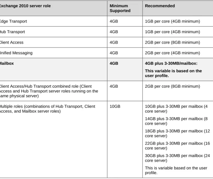
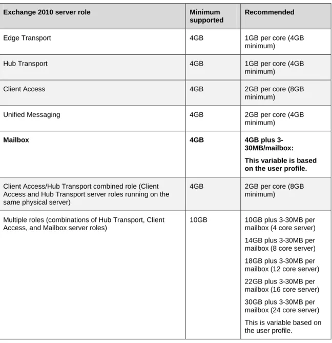
Table 6. Memory Configurations for Exchange 2010 Servers Based on Installed Server Roles
Exchange 2010 server role Minimum Supported
Recommended
Edge Transport 4GB 1GB per core (4GB minimum)
Hub Transport 4GB 1GB per core (4GB minimum)
Client Access 4GB 2GB per core (8GB minimum)
Unified Messaging 4GB 2GB per core (4GB minimum)
Mailbox 4GB 4GB plus 3-30MB/mailbox:
This variable is based on the user profile.
Client Access/Hub Transport combined role (Client Access and Hub Transport server roles running on the same physical server)
4GB 2GB per core (8GB minimum)
Multiple roles (combinations of Hub Transport, Client Access, and Mailbox server roles)
10GB 10GB plus 3-30MB per mailbox (4 core server)
14GB plus 3-30MB per mailbox (8 core server)
18GB plus 3-30MB per mailbox (12 core server)
Best Practices Guide
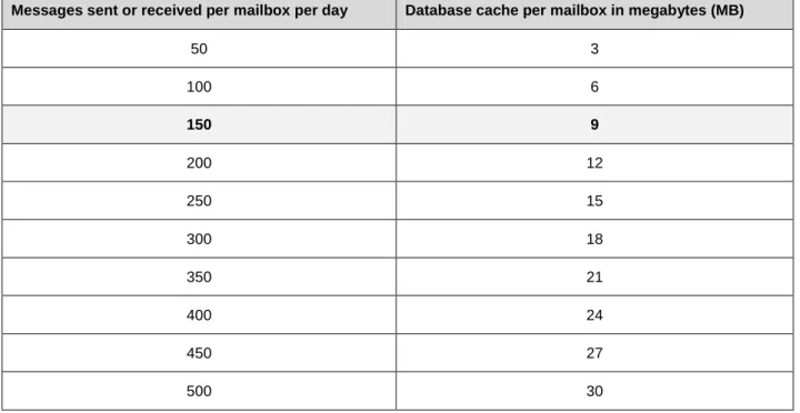
4.3.2 Determining Database Cache Size
The first step in planning for Mailbox Server memory is to determine the amount of required database cache by multiplying the mailbox count by the memory requirements based on the user profile. For example, 4,000 users sending/receiving 150 messages per day will require 36GB of database cache. (4000 * 9MB = 36GB).
Table 7. Per Mailbox Database Cache, IOPS, and CPU Estimates Based on User Profile and Message Activity
Messages sent or received per mailbox per day Database cache per mailbox in megabytes (MB)
50 3
100 6
150 9
200 12
250 15
300 18
350 21
400 24
450 27
Best Practices Guide
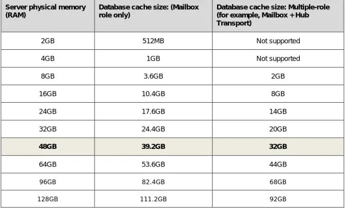
4.3.3 Determining Total Memory
The next step is to determine the amount of required physical memory by determining which server configuration provides 36GB of database cache. For example, a single role Mailbox server with 48GB of physical RAM will provide 39.2GB of database cache. Therefore, 48GB of physical RAM is the ideal memory configuration based on this mailbox count/user profile.
Table 8. Determining Total Memory
Server physical memory (RAM)
Database cache size: (Mailbox role only)
Database cache size: Multiple-role (for example, Mailbox + Hub Transport)
2GB 512MB Not supported
4GB 1GB Not supported
8GB 3.6GB 2GB
16GB 10.4GB 8GB
24GB 17.6GB 14GB
32GB 24.4GB 20GB
48GB 39.2GB 32GB
64GB 53.6GB 44GB
96GB 82.4GB 68GB
128GB 111.2GB 92GB
4.4 Mailbox Server: Planning for Storage
Each Exchange server role has unique storage requirements with respect to throughput (IO) and capacity. Planning storage configurations for the mailbox server role requires knowledge of the existing user profile. Microsoft has defined user profiles by average messages sent and received per day per user. This allows for more accurate planning when migrating from email systems other than Microsoft Exchange. The user profile has a direct impact on overall IO requirements, and knowing these
requirements can help you and your storage vendors in designing an optimal storage solution. In addition to the average mail sent and received; mobile devices, archiving solutions, and anti-virus programs should be taken into consideration as contributors to overall IO. T
Best Practices Guide
4.5 Hub Transport and Client Access Server Planning
4.5.1 Server Role Ratios by Processor Core
Microsoft provides some general guidelines to plan the number of Hub Transport and Client Access Servers based on processor core ratio to the mailbox server role. These guidelines are meant as a general rule, but your availability requirements, client protocol usage, and unique configuration requirements may indicate more optimal configurations.
Note
In Exchange 2010, the CAS server plays a more important role in the architecture. The CAS ratios have changed from Exchange 2007.The following table summarizes the Microsoft-recommended guidelines.
Table 9. Recommended Server Role Ratios Based on Processor Core
Server role ratio Recommended processor core ratio
Mailbox: Hub 7:1 (No antivirus scanning on hub) 5:1 (With antivirus scanning on hub) Mailbox: Client Access 4:3
Mailbox: Combined Hub/CAS 1:1
When doing processor core ratios, remember to factor in the expected peak utilization of your mailbox servers. For example, Microsoft recommends 70% peak utilization for a standalone mailbox server. If your mailbox server is configured with 6 cores at 70% peak utilization, the mailbox server is actually using 6*.70 or 4.2 cores. Use this new number to calculate Hub and CAS core ratios:
• 6 (total number of mailbox cores) * .70 peak utilization = 4.2 (utilized mailbox cores) • 4.2 (utilized mailbox cores)/5:1 = .84 Hub Transport cores (with anti-virus scanning) • 4.2 (utilized mailbox cores)/4:3 = 3.2 CAS cores
Best Practices Guide
4.5.2 Memory Requirements by Processor Core Count
Microsoft provides guidance for planning the memory requirements for the Hub Transport and Client Access Servers based on the number of processor cores recommended for each sever role. The following table summarizes the guidelines that Microsoft recommends.
Table 10. Recommended Server Role Memory Based on Processor Core
Exchange 2010 server role Minimum supported
Recommended
Edge Transport 4GB 1GB per core (4GB
minimum)
Hub Transport 4GB 1GB per core (4GB
minimum)
Client Access 4GB 2GB per core (8GB
minimum)
Unified Messaging 4GB 2GB per core (4GB
minimum)
Mailbox 4GB 4GB plus
3-30MB/mailbox: This variable is based on the user profile.
Client Access/Hub Transport combined role (Client Access and Hub Transport server roles running on the same physical server)
4GB 2GB per core (8GB minimum)
Multiple roles (combinations of Hub Transport, Client Access, and Mailbox server roles)
10GB 10GB plus 3-30MB per mailbox (4 core server) 14GB plus 3-30MB per mailbox (8 core server) 18GB plus 3-30MB per mailbox (12 core server) 22GB plus 3-30MB per mailbox (16 core server) 30GB plus 3-30MB per mailbox (24 core server) This is variable based on the user profile.
Best Practices Guide
4.6 Scaling Exchange for the Enterprise
4.6.1 The Building Block Approach (Standalone Mailbox Servers)
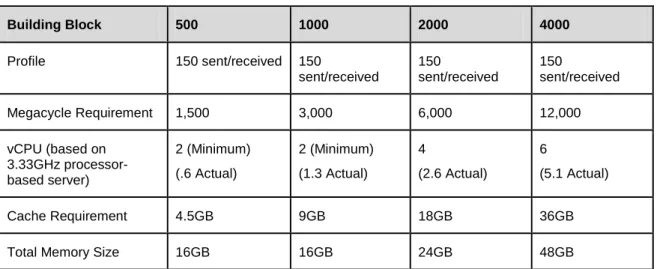
The building block approach is a recommended best practice for creating a standalone Exchange Mailbox Servers running on vSphere using pre-sized virtual machine configurations. Exchange servers that have been divided into virtual machine building blocks (as opposed to larger, monolithic Exchange servers) can simplify server sizing during the initial deployment and create a highly scalable solution using virtual machines with predictable performance patterns. Testing by VMware and its partners has focused on four primary sizes for mailbox virtual machine building blocks consisting of 500, 1000, 2000, and 4000 users. These configurations have known performance profiles that can be leveraged for rapid Exchange server sizing as well as easily scaling environments as additional Exchange servers need to be brought online. The following table presents some pre-sized virtual machine building block examples designed to host mailboxes with an average of 150 messages sent/received per day. The same principles are used for sizing profiles ranging from 50 to 550 messages sent/received per day.
Table 11. Building block CPU and RAM requirements for mailboxes with 150 messages sent/received per day
(based on information from
Building Block 500 1000 2000 4000
Profile 150 sent/received 150
sent/received
150
sent/received
150
sent/received
Megacycle Requirement 1,500 3,000 6,000 12,000
vCPU (based on 3.33GHz processor-based server) 2 (Minimum) (.6 Actual) 2 (Minimum) (1.3 Actual) 4 (2.6 Actual) 6 (5.1 Actual)
Cache Requirement 4.5GB 9GB 18GB 36GB
Total Memory Size 16GB 16GB 24GB 48GB
The sizing process begins with understanding and applying Microsoft guidelines for each server role, as represented by the following high-level processes:
• Design the mailbox server building block.
o Define current workloads using t
o Choose an appropriate (500, 1000, 2000, and 4000 user blocks have been tested and validated, although larger building blocks may be possible).
o Apply Microsoft guidelines to determine the CPU requirements o Apply Microsoft guidelines to
.
Best Practices Guide • Design the peripheral server roles.
o Determine how many mailbox server building blocks are needed. o Calculate the number of mailbox server processor cores.
o Use Microsoft Guidelines for Server Role Ratios to calculate processor and memory requirements for the Hub Transport roles.
o Use Microsoft Guidelines for Server Role Ratios to calculate processor and memory requirements for the Client Access Server roles.
• Allocate one or more virtual machines for each server role to satisfy the previously calculated number of processor cores and amount of memory.
• Determine how the virtual machines will be distributed across ESX hosts.
• Aggregate virtual machine requirements plus some overhead to size each ESX host. The overhead is important if you want to minimize the performance hit during the loss of one of your ESX hosts. A typical guideline when choosing the number of required hosts is n+1, where n is the number of hosts required to run the workload at peak utilization. N+1 allows you to design for the possibility of losing one host from your VMware cluster without taking a huge performance hit during failover.
4.6.2 The DAG Approach
The new Database Availability Group (DAG) feature in Exchange 2010 necessitates a different approach to sizing the Mailbox Server role, forcing the administrator to account for both active and passive mailboxes. Mailbox Servers that are members of a DAG can host one or more passive databases in addition to any active databases for which they may be responsible.
The sizing process begins with understanding and applying Microsoft’s guidelines for each server role, as represented by the following high-level processes:
• Design the Mailbox Server DAG nodes.
o Define current workloads using t
o To greatly simplify the capacity planning process, utilize the
o Alternatively, if you prefer a manual process:
Apply Microsoft guidelines to determine the CPU and memory requirements. Inputs will include, number of mailboxes, mailbox profile, number of servers in the DAG, number of passive database copies, and several other custom parameters.
Utilize t
determine storage requirements. • Design the peripheral server roles.
o T
Best Practices Guide Use the modified number of mailbox cores and Microsoft Guidelines for Server Role Ratios to
calculate processor and memory requirements for the Client Access Server roles.
• Allocate one or more virtual machines for each server role to satisfy the previously calculated number of processor cores and amount of memory.
• Determine how the virtual machines will be distributed across ESX hosts.
• Aggregate virtual machine requirements plus some overhead to size each ESX host. The overhead is important if you want to minimize the performance hit during the loss of one of your ESX hosts. A typical guideline when choosing the number of required hosts is n+1, where n is the number of hosts required to run the workload at peak utilization. N+1 allows you to design for the possibility of losing one host from your VMware cluster without taking a huge performance hit during failover.
4.7 vSphere Limitations
Although vSphere can support very large virtual machines, there are some limits that you should be aware of when Capacity Planning for Exchange. Below are some of the most common configurations to
be aware of. Complete documentation can be found at t
on VMware.com.
• vSphere virtual machines are limited to 8 vCPU and 255GB of RAM. • Each ESX host can only accommodate up to 255 LUNs.
• Each vSphere LUN is limited to 2TB (without SAN extents).
In the sizing examples below and in the Design and Sizing Examples document, we’ve taken the ESX limitations into account, especially when configuring storage. For example, in the DAG sizing section, we limited database sizes to 1TB to ensure that we didn’t come too close to our 2TB LUN limit. In addition, we limited virtual machine configurations to 8 vCPU based on the vSphere maximum.
Best Practices Guide
5. Sizing Examples
Every environment is different and some organizations use email more heavily than others. To accurately determine your mailbox profile requirements, use th also highly recommended that you work with a partner that is extremely well-versed in Exchange Architecture to design for proper performance in your specific environment.
Note that these examples do not take into account a particular storage solution. Many VMware storage partners have performed extensive testing on building blocks of varying capacities and workloads. Please refer to the Microsoft Exchange 2010 on VMware: Partner Resource Catalog
5.1 Standalone Mailbox Server – 16,000 Users (150 sent/received)
for storage-specific implementation details.Using the Microsoft sizing guidelines and the building block approach, we apply the formula to size a 16,000-user environment with mailbox profiles measured at 150 messages sent/received per user per day. The mailboxes are distributed across four mailbox server building blocks of 4,000 users each. The following calculations are meant to serve as an example of the sizing process—every organization’s implementation details will vary.
In our example, we use the following mailbox profile: • 150 messages sent/received per day
• Average message size of 75 KB • 2048MB mailbox quota
5.1.1 Calculate Mailbox Server CPU Requirements (4,000 Users/VM)
Microsoft guidelines recommend using megacycles to determine the amount of CPU required by the mailbox server (see Section 4.1.3). Each user consumes resources on the processor at varying rates depending on message activity. Because we are not implementing Database Availability Groups in this example, we can use the guidance for stand-alone mailbox servers from Table 12.
Table 12. Mailbox Server CPU Recommendations
Messages sent or received per mailbox per day Megacycles for stand-alone mailbox
50 1
100 2
150 3
200 4
Best Practices Guide
The first step in sizing our 4,000-user building block is to apply these Microsoft guidelines to determine the CPU requirements.
Example:
Your organization plans to support 16,000 users with 4,000 mailboxes per Exchange Mailbox Server and a 2GB mailbox quota. You have used the Exchange Server Profile Analyzer to determine that your users average 150 messages sent and received per day, with an average message size of 75 KB. The standard hardware build includes 16 core servers (4x4) with each CPU at 3.33GHz.
• 16,000 mailboxes/4,000 mailboxes per server = 4 mailbox servers
• 4,000 mailboxes per server * 3 megacycles per active mailbox = 12,000 megacycles required
• Each 3.33GHz processor core can produce 3,330 megacycles
• Microsoft recommends 70% peak utilization of a standalone mailbox server • 12,000 megacycles required/.70 = 17,143 adjusted megacycles required
• 17,143 megacycles/3,330 = 6 processor cores per server (rounded up from 5.15 actual) • 4 mailbox servers x 6 processor cores per server = 24 processor cores
• Our mailbox servers will utilize 60% of their processing capability at peak utilization. Adjusting the number of virtual processors to 5 would help increase processor utilization.
Best Practices Guide
5.1.2 Calculate Mailbox Server Memory Requirements (4,000 Users/VM)
Use the first table to determine the required amount of database cache and the second table to pick the total server memory that will satisfy the database cache requirement.
Table 13. Mailbox Server Database Cache Requirements
Messages sent or received per mailbox per day Database cache per mailbox in megabytes (MB)
50 3
100 6
150 9
200 12
250 15
300 18
350 21
400 24
450 27
500 30
Table 14. Default mailbox database cache sizes
Server physical memory (RAM)
Database cache size: (Mailbox role only)
Database cache size: Multiple-role (for example, Mailbox + Hub Transport)
2GB 512MB Not supported
4GB 1GB Not supported
8GB 3.6GB 2GB
16GB 10.4GB 8GB
Best Practices Guide
5.1.3 Calculate Mailbox Server Storage Requirements
Table 15. Environment Configuration
Table 16. Data Configuration
Exchange Data Configuration Value
Data Overhead Factor 20%
Mailbox Moves/Week Percentage 1% Dedicated Maintenance/Restore LUN? Yes LUN Free Space Percentage 20%
Exchange Environment Configuration Value
Global Catalog Server Architecture 64-bit Server Multi-Role Configuration (MBX+CAS+HT) No High Availability Deployment No Site Resiliency Deployment No
Number of Mailbox Servers 4
Global Catalog Server Architecture 64-bit Server Multi-Role Configuration (MBX+CAS+HT) No
Example:
Given our previous example of 16,000 mailboxes with 4,000 mailboxes per server with each mailbox sending/receiving 150 messages per day:
• 9MB x 4,000 mailboxes = 36GB required database cache
• According to the Default mailbox database cache sizes table, we need 48GB of total memory in the mailbox server to provide 39.2GB of database cache. This will satisfy the 36GB requirement.
Best Practices Guide
Table 17. Mailbox Configuration
Tier-1 User Mailbox Configuration Value
Total Number of Tier-1 User Mailboxes 16000 Projected Mailbox Number Growth Percentage 0% Total Send/Receive Capability/Mailbox/Day 150
messages Average Message Size (KB) 75
Mailbox Size Limit (MB) 2048
Personal Archive Mailbox Size Limit (MB) 0 Deleted Item Retention Window (Days) 14
Single Item Recovery Enabled
Calendar Version Storage Enabled IOPS Multiplication Factor 0.00 Desktop Search Engines Enabled (for Online
Mode Clients)
No
Predict IOPS Value? Yes
Table 18. Backup Configuration
Backup Configuration Value
Backup Methodology Software VSS Backup/Restore Backup Frequency Weekly Full/Daily Incremental Database and Log Isolation Configured No
Backup/Truncation Failure Tolerance 3 Network Failure Tolerance (Days) 0
Best Practices Guide
Table 19. Storage Configuration
Disk Configuration Disk Capacity Disk Type
Database 300GB 10K RPM FC/SCSI/SAS 3.5"
Log 300GB 10K RPM FC/SCSI/SAS 3.5"
Restore LUN 300GB 10K RPM FC/SCSI/SAS 3.5"
Table 20. Processor Configuration
Server Configuration Processor Cores/Server Megacycles/Core
Mailbox Servers 6 3330
5.1.3.1. Mailbox Server Role Storage Requirements Calculator v6.3 Results
Using the Exchange Server 2010 Mailbox Server Role Storage Requirements Calculator version 6.3 and the above variables, our mailbox server storage configuration is summarized as follows.
Table 21. Mailbox Server Storage Results
Output Value
Database/log configuration (per server) 58 databases per server
190GB database size + overhead 9GB log size + overhead
Database LUN design (per server) 19 LUNs recommended (9 DB, 9 Log, 1 Restore) 7 databases per LUN
DB1-DB7: 1833GB DB LUN/80GB Log LUN DB8-DB14: 1833GB DB LUN/80GB Log LUN DB15-DB21: 1833GB DB LUN/80GB Log LUN DB22-DB28: 1833GB DB LUN/80GB Log LUN DB29-DB35: 1833GB DB LUN/80GB Log LUN DB36-DB42: 1833GB DB LUN/80GB Log LUN DB43-DB49: 1833GB DB LUN/80GB Log LUN DB50-DB56: 1833GB DB LUN/80GB Log LUN DB57-DB58: 524GB DB LUN/23GB Log LUN Restore LUN: 1747GB
Best Practices Guide Restore LUN Disks per Server (RAID 5)
-12 x 300GB/10K RPM FC/SCSI/SAS 3.5"
5.1.4 Mailbox Server Summary (4,000-User/150 sent/received)
The following table summarizes the resource requirements for our 4,000-user building block.
Table 22. 4,000-User Building Block Requirements (150 sent/received)
Exchange Role Physical Resources (per server)
Mailbox server (4 nodes) CPU: 6 cores
Memory: 48GB
OS and Application File Storage:
64GB (OS & application files)
Database Storage
110 x 300GB/10K RPM FC/SCSI/SAS 3.5"
Log Storage
6 x 300GB/10K RPM FC/SCSI/SAS 3.5"
Restore LUN Storage
12 x 300GB/10K RPM FC/SCSI/SAS 3.5"
Network: 1Gbps
Example:
With a standalone mailbox server, Microsoft recommends placing logs on separate LUNs than their corresponding database files. Given our previous example of 16,000 mailboxes with 4,000 mailboxes per server with each mailbox sending/receiving 150 messages per day: • 58 databases per server
• 19 LUNs recommended per server (9 DB, 9 Log, 1 Restore) • 7 databases per LUN
• Physical Disk Requirements (per Server)
o Databases = 110 x 300GB/10K RPM FC/SCSI/SAS 3.5" o Log = 6 x 300GB/10K RPM FC/SCSI/SAS 3.5"