FINAL DRAFT UGANDA
STANDARD
FDUS 853
First Edition 2009-mm-dd Reference number FDUS 853: 2009Code of practice for solar water heating systems – Design, installation, testing, repair
and maintenance
Compliance with this standard does not, of itself confer immunity from legal obligations
A Uganda Standard does not purport to include all necessary provisions of a contract. Users are responsible for its correct application
© UNBS2009
All rights reserved. Unless otherwise specified, no part of this publication may be reproduced or utilised in any form or by any means, electronic or mechanical, including photocopying and microfilm, without prior written permission from UNBS.
Requests for permission to reproduce this document should be addressed to The Executive Director
Uganda National Bureau of Standards P.O. Box 6329 Kampala Uganda Tel: 256 41 4505995 Fax: 256 41 4286 123 E-mail: [email protected] Web: www.unbs.go.ug
FDUS 853: 2009
Contents
Page 1 Scope ...1 2 Normative references ...1 3 Definitions ...5 4 Legal requirements...9 5 Types of system ...106 Components for solar water heating systems ... 25
6.1 General ...25 6.2 Collectors...26 6.3 Storage tanks ...29 6.4 Pumps ...32 6.5 Piping...33 6.6 Controls ...35 6.7 Heat exchangers ...38 6.8 Heat-transfer fluids ...43 6.9 Expansion tank ...43
6.10 Valves, gauges and meters used in solar systems ...44
6.11 Air vent ...45
6.12 Temperature – pressure relief valve...45
6.13 Pressure relief valve ...46
6.14 Pressure gauge ...46
6.15 Vacuum breaker ...46
6.16 Isolation valves ...47
6.17 Drain valves...48
6.18 Check valves ...48
6.19 Mixing or tempering valve ...49
6.20 Anti-scald valve ...50 6.21 Freeze-protection valves ...50 6.22 Other components ...51 6.23 Water supply...52 7 Design considerations ... 52 7.1 General ...52
7.2 Collector design considerations ...52
7.3 System design considerations...54
7.4 Corrosion protection ...56
7.5 Heat transfer fluids ...57
7.6 Controllers and temperature sensors ...57
7.7 Other design factors ...58
8 Thermal performance of solar water heating systems... 58
8.1 General ...58
8.2 Collector class ...59
8.3 Effective collector area ...59
8.4 Hot water usage ...60
8.5 Preheat vessel size ...60
8.6 Collector mounting and location ...60
8.7 Climate ...61
8.8 Other factors...61
9.2 Electrical installation ... 62
9.3 Electrical safety... 62
9.4 Controls... 62
9.5 Avoidance of electrical interference... 62
9.6 Testing ... 62
10 Installation... 63
10.1 General ... 63
10.2 Pre-installation procedure... 63
10.3
Installation procedures ... 63
10.4 Collector subsystem installation ... 64
10.5.1 Collector positioning ... 65
11 Component installation ... 80
11.1 General ... 80
11.2 Piping, ducting and ancillary equipment ... 80
11.3 Storage tank installation ... 83
11.4 Pump, blowers and heat exchangers ... 85
11.5 Controls, sensors and safety devices ... 86
11.6 Freeze protection ... 88
11.7 Heat transfer fluids... 89
12 System installation checkout and start-up procedures ... 90
12.1 General ... 90
12.2 Pressure testing ... 90
12.3 Flushing the system ... 90
12.4 Testing the pump and controls ... 91
12.5 Cleaning up... 95
12.6 Homeowner’s manual and instructions... 95
13 Commissioning and documentation...96
13.1 Filling the system ... 96
13.2 Drain-down systems ... 96
13.3 Electrical and auxiliary equipment ... 96
13.4 Thermal insulation for the system... 97
13.5 Making good ... 97
13.6 Start-up and handing over ... 97
13.7 Recommended form of user's data sheet... 98
13.8
Post-commissioning checks ... 99
14 Problem assessment and system checkout ... 99
14.1 Problem assessment ... 99
14.2 The initial service call... 99
14.3 System records ... 100
14.4 Warranty coverage ... 100
14.5 Service history ... 101
14.6 Contractor liability ... 101
14.7 Overall checkout ... 101
14.8 Investigating consumer complaints — an example ... 102
14.9
Lifestyle analysis... 102 14.10 Common problems... 102 14.11 System checkout... 105 15 Troubleshooting checklist ... 113 16 Maintenance ... 119 17 Safety precautions ... 120
Annex A: Maintenance of weather-tightness……….…….123
FDUS 853: 2009
Annex C: Condensation and ventilation in roof spaces...128
Annex D: Method for calculating the thermal performance ...130
Annex E: Methods of pressure and leak testing of absorber plates...134
Annex F: Methods of type testing for collectors
...
135Annex G: Methods of testing for differential temperature control systems ...136
Annex H (informative) Solar thermal applications and technologies ...136
Annex I (informative) Solar basics...135
Annex J: Crome-dome collector siting aid...135
Annex K: Simplified sizing procedure for solar domestic hot water systems ...135
Annex L: Electric water heater circuitry ...136
Annex M: Volt-ohmmeter (VOM) or multimeter operation...132
Annex N: Solar system flow rates ...133
Annex P: Tools for service repair ...136
Foreword
Uganda National Bureau of Standards (UNBS) is a parastatal under the Ministry of Tourism, Trade and Industry established under Cap 323, of the Laws of Uganda. UNBS is mandated to co-ordinate the elaboration of standards and is
(a) a member of International Organisation for Standardisation (ISO) and
(b) a contact point for the WHO/FAO Codex Alimentarius Commission on Food Standards, and (c) the National Enquiry Point on TBT/SPS Agreements of the World Trade Organisation (WTO).
The work of preparing Uganda Standards is carried out through Technical Committees. A Technical Committee is established to deliberate on standards in a given field or area and consists of representatives of consumers, traders, academicians, manufacturers, government and other stakeholders.
Draft Uganda Standards adopted by the Technical Committee are widely circulated to stakeholders and the general public for comments. The committee reviews the comments before recommending the draft standards for approval and declaration as Uganda Standards by the National Standards Council.
Committee membership
The following organisations were represented on Subcommittee on Solar Energy, UNBS TC 13/SC 3, in the preparation of this standard:
• Renewable Energy Department, Ministry of Energy and Mineral Development
• Makerere University
• Incafex Solar Systems
• Battery Masters (U) Limited
• Equator-sun (U) Limited
• Ultratec (U) Limited
• Sonnerkraft Solar Systems
• Solar Masters
• Uganda National Plumbers Association
• Uganda Institute of Professional Engineers
FINAL DRAFT UGANDA STANDARD FDUS 853: 2009
Code of practice for solar water heating systems – Design,
installation, testing, repair and maintenance
1 Scope
1.1 This code of practice provides recommendations for solar water heating systems having collectors with liquid heat transfer media for heating water to help ensure adequate operation and safety. Design consideration, manufacture, handling, installation, operation and maintenance are included.
1.2 This code of practice applies regardless of the fraction of heating requirements supplied by solar energy, the type of conventional fuel used in conjunction with solar, or the heat transfer fluid (or fluids) used as the energy transport medium. However, where more stringent requirements are recommended by the manufacturer, these manufacturer requirements shall prevail.
1.3 This code of practice does not apply to space heating and swimming pools.
2 Normative
references
The following referenced documents are indispensable for the application of this Uganda Standard. For dated references, only the edition cited applies. For undated references, the latest edition of the referenced document (including any amendments) applies.
ISO 9059:1990, Solar energy – Calibration of field pyrheliometers by comparison to a reference pyrheliometer ISO 9060:1990, Solar energy – Specification and classification of instruments for measuring hemispherical solar and direct solar radiation
ISO 9459 -1:1993, Solar heating – Domestic water heating systems – Part 1: Performance rating procedure using indoor test methods
ISO 9459-2:1995, Solar heating – Domestic water heating systems – Part 2: Outdoor test methods for system performance characterization and yearly performance prediction of solar –only systems
ISO 9459-5:2007, Solar heating - Domestic water heating systems – Part 5: System performance characterization by means of whole-system test and computer simulation
ISO 9488:1999, Solar energy – Vocabulary
ISO 9553:1997, Solar energy – Methods of testing preformed rubber seals and sealing compounds used in collectors
ISO 9806-1:1994, Test methods for solar collectors – Part 1: Thermal performance of glazed liquid heating collectors including pressure drop
ISO 9806-2:1995, Test methods for solar collectors – Part 2: Qualification test procedures
ISO 9806-3:1995, Test methods for solar collectors – Part 3: Thermal performance of unglazed liquid heating collectors (sensible heat transfer only) including pressure drop
ISO 9808:1990, Solar water heaters — Elastomeric materials for absorbers, connecting pipes and fittings — Method of assessment
ISO 9845-1:1992, Solar energy — Reference solar spectral irradiance at the ground at different receiving conditions – Part 1: Direct normal and hemispherical solar irradiance for air mass 1.5
ISO 9846:1993, Solar energy — Calibration of a pyranometer using a pyrheliometer
ISO 9847:1992, Solar energy — Calibration of field pyranometers by comparison to a reference pyranometer ISO/TR 9901:1990, Solar energy — Field pyranometers — Recommended practice for use
ISO/TR 10217:1989, Solar energy — Water heating systems — Guide to material selection with regard to internal corrosion
ISO 4952:2006, Structural steels with improved atmospheric corrosion resistance
ISO 11303:2002, Corrosion of metals and alloys — Guidelines for selection of protection methods against atmospheric corrosion
ISO 11972:1998, Corrosion-resistant cast steels for general applications
US 854-1, Thermal solar systems and components — Solar collectors — General requirements US 854-2, Thermal solar systems and components — Solar collectors — Test methods
US 855-1:2009, Uganda Standard — Thermal solar systems and components — Factory made systems — General requirements
US 855-2:2009, Thermal solar systems components — Factory made systems — Test methods
US 857-1:2009, Thermal solar systems and components — Custom built systems —Part 3: General requirements
US 857-2:2009, Thermal solar systems and components — Custom built systems — Part 2: Test methods US 857-3:2009, Thermal solar systems and components — Custom built systems —Part 3: Performance characterization of stores for solar heating systems
US 862, Standard test method for determination of solar reflectance near ambient temperature using a portable solar reflectometer
US 861, Standard practice for evaluating absorptive solar receiver materials when exposed to conditions simulating stagnation in solar collectors with cover plates
US 856, Standard guide for on-site inspection and verification of operation of solar domestic hot water systems
ISO 559:1991, Steel tubes for water and sewage
ASTM B42:2002, Standard specification for seamless copper pipe, standard sizes
ISO 7598:1988, Stainless steel tubes suitable for screwing in accordance with ISO 7-1
ISO 49:1994, Malleable cast iron fittings threaded to ISO 7-1
FDUS 853: 2009
ASTM A126:2004, Standard specification for gray iron castings for valves, flanges, and pipe fittings
BS 417-2, Specification for galvanized low carbon steel cisterns, cistern lids, tanks and cylinders — Part 2: Metric units
ISO 12468-1:2003, External exposure of roofs to fire — Part 1: Test method
ISO 12468-2:2005, External fire exposure to roofs — Part 2: Classification of roofs
ISO 3008:2007, Fire-resistance tests — Door and shutter assemblies
IEC 60364 (All parts), Low-voltage electrical installations
ASTM E119:2007, Standard test methods for fire tests of building construction and materials
ASTM E861:1994(2007), Standard practice for evaluating thermal insulation materials for use in solar collectors
ISO 9774:2004, Thermal insulation for building applications — Guidelines for selecting properties
ISO 13787:2003, Thermal insulation products for building equipment and industrial installations — Determination of declared thermal conductivity
BS 864-2, Capillary and compression tube fittings of copper and copper alloy — Part 2: Specification for capillary and compression fittings for copper tubes
BS 864-3, Capillary and compression tube fittings of copper and copper alloy — Part 3: Compression fittings for polyethylene pipes
ISO 9906:1999, Rotodynamic pumps — Hydraulic performance acceptance tests — Grades 1 and 2
ISO 15783:2002, Seal-less rotodynamic pumps — Class II — Specification
ISO 9908:1993, Technical specifications for centrifugal pumps — Class III
ISO 9905:1994, Technical specifications for centrifugal pumps — Class I
BS 1565-2, Galvanized mild steel indirect cylinders, annular or saddle-back type — Part 2: Metric units
BS 1566-1, Copper indirect cylinders for domestic purposes — Part 1: Specification for double feed indirect cylinders
BS 1566-2, Copper indirect cylinders for domestic purposes — Part 2: Specification for single feed indirect cylinders
BS EN 1057, Copper and copper alloys — Seamless, round copper tubes for water and gas in sanitary and heating applications
BS 3198, Specification for copper hot water storage combination units for domestic purposes
ISO 4427-1:2007, Plastics piping systems — Polyethylene (PE) pipes and fittings for water supply — Part 1: General
ISO 4427-2:2007, Plastics piping systems — Polyethylene (PE) pipes and fittings for water supply — Part 2: Pipes
ISO 4427-5:2007, Plastics piping systems — Polyethylene (PE) pipes and fittings for water supply — Part 5: Fitness for purpose of the system
ISO 22391-1:2007, Plastics piping systems for hot and cold water installations — Polyethylene of raised temperature resistance (PE-RT) — Part 1: General
ISO 22391-5:2007, Plastics piping systems for hot and cold water installations — Polyethylene of raised temperature resistance (PE-RT) — Part 5: Fitness for purpose of the system
ISO 4422-1:1996, Pipes and fittings made of unplasticized poly(vinyl chloride) (PVC-U) for water supply — Specifications — Part 1: General
ISO 4422-2:1996, Pipes and fittings made of unplasticized poly(vinyl chloride) (PVC-U) for water supply — Specifications — Part 2: Pipes (with or without integral sockets)
ISO 4422-3:1996, Pipes and fittings made of unplasticized poly(vinyl chloride) (PVC-U) for water supply — Specifications — Part 3: Fittings and joints
ISO 4422-4:1997, Pipes and fittings made of unplasticized poly(vinyl chloride) (PVC-U) for water supply — Specifications — Part 4: Valves and ancillary equipment
ISO 4422-5:1997, Pipes and fittings made of unplasticized poly(vinyl chloride) (PVC-U) for water supply — Specifications – Part 5: Fitness for purpose of the system
EAS 205, Controls for household appliances
BS 4213:2004, Cisterns for domestic use — Cold water storage and combined feed and expansion (thermoplastic) cisterns up to 500 L — Specification
ISO 16422:2006, Pipes and joints made of oriented unplasticized poly(vinyl chloride) (PVC-U) for the conveyance of water under pressure — Specifications
BS 4814, Specification for expansion vessels using an internal diaphragm, for sealed hot water heating systems
ISO 15874-1:2003, Plastics piping systems for hot and cold water installations — Polypropylene (PP) — Part 1: General
ISO 15874-2:2003, Plastics piping systems for hot and cold water installations — Polypropylene (PP) — Part 2: Pipes
ISO 15874-5:2003, Plastics piping systems for hot and cold water installations — Polypropylene (PP) — Part 5: Fitness for purpose of the system
ISO 6242-1:1992, Building construction — Expression of users' requirements — Part 1: Thermal requirements
ISO 6242-2:1992, Building construction — Expression of users' requirements — Part 2: Air purity requirements
ISO 15493, Plastics piping systems for industrial applications — Acrylonitrile-butadiene-styrene (ABS), unplasticized poly(vinyl chloride) (PVC-U) and chlorinated poly(vinyl chloride) (PVC-C) — Specifications for components and the system — Metric series
ISO 727-1:2002, Fittings made from unplasticized poly(vinyl chloride) (PVC-U), chlorinated poly(vinyl chloride) (PVC-C) or acrylonitrile/butadiene/styrene (ABS) with plain sockets for pipes under pressure — Part 1: Metric series
FDUS 853: 2009
IEC 61000-3-2, Electromagnetic compatibility (EMC) — Part 3-2: Limits — Limits for harmonic current emissions (equipment input current ≤ 16 A per phase)
ISO 22897:2003, Glass in building — Glazing and airborne sound insulation — Product descriptions and determination of properties
ISO 16932:2007, Glass in building — Destructive-windstorm-resistant security glazing — Test and classification
ISO 3934:2002, Rubber, vulcanized and thermoplastic — Preformed gaskets used in buildings — Classification, specifications and test methods
ISO 9050:2003, Glass in building — Determination of light transmittance, solar direct transmittance, total solar energy transmittance, ultraviolet transmittance and related glazing factors
ISO 8873-1:2006, Rigid cellular plastics — Spray-applied polyurethane foam for thermal insulation — Part 1: Material specifications
ISO 8873-2:2007, Rigid cellular plastics — Spray-applied polyurethane foam for thermal insulation — Part 2: Application
ISO 24510, Activities relating to drinking water and wastewater services — Guidelines for the assessment and for the improvement of the service to users
ISO 24512, Activities relating to drinking water and wastewater services — Guidelines for the management of drinking water utilities and for the assessment of drinking water services
ISO 2103:1986, Loads due to use and occupancy in residential and public buildings
ISO 4354, Wind actions on structures
ISO 12494, Atmospheric icing of structures
ISO 9453, Soft solder alloys — Chemical compositions and forms
ISO 9454-1, Soft soldering fluxes — Classification and requirements — Part 1: Classification, labelling and packaging
ISO 9454-2:1998, Soft soldering fluxes — Classification and requirements — Part 2: Performance requirements
ISO 12224-1, Solder wire, solid and flux cored — Specification and test methods — Part 1: Classification and performance requirements
3 Definitions
For the purpose of this Uganda Standard, the definitions given in ISO 9488 and the following definitions apply. 3.1
absorber plate surface coating
a coating the principal function of which is to absorb solar radiation 3.2
absorber plate (absorber)
absorptance
the ratio of the solar radiation absorbed by a surface to that which falls on the surface 3.4
accessible, adj
permitting close approach that may require removal or opening of an access pane, door, or similar obstruction 3.5
aperture
that part of the outer surface of the collector which admits solar radiation to the absorber plate, including any glazing bars or supports over the absorber
3.6
aperture area
the maximum area projected by the aperture 3.7
auxiliary energy subsystem, n
in solar energy application, equipment using non-solar energy sources to supplement or backup the output provided by a solar energy system
3.8
collector (solar collector, solar panel)
the general term for the device in which solar radiation is absorbed, converted to heat, and removed by the heat transfer fluid
3.9
differential temperature controller
a device that is able to detect a temperature difference, and to control pumps and other electrical devices in accordance with this temperature difference
3.10
direct system
a system in which the water that will ultimately be drawn from the hot taps passes through the collector 3.11
drainback system
a system in which, as part of the normal working cycle, the collector is automatically drained and refilled with heat transfer fluid
3.12
draindown system
a system in which the collector is drained to waste, either manually or automatically, when freezing conditions are likely to occur
3.13
draw-off temperature (delivery temperature)
the temperature at which domestic hot water is supplied 3.14
durability, n
the ability (of a system or component) to operate properly as long as intended 3.15
effective area
the area of the perfect collector that would collect the same amount of solar energy as the aperture area 3.16
FDUS 853: 2009
the ratio of the thermal radiation from the unit area of a surface to the radiation from the unit area of a full emitter (‘black body’) at the same temperature
3.17
flash point, n
of a liquid, the minimum temperature at which it gives off vapour in sufficient concentration to form an ignitable mixture with air near the surface of the liquid within the vessel as specified by appropriate test procedure and apparatus
3.18
flat plate collector
a collector that employs no concentration of the incident solar radiation, and in which the absorber plate is essentially planar
3.19
gravity system (thermosyphon system)
a system in which circulation of the heat transfer fluid is achieved by natural convection 3.20
heat transfer fluid, n
(i) in solar energy systems, a liquid or gas that passes through the solar collector and carries the absorbed thermal energy away from the collector
(ii) any fluid that is used to transfer thermal energy between subsystems in solar energy systems 3.21
indirect system
a system in which a fluid other than the water ultimately drawn from the hot passes through the collector 3.22
open system
a system in which the heat transfer fluid is in extensive contact with the atmosphere
3.23
operating conditions, extreme, n
unusual physical conditions to which a component or system may be exposed and for which it is not designed or intended to withstand, nor is it required to withstand by a local regulatory agency
3.24
operating conditions, normal, n
the usual range of physical conditions (for example, temperature, pressure, wear and tear, weather) for which the component or system was designed
3.25
potable water, n
water that is free of impurities in amounts sufficient to cause disease or harmful physiological effects and conforming in its bacteriological and chemical quality to the regulations of the public health authority having jurisdiction
3.26
preheat vessel (solar store)
a thermal store for the energy transferred from the collector 3.27
pumped system
a system in which the heat transfer fluid is circulated by means of a pump
the ability (of a system or component) to operate properly when required
3.29
SDHW, n
solar domestic hot water 3.30
sealed system
a system in which the heat transfer fluid is completely sealed from the atmosphere 3.31
selective surface
an absorber plate surface coating that will decrease the radiative emission from the absorber plate whilst maintaining a high absorptance for solar radiation
3.32
shall, vi
a mandatory requirement necessary to provide minimum operation and safety
3.33
should, vi
a recommended method or component to provide improved performance and effectiveness
3.34
solar energy system, active, n
a solar energy system that uses mechanical equipment (pumps, fans), that is not an integral part of a structure, to collect and transfer thermal energy, either to the point of use or to be stored for later use
3.35
solar water heating systems, direct, n
a solar water heating system in which the potable water passes directly from the water supply, through the collectors and storage, to the residential hot water supply
3.36
solar energy system, drainback, n
a solar energy system in which the heat transfer fluid is drained out of the collector and exposed piping, and into a storage tank, a holding tank, or expansion tank in order to protect the collector and piping from damage due to freezing
3.37
solar energy system, draindowm, n
a solar energy system in which the heat transfer fluid is drained out of the collector and exposed piping to an external drain in order to protect the collector and piping from damage due to freezing
3.38
solar water heating system, indirect, n
a solar water heating system in which a closed circulation loop isolates one fluid from contact with others in the system. This closed loop may contain a nonpotable fluid.
3.39
solar energy system, thermosiphon, n
a solar energy system in which the heat transfer fluid circulates by convection as the less dense, warm fluid rises and is displayed by the denser, cooler fluid.
3.40
solar water heating system, tank absorber, n
Solar Domestic Hot Water (SDHW) system in which solar radiation is absorbed by the surface of the storage tank, which is usually installed in an insulated housing whose sunward side is glazed. Such systems are also referred to as “batch” or “breadbox” heaters.
FDUS 853: 2009
3.41 toxic, adj
any substance (other than a radioactive substance) that has the capacity to produce personal injury or illness to man through ingestion, inhalation, or absorption through any body surface, or any substance producing a lethal close in half (LD50) of white rats when ingested as a single close of less than 10 g/kg of body mass. 3.42
trickle collector
a flat plate collector in which the heat transfer fluid is not contained within passage ways in the absorber plate but flows down the plate surface
3.43 vented system
a system in which contact between the heat transfer fluid and the atmosphere is restricted to the free surface of a feed and expansion cistern
3.44
weather conditions, extreme, n
environmental conditions that are rare in a local climatic region (which have occurred no more than once during the past 30 years)
3.45
weather conditions, normal, n
the (actual or anticipated) range of environmental conditions (rain, snow, hail, wind, temperature, pollution) that typically occur in a local climatic region over several years
4 Legal
requirements
4.1 General
The local authority and water supplier for the region in which a proposed installation is to be sited should always be consulted concerning the requirements in respect of planning, building regulations and water supply before the installation of a solar water heating system is undertaken.
4.2 Planning
Planning permission may to be obtained from the local planning authority before carrying out any ‘development’. Consequently application should be made to the local planning authority to ascertain whether or not the proposed installation constitutes ‘development’.
4.3 Building regulations
General regulations have been enacted concerning the design and construction of buildings. Solar heating systems incorporated into buildings have to comply with these regulations in so far as they effect such matters as the materials of construction, roof loading, weather tightness, fire resistance, insulation, etc.
Advice on some of these matters is given in this code. However, responsibility for the application of the regulations in a particular area rests with the local authority, which may require plans to be deposited, showing how the regulations have been complied with.
4.4 Water supply
Water supply byelaws for preventing waste, undue consumption, misuse, or contamination of water supplies have been made by water authorities and water supply companies in respective local authorities.
These byelaws require written notice to be made to the water supply authority before any installation of, or alteration to, a water fitting is made, if connected to the authority’s supply. Where a water fitting has been
supply can insist that the occupier remove it. The occupier of the premises will also, on summary conviction of such an offence, be liable to a fine in respect of each offence and, in the case of a continuing offence, to a further fine for each day during which the offence continues after such a conviction. It should be noted that, whilst the various sets of byelaws are identical except in a few minor respects, the interpretation and enforcement of each set of byelaws will vary with the particular water supplier concerned. Bearing this in mind, it is considered that to attempt to give meaningful general guidance on the application of water byelaws in this code of practice could be misleading.
It is, however, in the interest of prospective purchasers of solar heating systems to obtain the assurance of the installer/manufacturer of the system that the recommendations given in 7.3.3 and 7.5 of this code of practice have been followed.
4.5 Other actions
In addition to complying with the legal requirements detailed in 4.1 to 4.4, it is recommended that he occupier/ owner inform the lessors, mortgagors, insurers, etc of the property as applicable.
5 Types of system
5.1 GeneralA solar water heating system which incorporates arrangements for providing…………
A hot water system incorporating solar water heating may contain arrangements for providing heat by other means such as a solid fuel, gas or oil fired boiler or an electric immersion heater. This is necessary in places where the water cannot be heated to the required draw-off temperature at all times of the year by solar energy alone due to cloudy conditions.
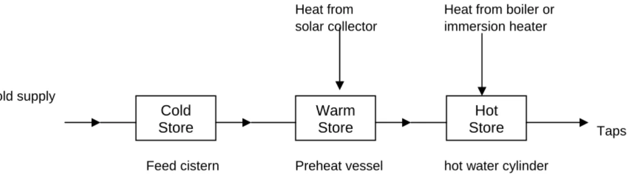
The working principle of solar hot water systems is shown schematically in Figure 5.1. Water from the cold supply is led to the ‘cold store’ (the feed cistern) whence it passes into the preheat vessel, forming the ‘warm store’ where it is heated by solar energy. The water passes then to the ‘hot store’ (the hot water cylinder) which is heated by a boiler or electric immersion heater.
NOTE To discourage the growth of the organism responsible for Legionnaire’s disease, water in the hot store should be kept at a temperature of at least 55 oC.
Heat from Heat from boiler or
solar collector immersion heater
Cold supply
Taps
Feed cistern Preheat vessel hot water cylinder
NOTE Preheat vessel and hot water cylinder may be combined in one vessel
Figure 5.1 – Working principle of solar hot water system 5.2 System types
5.2.1 General
Many different designs of solar water heating systems are possible and they may be classified in several ways. Factors that influence the selection of a specific system type include the amount of water that needs to
Cold Store Warm Store Hot Store
FDUS 853: 2009
be heated, relative cost and efficiency, simplicity of operation, and climate conditions in which the system will be used.
Solar water heating systems are classified into two general categories: - active systems, which use a pump to control water flow, and - passive systems, which use no pump.
Both active and passive systems can be either direct or indirect (Figure 5.2)
- In a direct system, the portable water circulates from the tank to the collector and back to the storage tank. Thus, the heat collecting fluid is the same potable water that is in the water heater.
- In an indirect system, the fluid that circulates through the collector may be water or it may be another heat transfer fluid. This heat-collecting fluid never comes in contact with the potable water in the storage tank. Instead, it transfers heat to the potable water through a heat exchanger.
Figure 5.2 – Direct and indirect solar water heating systems
Further, there are two types of solar water heating systems – active and passive – and each has two categories – direct and indirect.
Active Passive
Direct Direct
Indirect Indirect
Several design variations exist in each system type. The types and variations include: 1. Active direct systems
- Active direct systems that use different types of controllers 2. Active indirect systems
- Active indirect systems that use different types of controllers, heat collecting fluids, and heat exchange mechanisms
3. Passive direct and indirect systems
- Passive direct systems in which the collector and storage are one and the same
5.2.2 Active direct systems
Active direct systems incorporate the following components: - Water storage tank
- Solar collector
- Controller to regulate pump operation
- A pump or circulator to transfer water from the storage tank to the collector
Several additional components ensure proper system operation. Each of these components, listed below and in Figure 5.3, are described in Clause 6.
1) Check valves to prevent thermosiphoning action
2) Isolation valves isolate subsystem components for service. 3) Pressure relief valves relieve high pressure.
4) Temperature and pressure relief valves relieve high temperature and pressures 5) Air vents release air that could cause air locks in the system
6) Vacuum breakers allow proper collector loop drainage
7) Drain valves drain the collector loop and tank or other subsystem components
8) Freeze valves and sensors help to protect the collector from being damaged by freezing temperatures 9) Optional temperature indicators and flow meters monitor components.
FDUS 853: 2009
Active direct systems are principally differentiated by their pump control or freeze protection scheme. Following are descriptions and illustrations of active direct systems based on their method of pump control. 5.2.2.1 Differential controlled
In a differential controlled system (Figure 5.4), the circulating pump operates when sensors located at the top of the collector (hottest point) and bottom of the storage tank (coldest point) indicate a 5-20 oC temperature difference. When the temperature difference drops to about 3 – 5 oC, the pumps switches off. During the course of the day, the controller is constantly comparing the two sensor temperatures. In this way, water circulates through the collector only when sufficient solar energy is available to increase the water temperature.
5.2.2.2 Photovoltaic controlled
The photovoltaic (PV) controlled system (Figure 5.5) uses a PV module to operate pump control functions. In a direct-coupled system, the PV module and pump are sized and matched to ensure that the pump will begin operating when sufficient solar energy for heating water is available and will stop operating when solar energy diminishes.
FDUS 853: 2009
5.2.2.3 Timer - controlled
This control method is used in tropical climates where temperatures are mid year-round and significant amounts of solar energy are available almost everyday. In a timer controlled system (Figure 5.6), a timer turns on a pump in mid morning and switches it off in late afternoon. To ensure that the heated water stratifies at he top of the storage tank, the system uses a very small (≤ 10W) pump. The collector feed and return lines are both connected through the use of a special valve at the bottom of the storage tank so only the coldest water from the tank flows through the solar collector.
Timer controlled systems could conceivably operate during rain or overcast conditions, so care must be taken to ensure the supply and return lines to the collector are located near the bottom of the storage tank. Therefore, if the pump operates during a cloudy day, only a small amount of the water at the very bottom of the tank will be circulated through the collector. This prevents potential major tank heat loss.
5.2.3 Active indirect systems
Indirect systems are typically used in areas of freezing temperatures or areas that have water that is very high in mineral content. The combination of high dissolved minerals and high temperatures produced by the solar system can accelerate scale building in system piping, fittings, and valves.
Like direct system, active indirect systems employ a solar collector, a circulating pump, a potable water storage tank and a variety of ancillary valves. Unlike direct systems, indirect systems also incorporate a heat exchange mechanism that transfers heat from the freeze-proof heat-collecting fluid to the potable water in the storage tank. Active systems are differentiated principally by the type of heat exchanger, controller, and heat collection fluid used.
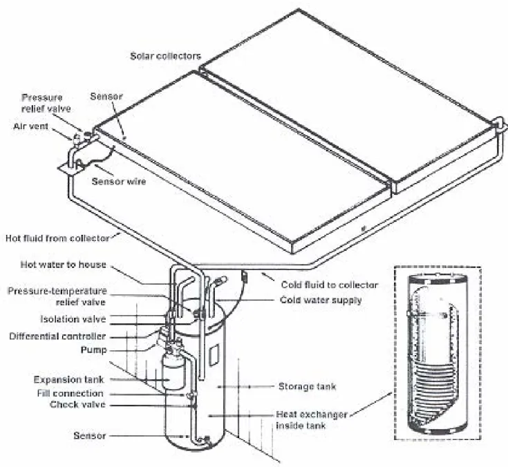
5.2.3.1 Indirect pressurized system
In an indirect pressurized system (Figure 5.7), the heat transfer fluid provides freeze protection at low temperatures. A differential or PV controller activates the circular to move the fluid through the collector. A heat exchanger transfers the heat from the heat transfer medium to the potable water. The heat exchanger may be external to the storage tank, coiled around the outside lower half of the tank, or immersed inside the tank. A double wall heat exchanger is always used in systems that se toxic heat transfer fluids. For systems using non-toxic heat transfer fluids, a single wall heat exchanger is acceptable. An expansion tank on the solar loop compensates for the heat transfer fluid’s expansion and contraction. In addition, these systems require fill and drain valves for adding and servicing heat transfer fluids.
FDUS 853: 2009
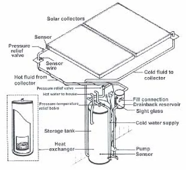
Figure 5.7 – Active indirect system with tank internal heat exchanger 5.2.3.2 Drainback system
Drainback systems offer freeze protection and high-limit protection because the collectors empty by gravity when the system pump is not operating. Since these differentially controlled systems often use distilled water as the heat collection fluid, they offer improved heat transfer to the potable water. When installed correctly, these systems also provide a fail-safe method for protecting the collectors and piping from freeze damage. Each time the differentially controlled pump shuts off, all fluid in the slightly tilted collector and pipes drains into an insulated reservoir tank located in the building’s interior. In some systems, the heat exchanger is incorporated in the drainback reservoir; in others, the heat exchanger may be external or inside the storage tank. This system does not require air vents or vacuum breakers; instead, the piping contains air that should not be added or released.
Drainback systems have a measured amount of air and a measured amount of water in the system. The air is transferred to the reservoir when the pump is running and the water fills the collector. The pump is never without water since water is returning from the collector loop. When the pump shuts off, the air in the reservoir is forced up and into the top of the collector by the water draining back into the reservoir from the bottom of
- Pimps must be sized correctly to overcome gravity and friction losses
- Since the system is not pressurized, expansion tanks, check valves or fill and drain valves are not required
- Collectors and pipe drains must be installed to allow proper and unimpeded drainage back to the drainback reservoir
5.2.4 Passive direct and indirect systems
Passive systems use no pumps or controllers. Instead, they rely on convection either to move water between the collector and storage tank in a thermosiphon system or to stratify heated water within an integral collector system. Most passive systems are direct; that is, the potable water directly collects the sun’s heat in the collector.
When a fluid in the collector is hotter than the water in the preheat vessel, flow occurs by natural convection, transferring heat from the collector to the preheat vessel.
This type of system has the following limitations:
a) The collector has to be sited sufficiently below the preheat vessel to promote natural circulation when the collector is hotter than the store.
b) Freeze protection in the direct gravity system cannot be readily achieved.
c) All pipe work should be of minimal length and of sufficient bore to ensure adequate flow. d) There should be sufficient rise on all pipe runs to prevent air locks.
e) A non-return valve fitted to prevent reverse circulation would need to have a very low pressure drop for forward flow.
Following are descriptions of the most common types of passive systems. 5.2.4.1 Thermosiphon system, direct or indirect
In a thermosiphon system (Figure 5.8) the water storage tank is located above the collector. Cold water from the bottom of the thermosiphon system’s tank flows through a pipe to the bottom of the solar collector. As the sun shines on the collector, the heated water expands slightly and becomes lighter than the cold water. Heavier, denser cold water from the tank flows into the collector inlet, which pushes the lighter, heated water through the collector outlet and up into the top half of the storage tank. This process of displacement provides a tank full of hot water at the end of the day. The solar heated water is drawn from the elevated tank either directly to the hot water service or to an interior auxiliary tank. Some thermosiphon systems (Figure 5.9) include a heat exchanger in or around the tank and an antifreeze solution to avoid freeze problems.
FDUS 853: 2009
Figure 5.8 – Direct thermosiphon system
Figure 5.9 – Indirect thermosiphon system 5.2.4.2 Integral collector storage (ICS) system
In other solar water heating systems the collector and storage tank are separate components. In an integral collector storage system, (Figure 5.10 and 5.11) both collection and solar storage are combined within a
is exposed to solar energy throughout the day. The resulting water is drawn off either directly to the service location or as replacement hot water to an auxiliary storage tank as water is drawn for use.
Figure 5.10 – Integral collector storage (ICS) system
Figure 5.11 – Cutaway of an ICS system 5.2.4.3 Batch system
The simplest of all solar water heating systems is a batch system (Figure 5.12). it is simply one or several storage tanks coated with a black, solar-absorbing material in an enclosure with glazing across the top and insulation around the other sides. It is the simplest solar system to make and is quite poplar with do-it-yourselves. When exposed to direct sun during the day, the tank transfers the heat it absorbs to the water it
FDUS 853: 2009
holds. The heated water can be drawn for service directly from the tank or it can replace hot water that is drawn from an interior tank inside the residence.
Figure 5.12 – Batch solar water heater
5.3 Freeze
protection
Freeze protection mechanisms prevent damage to system components. There are four basic methods used to prevent freezing. These include:
1. Indirect antifreeze fluid circulation 2. Draining
3. Water flow 4. Thermal mass 5. Auxiliary heater
Except for solar systems in the tropics, all systems require some type of freeze protection method. The following examples are some of the more common methods used to prevent freezing. Systems may employ one or more of the following methods of freeze protection.
5.3.1 Indirect antifreeze fluid circulation
Indirect heat exchange systems use a heat-transfer fluid that provides freeze protection in very low temperatures. The antifreeze solution circulates in a closed loop through the collector and heat exchanger. This provides protection to the collector and exterior piping during freezing temperatures.
5.3.2 Draining
Direct systems can be protected from freezing by removing all the water from the collector and the exposed piping. This can be done manually or automatically by one of two methods: drain down or drain back.
loop drainage when power to the electrically operated valve is interrupted. The collectors and piping for these systems must be installed so that no gravity traps or low pots occur so that the collector loop fluid will drain totally by gravity.
Figure 5.13- Drain-down system configuration b) Manual drain-down
Systems can also be designed to be manually drained. The system must have isolation valves between the collector and the storage tank and drain valves on the supply and return lines. The manual draining operation must include shut off of any system controller and circulating pump. It is best to keep he drain valves open when the collectors are drained. A leak or failure of the isolation valve can provide a path for water to flow back to the solar collector and result in freeze damage. Complete draining requires both properly sloped piping and a means for air to enter the system. The use of a vacuum breaker will ensure that the collector loop drains properly. In turn, refilling after draining requires a method to allow air to escape at the high point of the system. A properly installed air vent will provide a means of allowing air to be purged automatically from the system.
c) Drain-back
In drain-back systems (Figure 5.14), a reservoir collects the heat-transfer fluid (usually distilled water) that drains from the collector loop each time the pump turns off. When the pump turns on, it recirculates this same fluid. Generally, a drain back system uses a heat exchanger to transfer heat from the collector fluid to the potable water.
The pump used in these drain-back systems must be capable of overcoming fairly large static heads, since the collector may be mounted several stories above the pump. The pump must be installed in such a way that it is below the low-water mark when liquid is not circulating. As in drain down
FDUS 853: 2009
systems, the collectors and piping for drain back systems must be installed in a way allows no gravity traps or low spots to prevent the drain back of the heat-transfer fluid.
Figure 5.14 – Drain-back system with internal tank heat exchanger Water flow
Freeze prevention may be provided by moving warm from the bottom of the tank through the collector. This movement can be accomplished by recirculation or use of freeze-protection valves.
a) Recirculation
In direct systems, recirculation may be where the threat of freeze damage is infrequent. For recirculation, a freeze sensor is connected to the controller to turn on the pump whenever the collector temperature approaches freezing. For systems that use a separate freeze sensor, the freeze sensor should be placed on the collector plate at the middle or bottom of the collector (away from the collector inlet) so that it will sense the coldest temperature of the collector. Another option is to turn the pump on manually during freeze conditions.
Because the pump requires electric power, this method will fail when a power outage and freeze occur simultaneously. At such a time, the collector must be drained manually.
b) Freeze protection valves
valve to protect the collector and collector loop piping from freezing. Once the valve registers warmer temperatures (from the tank water being circulated through the valve), it closes. This action is repeated throughout the freezing conditions. The valve may be controlled by a spring-loaded thermostat or a bimetallic switch. Figure 5.16 shows where a freeze-protection valve is typically located on a solar DHW system.
Figure 5.15 – Freeze protection valves
Figure 5.16 – Location for freeze protection valve
Freeze-protection valves require water pressure to force water through the valve (and in turn through the collector and associated piping) when activated. If these valves are installed on well water or cistern systems, low-pressure relief valves should also be installed on the system. The valve will open and drain the collector and collector loop when power outages create low pressures.
A check valve shall be used in all systems with freeze-protection valves. They are installed in the collector loop return line (See Figure 5.16). To protect the absorber plate, water must flow through all the pipes. The check valve prevents tank water from flowing straight from the tank to the freeze valve by way of the return line, thus bypassing flow through the collector.
FDUS 853: 2009
5.3.4 Thermal mass
When used in milder climates, integral collector storage and batch type solar systems are protected from freezing by the large thermal mass in their collectors. Nevertheless, special care must be taken to protect exterior and attic collector loop piping. Any thermal mass protected system can eventually lose heat and freeze. The size of the collector tanks, the climatic and geographical location, local winter temperatures, and the length of the freeze all play a factor in determining how effective thermal mass will be as a freeze protection option.
5.3.5 Auxiliary heating
A less commonly used freeze-protection option is to use heat tape or electrical devices that are incorporated in the collector and collector loop piping. During freezing periods, these are activated to provide warmth to the collector and piping. As in recirculation, this relies on the continued availability of electric power during freezes.
6 Components for solar water heating systems
6.1 GeneralThis clause describes the system components and related control functions that are required to collect, transport, store, and convert the solar energy for typical domestic hot water systems. Active systems need controls for pump operation and valves for safety and proper operation. Passive systems utilize many of the same components but in some cases for different reasons. Table 6.1 shows the recommended system components and related control functions that are required for solar hot water systems (see 5.2.2)
Table 1 – Solar water heating system components Component Function
1 Solar collector Convert radiant energy into thermal energy
2 Solar storage tank Accumulate thermal energy in the form of solar heated water to supply domestic needs
3 Insulation Minimize thermal losses from components
4 Piping fittings Interconnect components and convey heat transfer fluid
5 Mixing valve Limit temperature of domestic hot water delivered for personal use 6 Temperature and pressure relief
valve
Automatically relieves pressure if temperature and/or pressure maxima are exceeded
7 Auxiliary heat source Supplements solar energy to provide adequate hot water 8 Pump Circulate liquid
9 Controller Controls the collection and distribution of thermal energy within the solar domestic hot water system and may provide limited safety functions
10 Auxiliary storage tank and heat source
Supplements solar energy to provide hot water and storage 11 Heat exchanger (internal or
external)
Transfer thermal energy between physically separated fluids
12 Air duct Interconnect collectors and heat exchanger in system employing air as transfer medium
13 Blower Circulate air
14 Expansion tank Protect system from pressure damage created by expansion of heat transfer liquid 15 Heat transfer fluid Transports thermal energy
16 Pressure relief valve Automatically relieves pressure if maximum is exceeded 17 Check valve Prevent reverse liquid flow
18 Vent valve Release trapped air
19 Drain valve To drain fluid passages of liquid; manual or automatic
20 Backflow preventer To prevent backflow of nonpotable fluid into potable water supply 21 Vacuum breaker To relieve a vacuum by permitting air into a system
23 Shutoff valves To isolate components, manual or automatic 24 Temperature sensor Senses fluid temperature to operate controller
6.2 Collectors
Solar collectors capture the sun’s electromagnetic energy and convert it to heat energy. While most direct and indirect active systems use flat-plate collectors, some systems employ evacuated tube collectors, or use collectors that incorporate one or more storage tanks.
6.2.1 Flat-plate collectors
Flat plate collectors are designed to heat water to medium temperatures (approximately 60 oC). As shown in Figure 6.1, flat-plate collectors typically include the following components:
a) Enclosure – A box or frame that holds all the components together. The material is chosen for its environmental durability as well as its structural characteristics
b) Glazing – A transparent cover over the enclosure that allows the sun’s rays to pass through the absorber. Most glazing is glass but some designs use clear plastic. In general, the sun’s heat energy passes quite easily through the glazing as short waves. Heat energy that re-radiates from the collector absorber is in long waves. Glass glazing prevents long waves from passing back through the glazing. Glazing also blocks air motion across the absorber, thereby reducing heat loss through convection. The glazing also serves as a transparent insulation that can be single or multiple layers. The more the layers the greater the insulation value, but multiple layers also decrease the amount of light that is transmitted through the layers of glazing.
c) Glazing flame – Attaches the glazing to the enclosure. Glazing gaskets prevent leakage around the glazing frame and allow for contraction and expansion.
d) Insulation – Material between the absorber and the surfaces it touches that blocks heat loss by conduction thereby reducing the heat loss from the collector enclosure. The insulation must be able to withstand extremely high temperatures, so insulations like Styrofoam are not suitable.
e) Absorber - A flat, usually metal surface inside the enclosure that, because of its physical properties, can absorb and transfer high levels of solar energy. The absorber material may be painted black with a semi-selective coating or it may be electroplated or chemically coated with a spectrally selective material (selective surface) that increases its solar absorption capacity by preventing heat from the re-radiating from the absorber.
f) Flow tubes – Highly conductive metal tubes across the absorber through which fluid flows, transferring heat from the absorber to the fluid. The heat transfer fluid tubes remove heat from the absorber. The collector may also incorporate headers, which are the fluid inlet and outlet tubes.
FDUS 853: 2009
Figure 6.1 – Flat plate collector 6.2.2 Evacuated- tube collectors
Evacuated-tube collectors generally have a smaller solar collecting surface because this surface must be encased by an evacuated glass tube. They are designed to deliver higher temperatures (approximately 150 o
C). The tubes themselves comprise of the following elements:
- Highly tempered glass vacuum tubes, which function as both glazing and insulation.
- An absorber surface inside the vacuum tube. The absorber is surrounded by a vacuum that greatly reduces heat losses.
In “flooded” evacuated-tube collectors (Figure 6.2) the absorber itself forms a tube through which the heat collection fluid is pumped. Flooded evacuated-tubes are typically used in passive thermosyphon systems. In a “heat pipe” evacuated-tube collector (Figure 6.3), a flat absorber plate running the length of the tube covers a heat pipe filed with a fluid that evaporates at relatively low temperatures. As the fluid is heated, it evaporates and rises to the top of the tube. There it transfers the heat to water in a manifold. The condensed heat-collection fluid then returns by gravity to the bottom of the heat pipe. These systems can be active or passive.
Figure 6.3 – Heat pipe evacuated –tube collector 6.2.3 Integral collectors
In integral collector storage (ICS) and batch solar water-heating systems, the collector functions as both solar absorber and water storage.
ICS collectors (Figure 6.4) generally incorporate 10 cm or larger diameter horizontal metal tanks connected in series by piping from a water inlet at the bottom of the tank to an outlet at the top. The tanks, which are coated with either a selective or moderately selective absorber finish, are enclosed in a highly insulated box covered with multiple glazing layers. The multiple glazing layers and selective coatings are designed to reduce the heat loss of water stored in the absorber.
Figure 6.4 – ICS collector
The simplest of all water-heating collectors, a batch collector (Figure 6.5) usually is made of just one black – painted metal tank inside an insulated enclosure covered with some type of glazing.
FDUS 853: 2009
Figure 6.5 – Batch collector 6.3 Storage tanks
The storage tank holds the water that has been heated by the collector. The water can be stored in any vessel suitable for high temperatures. The tanks can be pressure rated depending on the application and whether or not a back-up heating system is used.
In subtropical and tropical climates, solar water heating systems usually have a single solar storage tank. This tank usually incorporates an electric heating element. Gas water heaters are not usually for solar storage. The reason for this is that the gas burner is at the bottom of the tank. As cold water enters the tank and activates the gas burner, the whole tank is heated and the gas heat reduces the contribution from the solar system. When gas water heaters are used for back-up, a thermosyphon or ICS system that preheats water entering the gas back-up heater may be used. .A two-tank system may be used where the solar tank preheats the water for the gas back-up tank.
In colder regions and industrial applications, two tanks may be required to store sufficient solar-heated water over very cold or cloudy periods. In these cases a solar storage tank, to which the solar loop is plumped, is connected in a series to an auxiliary water heater or boiler that has “back-up” electric or gas heating. This auxiliary tank or boiler provides hot water in the event there is insufficient solar-heated water. Solar thermal systems that supply heated water for applications other than potable domestic water, such as space heating, may employ more than one storage tank.
The most popular tanks are made of steel with an inner glass, stone or epoxy lining to protect the steel from galvanic corrosion caused by the water’s chemistry. (Dissolved oxygen in the water becomes corrosive to untreated steel). Steel tanks also have an internal aluminium or magnesium “sacrificial” anode rod to attract the oxygen away from the steel. Stone-lined tanks and stainless steel or copper tanks normally do not require anode rods.
Where hard or highly conductive water will be stored in the tank, the anode rod should be replaced periodically. Even in areas with good quality water supplies, the solar storage (an auxiliary) tank should be drained periodically to remove sediment build-up.
corrosion, including ultraviolet degradation, by an ultraviolet (UV) resistant plastic, stainless steel or aluminium jacket. Painted steel or powder coated steel jacket materials on storage tanks require continuous maintenance in coastal or high moisture areas. If the system design requires that tanks be buried below ground, they should have additional insulation and accessible ports for valves and wiring connections. Heat loss from buried storage tanks is accelerated by high water tables or wet ground. Ground conditions should be considered in heat loss calculations.
6.3.1 Single tank systems
The design of conventional water heater tanks encourages mixing water in the tank, producing a tank full of water at the highest selected temperature. For this reason, natural gas and propane system burners are located at the bottom of the tank and conventional electric units have heating elements located in both the top and bottom third of the tank.
6.3.1.1 Electric
Solar systems with single tanks (Figure 6.6) are designed to encourage temperature stratification so that when water is drawn for service, it is supplied from the hottest stratum in the tank (top of tank). For a solar system tank that normally contains a heating element, the element is deliberately located at the upper third of the tank. The electric element functions as back-up when solar energy is not available or when hot water demand exceeds the solar-heated supply. To further encourage stratification of cold and hot water in a storage tank, the cold supply water inlet is located at the bottom of the tank, as is the opening of the collector feed tube. In addition, the collector return tube opens below the heating element, returning the solar heated water to the hottest stratum.
6.3.1.2 Gas
Gas back-up systems may use passive (thermosyphon or ICS) solar preheating plumbed in series for proper operation. Or two separate tanks may be used for active solar systems with gas back-up heating systems. The solar storage tank is piped in series to the auxiliary tank sending the hottest solar preheated water to the gas back-up tank. (See Figures 6.8a and 6.8b).
FDUS 853: 2009
Depending on the system design, solar tanks may be vertical, as shown in Figure 6.6, or horizontal as shown in Figure 6.7. Stratification is generally better in a vertical tank than in a horizontal tank. Yet, aesthetics and mounting considerations favour the horizontal tank design if the tank is mounted on the roof as in a
thermosiphon roof-mounted system.
Figure 6.7 – Horizontal solar storage tank 6.3.2 Multiple – tank systems
In two-tank systems (Figures 6.8a and 6.8b), one tank provides storage for solar-heated water. It is plumbed directly to the solar collector and does not contain any back-up heating source. This solar storage tank is plumbed to a second tank, which contains an auxiliary power source that can be used when no solar energy is available. This type of configuration is most commonly used in residential and light commercial applications. Larger commercial and industrial solar system storage tank strategies can incorporate a single large solar storage tank or multiple smaller solar storage tanks. In these systems, all the tanks are typically plumbed in parallel, thereby acting as a single storage mechanism. The fluid flow is balance so an equal amount of water enters each of the tanks as hot water is drawn for service. These storage tanks supply hot water directly to the back-up (auxiliary) heater or conventional commercial boiler. In certain situations, multiple tank storage systems use parallel piping between most of the tanks and series piping to a single tank with back-up capabilities.
Figure 6.8b – Two –tank solar water heater storage 6.4 Pumps
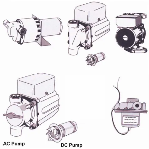
An active system uses a pump or circulator (Figure 6.8a) to move the heat transfer fluid from the storage tank to the collector. In pressurized systems, the system is full of fluid and a circulator is used to move hot water or heat transfer fluid from the collector to the tank. Pumps are sized to overcome static and head pressure requirements in order to meet specific system design and performance flow rates. (It is advisable to refer the pump manufacturer’s pump curve to determine the proper pump size)
Drain-back and other unpressurized solar water heating systems require a high head pump to lift the water from the storage vessel to the collector and force the air out of the collector or collector array. This requires a centrifugal pump or other pump that will provide adequate pressure.
Most active solar systems use centrifugal pumps. Pump selection depends on the following factors: - System type (direct or indirect)
- Heat collection fluid - Operating temperatures - Required fluid flow rates - Friction losses
The most common pump (circulator) used in solar systems is the “wet rotor” type in which the moving part of the pump, the rotor, is surrounded by liquid. The liquid acts as a lubricant during pump operation, negating the need for manual lubrication.
FDUS 853: 2009
Figure 6.10 – Pumps used in solar water heating systems
Pumps used on active direct systems must have bronze or stainless steel housings and impellers to prevent corrosion from water chemistry. Simply put, using cast iron pumps in systems in which the potable water comes into contact with the pump will cause the cast iron to rust. Cast iron pumps can be used with certain heat transfer fluids used in indirect systems. Table 6.1 lists pump options for various applications.
Table 6.1 – Pump applications
Application Pump type and size
Potable water, pressurized, direct active system Bronze or stainless steel, low head Potable water, pressurized, direct active
drain-down system
Bronze or stainless steel, low to medium head
Potable fluids, unpressurized, drain-back Bronze or stainless steel, low to high head Glycol fluids, pressurized Cast iron, low head
Glycol fluids, unpressurized Cast iron, medium to high head
6.5 Piping
Piping provides the path for fluid transport in the system. The piping must be compatible with system temperatures, pressures and other components. Most systems use copper piping because of its durability, resistance to corrosion and ability to withstand very high temperatures. Type L, K or M is commonly used, depending on the application, local codes and traditions.
Copper, brass, and bronze are normally the only materials that should be used in active direct solar systems using potable water. In cases where galvanized piping already exists, it should either be replaced, or dielectric unions should be used to isolate the different metals. (refer to galvanised standard)
When installing-long system piping runs, pipe hangers are commonly used for support. The piping, depending on the type, may be pliable due to high temperatures (temp ranges shud be included) and therefore, must be supported. Since the slope of the piping must be maintained for proper operation and drainage of many systems, pipe hanger are also required to properly orient the pipe runs.
6.5.2 Solder
Solder used in system piping shall comply with ISO 9453, ISO 9454 or ISO 12224 depending on the material to be soldered. Leaded solder should not be used in potable water system piping.
6.5.3 Incompatible materials
Corrosion caused by the contact between dissimilar metals is called galvanic corrosion. Such corrosion usually results in an accelerated rate of attack on only one of several dissimilar metals. In the language of the corrosion expert, the protected material – the one that remains virtually unattached – is called the cathode. The material that is attacked is called the anode.
Metals can be listed in a galvanic series that is useful in predicting which metals are acceptable for use in contact with one another and which materials are likely to be corroded. The following is a simplified galvanic table that can be used as a reference source.
CORRODED END – ANODIC Magnesium
Zinc, Galvanised Steel Aluminium
Mild Steel, cast iron
Lead, Tin
*Brass, Copper, Bronze
*Nickel-Silver, Copper-Nickel Alloys
*Monel
Stainless steel
PROTECTED END – CATHODIC
The coupling of two metals from different groups will result in accelerated corrosion of the metal higher in the series. The farther apart the metals are in the series, the greater the galvanic corrosion tendency. Material groups marked with an asterisk (*) have no strong tendency to produce galvanic action and from a practical standpoint are safe to use in contact with one another.
6.5.4 Pipe insulation
The most common type of pipe insulation used in solar systems is the closed cell flexible elastomeric foam type (rubber)(Figure 6.11). Plastic insulation such as polystyrene or polyethylene should never be used due to their low operating temperatures (Figure 6.12). All exterior piping insulation must be protected from environmental and ultraviolet ray degradation by using special ultraviolet ray resistant coatings, paints or shielded wraps.