http://www.sciencepublishinggroup.com/j/eas doi: 10.11648/j.eas.20180306.11
ISSN: 2575-2022 (Print); ISSN: 2575-1468 (Online)
Study on Optimal Calculation Model for High Piers of Rigid
Frame Bridge Under Pile-Soil Effect
Li Yilin
1, *, Wu Xiaoguang
21
China Road and Bridge Corporation, Beijing, China
2Key Laboratory for Bridge and Tunnel of Shaanxi Province, Chang’an University, Xi’an, China
Email address:
*
Corresponding author
To cite this article:
Li Yilin, Wu Xiaoguang. Study on Optimal Calculation Model for High Piers of Rigid Frame Bridge Under Pile-Soil Effect. Engineering and Applied Sciences. Vol. 3, No. 6, 2018, pp. 134-144. doi: 10.11648/j.eas.20180306.11
Received: November 19, 2018; Accepted: December 4, 2018; Published: January 2, 2019
Abstract:
The relative deformation value measured at the stage of closing and pushing of continuous rigid frame bridge appears difference from the model theoretical calculated values in most cases, because most models ignore the pile-soil effect and simplified consider the bottom of the pier as consolidation. At the same time, most literatures use single pile-soil effect model to analyze the stress influence on bridge structures, however, there are few researches on the difference and simulation accuracy of the different pile-soil effect model. Therefore, this paper discusses the advantages and disadvantages of six different pile-soil effect calculation models, and determining high pier optimal calculation model of rigid frame bridge by comparing and analyzing the relative displacement of the top closure. Last, this article gets the conclusion that the three-spring model is the optimal calculation model of high pier under pile-soil effect.Keywords:
Continuous Rigid Frame Bridge, Pile-Soil Effect, Simulation Accuracy, High Pier, Calculation Models1. Introduction
Continuous rigid frame bridge has been developed rapidly in the long-span bridges of highway in mountainous areas due to its features of economy soundness and construction convenience [1]. Continuous rigid frame bridge is a high-order statically indeterminate structure. When closing the girder during construction, a horizontal thrust is applied to the girder body to make the main pier produce a reverse displacement to offset the secondary internal force caused by temperature difference and later shrinkage creep. In the construction closure of the continuous rigid frame bridge, the author finds that the error between the theoretical displacement and measured displacement is large when the bridge closed and pushed, which is caused by the simulation difference of boundary conditions of pile-soil effect in the calculation model. Because of the complexity and discreteness of the soil, it is rather difficult to study the interaction between foundation and structure. At present, most scholars at home and abroad simplify the pier bottom as consolidation in the analysis and research of the continuous
rigid frame bridge, which cannot fully reflect the interaction between pile and soil in practical engineering. At the same time with the piers getting higher and higher, the stability and dynamic characteristics of high piers have been paid more attention. Therefore, it is necessary to study the selection of reasonable calculation model of high piers under considering the pile-soil effect [2-3].
stiffness and horizontal displacement of continuous rigid frame bridge by combining several different calculation models of pile-soil effect, and proposed that it is necessary to determine reasonable boundary restriction to establish a model close to the actual situation. The literatures mentioned above mostly adopt a single pile-soil effect analysis model to compare and analyze whether pile-soil effect should be taken into account in the common bridge type, and then get the influence analysis of pile-soil effect on seismic response or stress of bridge. However, the difference of the influence of various pile-soil effect analysis models on high piers of continuous rigid frame bridge and the accuracy of the simulation are rarely studied. Therefore, this paper will take a continuous rigid frame bridge as an example, and take the direct consolidation model, equivalent consolidation model, analog bar model, three-spring model, six-spring model and Winkler foundation beam model as six calculation models, to determine the optimal calculation model of the high pier analyzing by comparing the actual measured deformation value and model value of the closure section when closing and pushing the girder, and comprehensively study of the pile-soil effect on high piers of the continuous rigid frame bridge, meanwhile, the advantages and disadvantages of various pile-soil effect analysis model and the simulation
accuracy are discussed.
2. Analysis Model of Pile-Soil Effect
2.1. Direct Consolidation Model
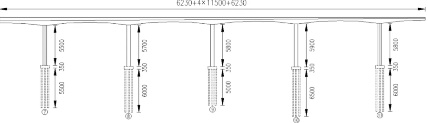
In this paper, the support project is a super-large bridge which located in the Chuankou to Yaozhou highway of 210 national road at Tongchuan city of China's Shaanxi province. The superstructure of the main bridge is a three-dimensional prestressed concrete continuous rigid frame with a combination span of 2×(62.5+4×115+62.5)m, and one united of the whole bridge arrangement is shown in “Figure 1”. In order to facilitate the analysis, the piers are respectively ruled as 7# pier, 8# pier, 9# pier, 10# pier and 11# pier along the direction of the large mileage. The three middle main piers in each part adopt single thin-walled hollow pier, whose section size is 6.5×5.0m with 60cm wall thickness. The two side main piers are double thin-walled hollow pier with section size of 2×6.5×2.49m and wall thickness of 50cm, and 2cm gaps are left between the two limbs and felt or other materials can be filled during construction. The thickness of the main pier bearing platform is 3.5m and the plane size is 12.2×25.7m, and the friction piles of 18Φ170cm are set up under the cap.
Figure 1. Layout drawing of a super-large rigid frame bridge (Unit: cm).
For the continuous rigid frame bridges built in the loess area, the pile-soil effect should be considered in design, construction monitoring and model analysis, and the crux is to accurately simulate the pile-soil interaction effect. It is found that there is a great difference between the displacement calculated by the model and the measured value in the construction monitoring site of the super-large bridge on account of that the finite element model of the bridge is
directly analyzed by the consolidation mode at the bottom of the pier. The stratum of the bridge is mainly composed of Quaternary Holocene alluvial-diluvial, slope-diluvial loess-like soil, alluvial mild clay and pebble, Quaternary Middle Pleistocene aeolian loess, alluvial mild clay, pebble and round gravel. Through in-depth study of pile-soil-structure interaction, the author deems that the pile-soil effect shall be considered on the whole bridge model.
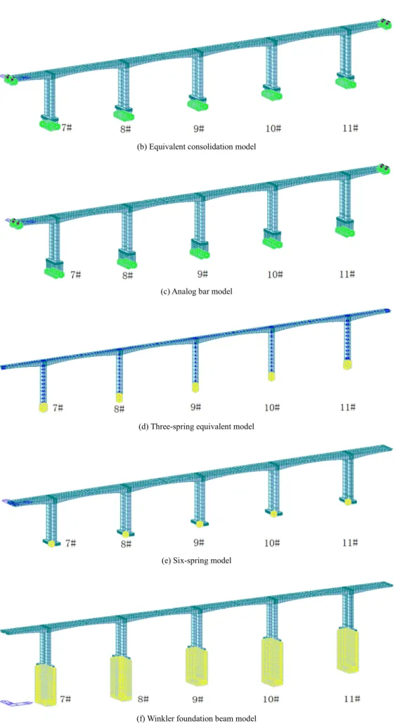
(b) Equivalent consolidation model
(c) Analog bar model
(d) Three-spring equivalent model
(e) Six-spring model
(f) Winkler foundation beam model
The direct consolidation model ignores the influence of pile-soil effect and builds the pier and platform on the rigid foundation. This model is simple in modeling, and the pier bottom and cap top, the cap bottom and rigid foundation are consolidated, which can well reflect the movement of the structure under external load for bridges with hard ground. However, for the bridge on soft ground, some certain limitations exist under this model. In this paper, the finite element software Midas Civil is being used to establish different pile-soil effect models. As the supporting project is a symmetrical double-frame rigid frame bridge, the nodes at the bottom of the bearing platform can be directly consolidated to form a directly embedded model and the specific finite element model is shown in “Figure 2 (a)”.
2.2. Equivalent Consolidation Model
The equivalent consolidation model is to cut off the pile foundation at a certain depth below the ground or the maximum erosion line, and to simplify the pile foundation to a general rigid frame by direct embedding at the cut-off point. The model can better simulate the translational stiffness of pile groups when it is used to simulate the interaction between pile and soil, but the simulation of rotational stiffness is poor, so it is generally applicable to the calculation of large pile groups foundation [10]. The key to establish the equivalent consolidation model is to determine the truncated length of the pile foundation, that is, to determine the embedding depth H.
At present, relevant literatures and specifications [11]have not specified the determination of H, nor a unified theory has
been formed. Many scholars have done a lot of research on it and concluded that the embedded depth is generally 3-5 times of the diameter of the pile according to the principle of equivalent horizontal stiffness of single pile.
According to the equivalent horizontal stiffness equivalence principle of single pile in the calculation of highway bridge pile foundation, the equivalent embedded depth can be determined. The specific calculation formulas are as follows:
3 0 12 HH EI H l ρ
= − (1)
( )0 2 1 1 2
3
2 1 1 2 1
HH
B D B D EI A B A B δ
α
−
= ×
− (2)
1 5mb
EI
α= (3)
Where: EI— The bending stiffness of a single pile. When
the reinforced concrete pile is mainly under bending, it is adopted according to the provisions of [18], and EI=0.8Ec I. Ec is the compressed elastic modulus of the pile body material and I is the gross area inertia moment of a single pile.
α
— The deformation coefficient of pile. If αh> 2.5, thecalculation shall be considered as an elastic pile, otherwise, it shall be calculated as a rigid pile, and where h is the calculated length of pile foundation in soil, m is the proportion coefficient of the foundation soil, b1 is the calculated width of
foundation.
l0— The length of a pile above the scour line or ground line.
( )0
HH
δ — The displacement generated when a single pile top acts on unit horizontal force. ρHH is the horizontal
anti-pushing stiffness of a single pile, and ( )0 1
HH HH
ρ = δ .
The depth of 7#~11# pier from the ground or below the maximum scour line are 55.485m, 61.759m, 52.032m, 67.305m and 60.579m respectively. Because the arrangement form and radius of the pile foundation of these five piers are same, the embedded depth of each pile is consistent according to the formula. According to the above formula, the deformation coefficient of piles can be obtained that
0.396
α = . Because hmin=αzmin=20.6>4, the values of each
coefficient Ai, Bi, Ci, Di (
i
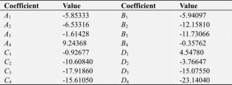
=1, 2, 3, 4) can be obtained according to the specification [11], as shown in “Table 1”.Table 1. Values of each calculation coefficients.
Coefficient Value Coefficient Value
A1 -5.85333 B1 -5.94097
A2 -6.53316 B2 -12.15810
A3 -1.61428 B3 -11.73066
A4 9.24368 B4 -0.35762
C1 -0.92677 D1 4.54780
C2 -10.60840 D2 -3.76647
C3 -17.91860 D3 -15.07550
C4 -15.61050 D4 -23.14040
According to the drawings, the pile foundations of the project are supported by bored piles with low pile cap foundation, and the concrete label is C30. Therefore,
l
0 isequal to 0, and Ec is equal to 3.0×10 7
kN/m2. The pile foundation shape is circular section, and the pile shape conversion coefficient kf is equal to 0.9. The pile foundation layout is multi-row parallel piles, and the net spacing L1 is
equal to 2.8m, and b1 is the calculation width of piles, which is
calculated that b1= ⋅ ⋅ + =k kf
(
d 1)
1.91484m. There is only onesoil layer below the lateral surface or local scour line of the foundation within the scope of hm = 2 (d + 1) = 5.4m, and the main components are round gravel, pebble or gravel. According to the engineering geological survey and specification requirements, the foundation soil ratio coefficient of m is 50000kN/m4, the deformation coefficient of
the pile can be obtained that α= 0.396.
The above values can be substituted into the formula, and the value of H is 7.74m, which is just between 3~5 times of the pile diameter. In order to facilitate calculation and modeling, the embedded depth of the pile foundation H is taken as 8m and the nodes at the bottom of the pile foundation are consolidated to form an equivalent consolidation model. The specific finite element model is shown in “Figure 2 (b)”.
with the calculation analyzed model in “Figure 2 (b)”. Hereinafter referred to as 3D consolidation model, 4D consolidation model, 5D consolidation model and H
consolidation model, and the modeling principles of the four models are the same thus this article will not go into details.
2.3. Analog Bar Model
In the construction of long-span continuous rigid frame bridges in the loess area, the pile foundation is usually longer and the number of piles is more, so it is necessary to consider the interaction effect of pile-soil. If the pile foundation and the superstructure are analyzed and calculated together in the model analysis, the modeling is inconvenient, and the analysis and comparison are not convenient due to the slow calculation speed. Therefore, when calculating the continuous rigid frame bridge, the equivalent principle of the analogue bar method can be used to replace the simple model. Under the action of the horizontal axial force, shear force and bending moment of the pile group foundation at the top of the pile caps, the displacements of the top surface of the cap are equal.
The pile group structure is equivalent to a portal frame by the analogy bar. As shown in “Figure 3”, the bottom of both vertical columns are fixed and the top beam stiffness is infinite.
Figure 3. Schematic diagram of pile group foundation equivalent model.
The displacement symbols on the top of the cap under the action of unit horizontal axial force, shear force and bending moment are defined as follows:
HH
δ , δMH respectively are the horizontal displacement
and rotation angle on the top of the pile when the unit horizontal force (H=1) acts on the original structure; δHM,δMM
respectively are the horizontal displacement and rotation angle on the top of the pile when the unit bending moment (M=1) acts on the original structure, and there are δH M =δM H;
NN
δ is the vertical displacement when the unit vertical force (N=1) acts on the original structure [3].
The equivalent model parameters of the equivalent bar are calculated as follows [13]:
Column height:
2HM
MM
H′ =δδ (4)
Bending moment of inertia:
( )
3
12 2 HH MH
H I
E δ Hδ
′
= ′
− (5)
Cross-sectional area:
2 NN
H A
Eδ
′
′ = (6)
Intermediate distance of column:
( )
2 4
MH
H E I
L
A δ
′ −
=
′ (7)
For the convenience of finite element modeling and calculation, the parameters of the column can be transformed into rectangular section with height is he= 12I A′ and width is be=A h′ e.
The supported project is a low-pile cap foundation with shallow buried depth and loose covering soil, so the elastic resistance of the soil in front of the cap is not considered in the calculation. According to the literature [11], the values of
HM
δ , δHH, δMM are shown in “Table 2”. Thus, the parameters
in the analog bar equivalent model can be obtained:
H’=14.24m, L=7.76m, A’=9.55m2, I=13.30m4. When converted into rectangular section, the parameters in the analog bar equivalent model are as follows: he=4.088m,
be=2.335m, and the analog bar model can be established according to the above calculation parameters, which is as shown in “Figure 2 (c)”.
2.4. Three-Spring Model
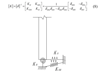
For bridges on loess or soft foundation, the piers are connected by rigidity caps and pile foundations. A double-column rigid frame model can be used to simulate the pier bottom connection, and the restraint effect of pile top under pile-soil interaction is simplified to the restraint effect of pier bottom by restraint spring. As shown in “Figure 4”, in which KH is the translational constraint spring, KM is the
rotational restraint spring, KHM is the flat rotation spring
coupling constraints [3]. In the calculation of the constraint stiffness of pile foundation, the platform is assumed to be rigid, and the flexibility coefficient matrix of the constraint spring in this mode can be obtained, and then the inverse matrix of the flexibility coefficient matrix can be obtained, and the stiffness coefficient matrix is obtained as follows:
[ ] [ ]
1 H MH 1 MM HMHM M MM HH MH HM MH HH
K K K
K K
δ δ
δ− δ δ δ δ δ −δ
= = = −
−
(8)
Figure 4. Constraint stiffness schematic diagram of pile foundation to pier.
K
HK
MThe stiffness of each spring can be obtained by substituting the bringing the coefficient of each pier in the analog bar model into the stiffness coefficient matrix. KMH , KHM
represents the coupling effect between translational and rotational motion of the foundation, which is of equal importance to the translation spring coefficient KH and the
rotational spring coefficient KM, and ignoring the coupling
effect will lead to large errors in the calculation results. However, in the current general finite element analysis program, only translational spring and rotational spring coefficients can be input, but not the coupling spring. The method of dealing with the coupling spring in Midas Civil will be discussed below.
Figure 5. Schematic diagram of three -spring equivalent model.
The pier bottom simulated by three springs is as shown in “Figure 4”, which can be equivalent to the system formed by a massless rigid bar with length of LAB and the end of the rod
can be represented by two translational springs KA and KB.
The equivalent structural stiffness and inertia characteristics are completely equivalent, and the equivalent schematic is shown in “Figure 5”. When the unit horizontal force acts on the top of the pile foundation, the rotation angle and the horizontal displacement at the bottom of the pier are δMH and
HH
δ . If the equivalent model in “Figure 5” also produces the same deformation, the horizontal displacement generated by
the unit horizontal force acting on the base of the equivalent model is δA, as shown in “Figure 6 (a)”, and the rotation angle
is δA LAB. The deformation of the two models will satisfy the
following requirements: δHH=δA, δMH=δA LAB . When the
unit bending moment acts on the top of the pile foundation, the rotation angle at the bottom of the pier is δMM, and the
horizontal displacement is δHM, as shown in “Figure 6 (b)”,
and there are ( ) 2
MM A B LAB
δ = δ +δ and δHM=δA LAB. The above
formula can be obtained that: δA=δHH , LAB=δHH δHM ,
2
B MM LAB A
δ =δ ⋅ −δ .
When the calculated value of LAB is not positive, the
non-gravity rigid rod in “Figure 6” can be applied upward from the bottom of the pier. After obtaining the relevant parameters in the equivalent system, the non-gravity rigid rod can be established in the finite element model, and thus avoiding the input problem of coupling spring in the finite element. The corresponding spring stiffness coefficient with flexibility coefficient are KA =1δA and KB =1δB, and the results are shown in “Table 2”. The unit of δHH is m kN/ ,
and the unit of KA, KB are kN m/ , and the unit of δHM, MH
δ , δMM are rad kN/ , and the unit of LAB is m.
Figure 6. Schematic diagram of equivalent model displacement.
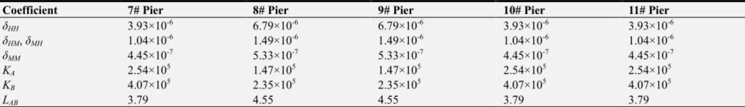
Table 2. Calculation parameter of three-spring equivalent system.
Coefficient 7# Pier 8# Pier 9# Pier 10# Pier 11# Pier
δHH 3.93×10⁻⁶ 6.79×10⁻⁶ 6.79×10⁻⁶ 3.93×10⁻⁶ 3.93×10⁻⁶
δHM, δMH 1.04×10⁻⁶ 1.49×10⁻⁶ 1.49×10⁻⁶ 1.04×10⁻⁶ 1.04×10⁻⁶
δMM 4.45×10⁻⁷ 5.33×10⁻⁷ 5.33×10⁻⁷ 4.45×10⁻⁷ 4.45×10⁻⁷
KA 2.54×10⁵ 1.47×10⁵ 1.47×10⁵ 2.54×10⁵ 2.54×10⁵
KB 4.07×10⁵ 2.35×10⁵ 2.35×10⁵ 4.07×10⁵ 4.07×10⁵
LAB 3.79 4.55 4.55 3.79 3.79
For the three-spring model, since only the pier bottom is constrained, so only the single model is considered when building the model. The specific finite element model is shown in “Figure 2 (d)”.
2.5. Six-Spring Model
The Six-spring stiffness model of pile cap bottom is a common treatment method to simulate the interaction between pile and soil considering the boundary conditions of pile foundation. The six-spring model equates the action of pile
foundation to the constraint spring acting on the bottom of the platform. The pile-soil effect is simulated by the stiffness of the spring in six directions, which respectively are the vertical stiffness, the anti-push stiffness in the direction of longitudinal bridge and transverse bridge, the anti-rotation stiffness around the vertical axis and the anti-rotation stiffness around the two horizontal axes [15]. Because of its clear thinking and simple calculation, it has been widely used in the simulation and calculation of bridge pile foundation. In this paper, the stiffness of these six springs are calculated according to the
K
AL
ABK
BK
BM=1
A
δ
AB
L
B
δ
AB
L
( a ) ( b )
K
AK
BH=1
δA
relevant provisions and formulas in article [11] of P.0.3 and P.0.6.
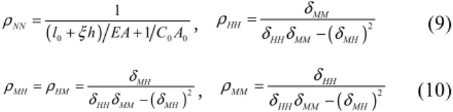
In section 1.4, the flexibility coefficients δHH, δMH, δHM,
MM
δ , δN N of single elastic multi-row piles have been
calculated, and then each stiffness coefficients of single elastic multi-row piles should be calculated. When unit displacement occurs along the axis of the pile, the axial force at the top of the pile is ρNN; and when unit lateral displacement occurs
along the axis of the vertical pile, the horizontal force at the top of the pile is ρHH; and when unit lateral displacement
occurs along the axis of the vertical pile, the bending moment at the top of the pile is ρMH; and when unit angle occurs along
the bending moment of the top of the pile, the bending moment at the top of the pile is ρM M , and the specific
calculation formula is as follows:
(0 ) 0 0
1 1 NN
l h EA C A
ρ
ξ =
+ + , ( )2
MM HH
HH MM MH
δ ρ
δ δ δ
=
− (9)
( )2
MH
MH HM
HH MM MH
δ
ρ ρ
δ δ δ
= =
− , ( )2
HH MM
HH MM MH
δ ρ
δ δ δ
=
− (10)
Bring the stiffness coefficients of each single pile into the formulas, and which are 2
MM NN i i
n K X
ββ
γ = ρ +ρ
∑
, γaa=nρHH,cc n NN
γ = ρ , and the overall stiffness of multi-row piles can be obtained. Where γcc is the sum of the vertical reactions at the
top of the pile when the cap produces the vertical unit
displacement; γaa is the sum of the horizontal reactions at the
top of the pile when the cap produces the horizontal unit displacement; γββ is the sum of the reverse bending moments
at the top of the pile when the cap produces the unit rotation angle; Ki is the number of piles in the i row; and Xi is the
distance from the origin of coordinates to the axis of each pile. According to the above method, γaaxx, γaayy, γcc, γββx and
y
ββ
γ can be calculated, and which respectively correspond to
the x directional horizontal stiffness SDx, the y directional horizontal stiffness SDy, the z directional horizontal stiffness SD z , the x directional angular stiffness SRx, and the y directional angular stiffness SRy. The z directional angular
stiffness SRz is calculated by the formulas and which are ( )
( )0 2 ( )( )0 2
4 4
i i HHx i HHy
M=∑ y δ +x δ , SRz=Mz=
∑
Mi, and where Mi is thevertical angular stiffness of each single pile, Mz is the total
vertical angular stiffness of pile foundation, xi and yi are the
distance between the center of the pile cap section and the center of each pile foundation section along the direction of x
and y.
According to the above calculation method, the spring stiffness of the Six-spring model at the bottom of each cap can be calculated manually, and which are as shown in “Table 3”. The six-spring model is set up through the restrained springs at the bottom of the cap, and the specific finite element model is shown in “Figure 2 (e)”.
Table 3. Spring stiffness values of six-spring model.
Pier 7# Pier 8# Pier 9# Pier 10# Pier 11# Pier
SDx 3971344 2298232 2298232 3971344 3971344
SDy 1985672 1149116 1149116 1985672 1985672
SDz 5775265 5306493 6334883 4908108 5306493
SRx 1058404149 969493800 1151711692 904754784 975343697
SRy 251447922 229537728 271187532 216328068 232462676
SRz 292691209 169381486 169381486 292691209 292691209
2.6. Winkler Foundation Beam Model
Winkler foundation beam model simulates piles as beams placed in soil, and uses distributed springs and dampers to simulate the effect of soil around piles act on the pile foundation. This method has been widely used because of its clear concept and accurate simulation of the pile-soil interaction effect [16]. The "m method" recommended in literature [11] is a simplified Winkler foundation beam model. The basic principle of "m method" is to treat the pile as an elastic foundation beam, and to solve it according to Winkler hypothesis, that is, the soil resistance at any point of the beam body is proportional to the displacement at that point. The calculation formula of equivalent soil spring stiffness after model transformation is as follows:
1
1
s zx
s z
z z z
P A ab
k mzx ab C
x x x
σ
= = = ⋅ = σzx=mzxz (11)
Where: σzx is the transverse resistance of soil to pile; z is
the depth of soil layer; xz is the transverse displacement of
pile at the depth of z; a is the thickness of each soil layer; C is
the foundation reaction coefficient, and for non-rock soil, the foundation reaction coefficient varies linearly with depth in "m method", that is C=mz , for rock foundation, the foundation reaction coefficient is C=C0. According to the geological conditions of different piers, the soil layers are divided into different layers and thickness. The stiffness of equivalent soil springs of each pile foundation is calculated according to the above formulas. The Winkler foundation beam model is established for each pile at the bottom of the bearing platform through the constraint spring. The concrete finite element model is shown in “Figure 2 (d)”.
3. Effect Analysis of Different
Calculation Models on the Horizontal
Displacement of the Closure Jacking
is adopted in the one-time closure scheme. When closing, the mid-span and the sub-middle span first pushed the horizontal force of 20t, and then increasing the jacking force by 10t in turn according to the displacement monitoring of the closure section. In order to facilitate the analysis of the results, this paper selects the top thrust of 20%, 60% and 100%, that is, the horizontal force of 300kN, 900kN and 1500kN is applied to the middle-span respectively, and the horizontal force of 500kN, 1500kN and 2500kN is applied to the two sub-middle span. In order to analyze the influence of different calculation models on the horizontal displacement of the closure thrust, the displacement deformation values of the closure section of different calculation models when the jacking force
respectively are 20%, 60% and 100% are shown in “Table 4”, in which A, B, C, D, E, F, G are used to replace the dates of Direct Consolidation Model, Equivalent Consolidation Model, Analog Bar Model, Three-spring Model, Six-spring Model, Winkler Model and Measured Data respectively and 1, 2, 3, 4, 5, 6 are used to replace the first span, the second span, the third span, the fourth span, the fifth span and the sixth span respectively. When the top thrust is 100%, the displacement values of the 3D consolidation model, 4D consolidation model, 5D consolidation model and H consolidation model are shown in in “Table 5”. The comparison of the six calculation models and the measured relative deformation results of the closed sections at different jacking stages are shown in “Figure 7”.
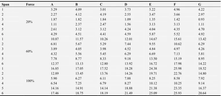
Table 4. Joint sections’ deformations of the different calculation models at construction jacking force under different construction jacking force (unit: cm).
Span Force A B C D E F G
1
20%
3.29 4.09 3.01 3.73 5.22 4.96 4.22
2 2.27 4.12 4.19 2.55 3.47 3.66 2.97
3 1.87 1.82 1.84 1.09 1.35 1.42 0.93
4 1.11 2.37 2.47 1.56 3.13 3.13 1.11
5 2.61 3.12 3.12 4.24 4.04 4.35 4.70
6 4.29 4.51 4.41 4.59 5.87 5.52 4.92
1
60%
10.87 11.57 10.26 12.01 14.67 15.61 13.42
2 6.81 5.67 5.29 7.44 9.55 10.62 6.29
3 3.89 4.05 3.98 4.52 4.84 4.97 4.26
4 4.32 5.56 5.45 6.29 6.69 7.13 5.81
5 7.78 8.77 8.33 9.18 13.50 15.19 8.95
6 12.37 13.13 12.80 13.92 16.72 17.98 14.22
1
100%
16.85 17.05 17.52 18.28 24.38 25.98 18.52
2 12.89 13.45 13.76 14.26 19.71 22.76 14.80
3 5.90 6.27 6.11 7.88 8.25 8.58 7.92
4 6.54 7.25 6.79 8.27 10.12 10.25 9.14
5 14.16 14.91 14.14 18.88 21.38 23.35 16.37
6 17.46 18.75 18.19 21.49 25.09 25.93 20.64
Table 5. Joint sections’ deformations of the different consolidation calculation models at construction jacking force of 100% (unit: cm).
Jacking Force 100% 3D 4D H 5D
First Span 16.95 17.02 17.05 17.08
Second Span 12.89 13.12 13.45 13.46
Third Span 5.96 6.05 6.27 6.38
Fourth Span 7.03 7.18 7.25 7.27
Fifth Span 14.33 14.65 14.91 14.98
Sixth Span 17.96 18.22 18.75 18.89
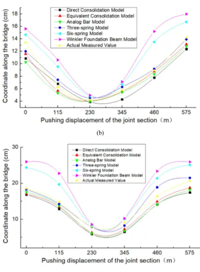
(b)
(c)
Figure 7. Joint sections’ deformations of the different calculation models at construction jacking force of 20%(a), 60%(b), 100%(c).
By analyzing the results of “Table 4”, “Table 5” and “Figure 7”, we can draw the following conclusions:
(1) Whatever the calculation model, the relative deformation of the closure segment is in order from large to small when multiple points are used to push the closure at one time. The sequence is as follows: side span closure section, secondary side span closure section and middle span closure section. Because the two largest cantilever ends of 9# pier are balanced push, the relative deformation of the middle span closure section is the smallest. For pier 7# and 11# pier, the side span has no top thrust, and only the secondary side span acts as non-equilibrium top thrust, so the relative deformation of the side span closure section is the largest. The top thrust of the middle span and the second middle span acting on both sides of the 8# pier and the 10# pier respectively, but the top thrust acting relatively is not as large as the non-equilibrium top thrust mentioned above, so the relative deformation of the closing section of the secondary side span is in the center.
(2) For these six calculation models, the overall trend of relative deformation of the same closure under the same working condition is increasing gradually as follows: direct consolidation model, equivalent consolidation model, analog bar model, three-spring model, six-spring model and Winkler foundation beam model. The influence of pile-soil effect considered by each model is increasing gradually.
(3) The relative deformation values of the closed segments at different pushing stages calculated by direct consolidation model, equivalent consolidation model, analog bar model are close to each other, for example, when the thrust is 100%, the error ranges of actual measured data and displacement of the fourth span closure section are 28.5%, 20.7% and 25.7% respectively. It can be concluded that the pile-soil effect considered by these three models is not obvious.
(4) From the thrust displacement of the four equivalent consolidation model in “Table 5”, it can be seen that the pile-soil effect is gradually increasing with the increase of the equivalent embedded depth, but compared with the other calculation models, the pile-soil effect considered by the equivalent consolidation model is not obvious, and the embedded depth of the equivalent consolidation model can be conveniently and quickly taken as 3 to 5 times of the diameter of the pile.
pile number is more and the structure is more complex, considering the convenience of modeling, the six-spring model can be used instead of the Winkler foundation beam model for simplifying calculation.
(6) From the trend distribution of the calculation results of each model in “Figure 7”, it can be seen that the overall distribution and trend of the three-spring model are the closest to the measured data. When the top thrust is 100%, the maximum error of the calculation results is only 15.3%, which is much smaller than that of other models. Meanwhile, from the convenience of modeling and the practicability of considering pile-soil effect analysis, it can be concluded that the three-spring model is the optimal selection model for the calculation model of high pier under pile-soil effect.
4. Conclusion
In this paper, taking a continuous rigid frame bridge as an example, comparing the displacement and model values of the closed section measured during the closure push to determine the optimal calculation model for the high pier of the continuous rigid frame bridge under the pile-soil effect from six different calculating models of pile-soil effect. At the same time, the advantages and disadvantages of various pile-soil effect analysis models and their simulation accuracy are compared. The detailed conclusions are as follows: the influence of pile-soil effect considered by each calculation model is gradually increased according to direct consolidation model, equivalent consolidation model, analog bar model, three-spring model, six-spring model and Winkler foundation beam model; The pile-soil effect considered in the first three calculation models is not obvious, and the embedded depth of the equivalent consolidation model can be taken as 3 to 5 times of the diameter of the pile; and for the large pile group foundation, the six-spring model can be used instead of the Winkler foundation beam model for simplified calculation. In view of the convenience of modeling and the practicability of considering pile-soil effect analysis, the three-spring model is the optimal calculation model of high pier under pile-soil effect.
Acknowledgements
This paper is completed under the meticulous guidance of Professor Wu Xiaoguang, my graduate tutor Mr. Wu has poured a lot of effort during the whole process of paper compilation from subject section, data collection as well as finalization, for which I desire to express my heartfelt appreciation to my tutor with great excitement. Meanwhile, I would like to appreciate my parents who give me thoughtful kindness, constant understanding, support and encouragement, which renders me great spiritual strength and is the source of motivation for my research and progress. Also I would like to thank my girlfriend and say to my dear, “Please Marry Me”. This study was conducted on the basis of the work of the predecessors them plenty of
theories and the research results of scholars related to this paper have been cited for complete this paper, with deep appreciation for them.
References
[1] Li Yi-lin, Yang Xiu-rong, Liu Ying. Linear Relationship Between Height-span Ratio Parameters of Continuous Rigid Frame Bridge [J]. Journal of Henan University of Urban Construction, 2016, 25 (6): 26-30.
[2] Wu Xiao-guang, Li Yi-lin, He Qi-long, FENG Yu. Analysis for Transverse Vibration Frequencies of Large Span Continuous Rigid Frame Bridge with High Piers Based on Frequency Synthesis Method [J]. Journal of Inner Mongolia University (Natural Science Edition), 2017, 48 (02): 213-218.
[3] Wu Xiao-guang, Li Yi-lin, He Pan, QIAN Ruo-lin. Stability Analysis of High Piers and Large Span Continuous Rigid Frame Bridge Based on Energy Method [J]. Journal of Railway Science and Engineering, 2017, 14 (02): 290-295.
[4] Syed NM, Maheshwari K. Non-linear SSI Analysis in Time Domain Using Coupled FEM-SBFEM for a Soil-pile System [J]. Geotechnique, 2017, 67 (7): 572-580.
[5] Li Feng-lan, Zhang Shi-min, Liu Shi-ming. Effect of Pile-soil Action on Seismic Resistance of Prestressed Continuous Box-girder Bridge with Changed Sections [J]. Applied Mechanics and Materials, 2012, 238 (4): 743-747.
[6] Jiang Bo-jun, Xian Qiao-ling, Zhou Fu-lin. The Influence Analysis of the Effect of Pile-soil Contact on the Seismic Response of the High Speed Railway Bridge [J]. Journal of Guangzhou University (Natural Science Edition), 2016, 15 (1): 57-63.
[7] Yang Mei-liang, Li Zhen-hua, Zhong Yang. Influence of Pile-soil effect on Continuous Rigid Frame Composite Beam Bridge With Short Pier [J]. China and Foreign Highway, 2012, 32 (5): 112-115.
[8] Zhang Xu-lin, Xiao Guang-qing. Influence of Pile-soil effect on Continuous Rigid Frame Bridge With Short Pier [J]. Hunan Communication Science and Technology, 2016, 42 (2): 140-142+146.
[9] Chen Cong-chun, Xiong Fei. The Comparative Study of Continuous Rigid Frame Bridge Longitudinal Incremental Launching Stiffness [J]. Highway Engineering, 2016, 41 (1): 163-166+187.
[10] Zhou Min, Yuan Wan-cheng, Zhang Yue. Parameter Sensitivity Analysis of Equivalent Anchorage Length for Elevated Pile Caps [J]. Journal of Chang’an University (Natural Science Edition), 2010, 30 (3): 47-52.
[11] JTG D63-2007, Code for Design of Ground Base and Foundation of Highway Bridges and Culverts [S]. Beijing: People's Communications Press, 2007.
[12] Lin Zhi-sheng. Influence of Pile-soil effect on Mechanical Behavior With Short Pier of Continuous Rigid Frame Bridge [J]. China Water Transport, 2008 (11): 180-181.
[14] Hu Duan-qian. Dynamic Characteristics of High Pier Bridge with Variable Cross-section in Mountainous Expressway [D]. Changsha: Central South University, 2007.
[15] Zhang Yu. Seismic Response of a Single-tower Cable-stayed Bridge with Dynamic Soli-structure Interaction [D]. Chengdu: Southwest Jiaotong University, 2015.
[16] Huang Sen-hua. Elastic-plastic Seismic Response Analysis OF High Pier and Long Span Curve Rigid Frame-CONTINUOUS Combination Bridge [D]. Xi’an: Chang’an University, 2014.
[17] Yin Ren-hong, An Ping-he, Feng Wei-qiong. Closure Order of Multiple-span Continuous Rigid Frame Bridge [J]. Journal of Shenyang University (Natural Science), 2017, 29 (1): 58-61. [18] JTG D62-2012, Coad for Design of Highway Reinforced