PRODUCT ... 2
1 MODELS LIST ... 2
1.1 Outdoor Unit ... 2
1.2 Indoor Unit ... 3
2 NOMENCLATURE ... 4
3 FUNCTION ... 4
4 PRODUCT DATA ... 5
4.1 Product Data at Rated Condition ... 6
4.2 Operation Range ... 19
4.3 Electrical Data ... 20
5 PIPING DIAGRAM ... 21
CONTROL ... 23
1 OPERATION FLOWCHART ... 23
1.1 Cooling/Dry Operation ... 23
1.2 Heating Operation ... 24
2 MAIN LOGIC ... 25
2.1 Cooling ... 25
2.2 Dry Mode ... 26
2.3 Heating Mode ... 27
2.4 Defrosting ... 28
2.5 Fan Mode ... 29
3 WIRELESS REMOTE CONTROLLER ... 30
3.1 Operation View ... 30
3.2 Display View ... 32
4 WIRED REMOTE CONTROLLER ... 33
4.1 Operation View ... 33
4.2 Display View ... 35
4.3 Dimension ... 36
4.4 Installation ... 36
5 CENTRALIZED CONTROLLER ... 38
5.1 Centralized Controller-not with week timer ... 38
5.2 Centralized Controller-week timer ... 39
5.3 Field Setting ... 43
5.4 Control Wiring Design ... 44
INSTALLATION ... 46
1 INDOOR UNIT INSTALLATION ... 46
1.1 Installation of Duct Type ... 46
1.2 Installation of Ceiling Type ... 55
2.3 Caution for Installation ... 71
2.4 Dimension Data ... 72
2.5 Installation Clearance Data ... 73
3 REFRIGERATION PIPING WORK ... 74
3.1 Refrigeration Piping Work Procedures ... 74
3.2 Caution in Connecting Pipes ... 77
3.3 Specification of Connection Pipe ... 78
4 ELECTRIC WIRING WORK ... 79
4.1 Wiring Principle ... 79
4.2 Electric Wiring Design ... 83
4.3 Specification of Power Supply Wire and Air Switch ... 86
MAINTENANCE ... 89
1 TROUBLE TABLE ... 89
2 FLOW CHART OF TROUBLESHOOTING ... 93
3 WIRING DIADRAM ... 103
3.1 Wiring Diagram-Outdoor Units ... 103
3.2 Wiring Diagram-Indoor units ... 111
4 DISASSEMBLY AND ASSEMBLY PROCEDURE OF MAIN PARTS_ ... 113
4.1 Outdoor Unit ... 113
4.2 Indoor Unit ... 141
5 EXPLODED VIEWS AND PART LIST ... 160
5.1 Outdoor Unit ... 160
PRODUCT
1 MODELS LIST
1.1 Outdoor Unit
Model
Nominal Capacity Cooling/Heating
(Btu/h)
Ref. Power Supply ULS-09 8870/9720 R410a 220-240̚,1,50 ULS-12 11940/12283 R410a 220-240̚,1,50 ULS-18 17060/19448 R410a 220-240̚,1,50 ULS-24 23884/27296 R410a 220-240̚,1,50 ULS-36 33437/37532 R410a 220-240̚,1,50 ULT-36 34120/37532 R410a 380-415̚,3,50 ULT-45 40944/47768 R410a 380-415̚,3,50 ULT-50 47768/52886 R410a 380-415̚,3,50 ULT-60 54592/63122 R410a 380-415̚,3,50
1.2 Indoor Unit
Type Model
Nominal Capacity Cooling/Heating
(Btu/h)
Ref. Power Supply Duct Type IDI-09 8870/9720 R410a 220-240̚ 1Ph 50Hz IDI-12 11940/12283 IDI-18 17060/19448 IDI-24 23880/27300 IDI-36 33437/37500 IDI-45 42000/48000 IDI-50 48000/53000 IDI-60 60000/63120 Floor- Ceiling Type IKI-09 8870/9720 R410a 220-240̚ 1Ph 50Hz IKI-12 11940/12283 IKI-18 17060/19448 IKI-24 23880/27300 IKI-36 33437/36781 IKI-45 42000/48000 IKI-50 48000/53000 Cassette Type ICI-12 11940/12283 R410a 220-240̚ 1Ph 50Hz ICI-18 17060/19448 ICI-24 23201/25590 ICI-36 36000/37500 ICI-45 42000/48000 ICI-50 48000/53000
Note:1 Ton =12000Btu/h = 3.517kW
NOTES˖The universal outdoor unit means that the customer can choose any of three kind of indoor unit to
match the outdoor unit without any change with it.
2 NOMENCLATURE
NO. Description Options
1 INVENTOR
2 Unit Type
U=Match Outdoor Unit F=Duct Type
K=Cassette Type T= Ceiling Type 3 Product Type C=Cool Only
H=Heat Pump without Aux Electric Heaters
4 Power Supply Code
N=Constant Frequency D=DC Inverter A=AC Inverter
5 Nominal Cooling Capacity Nominal Cooling Capacity =Number×1000Btu/h 6 Climate Type N=Climate T1 Condition
T= Climate T3 Condition 7 Power Supply Code K=1Ph 220~240V 50HZ
M=3Ph 380~415V 50HZ
8 Refrigerant 1 =R22 2=R407C 3=R410A
9 Design Code Design Code:A,B,C,D…… 10 Unit Code for Condensing Unit
or Indoor Unit
O=Outdoor I=Indoor Unit
Function Description
Memory function when unit restart after power off, it will run on former status, the mode and parameter are kept the same
Remote control function wireless controller and remote controller can be opted, and the maximum control distance of remote controller is 10m.
Timing function it can timing ON/ OFF separately, meanwhile, it can also can timing on circularly
Self-diagnosis with alarm function once unit has malfunction, the malfunction code will be indicated and alarm ring immediately
Sleep function it can self control for saving energy in energy saving mode.
Automatic function the fan of indoor unit can adjust fan speed automatically based on actual demand when cooling or heating under automatic mode
Cool air proof function the fan starts only when the temperature of indoor unit heat exchanger is higher than indoor temperature under heating mode
Weekly Timer
Centralized Control and Week Timer Functions: The centralized controller and the weekly timer are integrated in the same wire controller. The system has both the centralized control and the week timing functions. Up to 16 sets of units can be controlled simultaneously by the centralized controller (weekly timer). The weekly timer has the function of invalidating the lower unit. The weekly timing function is able to realized four timing ON/OFF periods for any unit every day, so as to achieve fully automatic operation. No timing control can be set for holidays.
High/low pressure protection when suction pressure is too low or discharge pressure is too high, compressor will stop and unit display malfunction code
Overload protection
compressor has its own overheat protection, once the temperature of compressor is higher than allowable level, compressor will stop and only when temperature recovery, compressor restart
Over current protection once the current of compressor is higher that normal level, compressor will stop and unit display malfunction code
Discharge high temperature protection
once the discharge temperature of compressor is higher than allowable value, compressor will stop and unit display malfunction code
Reverse (open) phase protection once the phase sequence of power supply is incongruent or the phase is absent, unit can’t work and display malfunction code
Anti-high
temperature protection
once the heat exchanger temperature of indoor unit is too high, compressor stop and unit display malfunction code.
Timing ON/OFF display display and timing turn ON/OFF time Fan speed display display the speed (high, medium, low) of fan
Function model display cooling mode, dehumidifying mode, heating mode, fan mode Testing display display testing mode
4.1 Product Data at Rated Condition
4.1.1 Duct Type
Model
Indoor unit IDI-09 IDI-12 IDI-18
Outdoor unit ULS-09 ULS-12 ULS-18
Nominal Capacity
Cooling
kW 2.6 3.5 5.0
Btu/h 8870 11940 17060
Heating
kW 2.85 3.6 5.7
Btu/h 9720 12283 19448
Power Input
Cooling kW 1.35 1.2 2.1
Heating kW 1.4 1.1 1.8
EER/COP W/W 2.6/2.94 2.92/3.55 2.38/3.22
Indoor Unit IDI-09 IDI-12 IDI-18
Power Supply ˉ 220-240V~/1 Ph/50HZ
Heat Exchange ˉ Cross Fin Coil
Fan
Type ˉ Centrifugal fan
Drive ˉ Direct Driver
Motor Output kW 0.02×2 0.02×2 0.07×2
Air Flow m3/h 550 600 840
Ext. Static Pressure Pa 25 25 40
Sound Pressure Level˄H/M/L˅ dB(A) 37 / 36 /34 40/38/36 42/40/38 Air Filter ˉ Standard washable synthetic
Drain Piping mm 20×1.2 20×1.2 30×1.5
Dimensions (H×W×D)
(Outline/Package) mm
220×913×680/ 258×995×750 220×913×680/ 258×995×750 266×1012×736 308×1120×795
Weight˄Net/Gross˅ kg 27/32 27/32 36/39
Outdoor Unit ULS-09 ULS-12 ULS-18
Power Supply ˉ 220-240V~/1Ph/50HZ
Heat Exchange ˉ Cross Fin Coil
Fan
Type Axial fan
Motor Output kW 0.03 0.03 0.03
Fan Motor Speed rpm 850
Compressor Type ˉ ROTARY
Motor Output kW 0.922 1.185 1.9
Refrigerant
Type ˉ R410A
Control ˉ Capillary Tube
Charge kg 1.1 1.0 1.5
Dimensions (H×W×D)
(Outline/Package) mm
540×848×320/ 590×878×360 540×848×320/ 590×878×360 540×848×320/ 590×878×360
Weight˄Net/Gross˅ kg 32/37 32/37 40/45
Piping Connections
Liquid mm 6.35 6.35 6.35
Outdoor unit ULS-24 ULS-36 ULS-36
Nominal Capacity
Cooling
kW 7.0 9.8 10
Btu/h 23880 33437 36000
Heating
kW 8.0 11 11
Btu/h 27300 37500 37500
Power Input
Cooling kW 2.66 4.0 4.0
Heating kW 2.51 3.5 3.5
EER/COP W/W 2.63/3.19 2.5/3.14 2.5/3.14
Indoor Unit IDI-24 IDI-36 IDI-36
Power Supply ˉ 220-240V~/1 Ph/50HZ
Heat Exchange ˉ Cross Fin Coil
Fan
Type ˉ Centrifugal fan
Drive ˉ Direct Driver
Motor Output kW 0.15×2 0.5×2 0.5×2
Air Flow m3/h 1400 2000 2000
Ext. Static Pressure Pa 80 150 150
Sound Pressure Level˄H/M/L˅ dB(A
) 44 / 42 /40
50 / 48 /46
50 / 48 /46 Air Filter ˉ Standard washable synthetic
Drain Piping mm 20×1.2 20×1.2 20×1.2
Dimensions (W×H×D)
(Outline/Package) mm
1270 ×268×504/ 1345×268×594
1251×290×744/ 1335× 290× 834
1251×290×744/ 1335× 290× 834
Weight˄Net/Gross˅ kg 37/45 57/67 57/67
Outdoor Unit ULS-24 ULT-36 ULS-36 Power Supply ˉ 220-240V~/1Ph/50
HZ
380-415V~/3Ph/50 HZ
220-240V~/1Ph/50 HZ
Heat Exchange ˉ Cross Fin Coil
Fan
Type Axial fan
Motor Output kW 0.068×1 0.092×2 0.092×2
Fan Motor
Speed(H/M/L) rpm 840/620/400 940/840/700 940/840/700 Compress
or
Type ˉ ROTARY SCROLL SCROLL
Motor Output kW 2.475 3.65 3.8
Refrigeran t
Type ˉ R410A
Control ˉ Capillary Tube
Charge kg 2.2 3.2 3.2
Dimensions (W×H×D)
(Outline/Package) mm
1018×700× 412/ 1100 ×755× 450
1018 ×8 40×412/ 1110 × 985 × 450
1018 ×8 40×412/ 1110 ×985 × 450
Weight˄Net/Gross˅ kg 59/64 90/100 90/100
Piping Connectio
ns
Liquid mm 9.52 12.7 12.7
Gas mm 15.8 19.05 19.05
Max. Height
Difference m 15 30 30
Continued
:2 ModelIndoor unit IDI-45 IDI-50 IDI-60
Outdoor unit ULT-45 ULS-48N ULS-60
Nominal Capacity
Cooling kW 12 14 16
Btu/h 42000 48000 60000
Heating kW 14 15.5 18.5
Btu/h 48000 53000 63120
Power Input
Cooling kW 5.3 5.8 6.5
Heating kW 4.9 5.4 5.5
EER/COP W/W 2.26/2.86 2.41/2.87 2.46/3.27
Indoor Unit IDI-45 IDI-50 IDI-60
Power Supply ˉ 220-240V~/1 Ph/50HZ
Heat Exchange ˉ Cross Fin Coil
Fan
Type ˉ Centrifugal fan
Drive ˉ Direct Driver
Motor Output kW 0.5×2
Air Flow m3/h 2000 2300 2500
Ext. Static Pressure Pa 150 150 150
Sound Pressure Level˄H/M/L˅ dB(A) 50 / 48 /46 50 / 48 /46 53 / 50 /48 Air Filter ˉ Standard washable synthetic
Drain Piping mm 20×1.2 20×1.2 32×1.5
Dimensions (W×H×D)
(Outline/Package) mm
1251× 290 ×744/ 1335 × 290× 834
1251×290×744/ 1335× 290× 834
1251×330×788/ 1334 ×330 × 882
Weight˄Net/Gross˅ kg 57/67 57/67 66/76
Outdoor Unit ULT-45 ULT-50 ULT-60
Power Supply ˉ 380-415V~/3 Ph/50HZ
Heat Exchange ˉ Cross Fin Coil
Fan
Type Axial fan
Motor Output kW 0.092×2
Fan Motor Speed(H/M/L) rpm 940/840/700 940/840/700 940/840/700
Compressor Type ˉ SCROLL
Motor Output kW 4.75 4.5 5.75
Refrigerant
Type ˉ R410A
Control ˉ Capillary Tube
Charge kg 3.55 3.8 5.0
Dimensions (W×H×D)
(Outline/Package) mm
1018×700× 412 /1100 ×755×450 950×1250×412 /1110×1385×450 950×1250×412 /1110×1385×450
Max. Length m 50
Max. Height Difference m 30
Note˖
ķ Nominal capacities are based on the follow conditions.
Indoor
Outdoor
Cooling DB
˖
27
ć
(80.6
̧
)
WB
˖
19
ć
(66.2
̧
)
DB
˖
35
ć
(95
̧
)
WB
˖
24
ć
(75.2
̧
)
Heating DB
˖
20
ć
(68
̧
)
WB
˖
--
ć
(--
̧
)
DB
˖
7
ć
(44.6
̧
)
WB
˖
6
ć
(42.8
̧
)
Piping Length
5mĸ
The air volume is measured at the relevant standard external static pressure.
Ĺ
Noise is tested in the Semi anechoic Room, so it should be slightly higher in the actual
operation due to environmental change.
4.1.2 Ceiling Type
Models Indoor unit IKI-09 IKI-12 IKI-18
Outdoor unit ULS-09 ULS-12 ULS-18
Nominal Capacity
Cooling kW 2.6 3.5 5.0
Btu/h 8870 11940 17060
Heating kW 2.85 3.6 5.7
Btu/h 9720 12280 19448
Power Input
Cooling kW 1 1.17 2.03
Heating kW 1 1.1 2.07
EER/ COP W/W 2.6/2.85 2.99/3.55 2.46/2.8
Indoor Unit IKI-09 IKI-12 IKI-18
Power Supply ˉ 220-240V~/1 Ph/50HZ
Heat Exchange ˉ Cross Fin Coil
Fan
Type ˉ Centrifugal fan
Drive ˉ Direct Driver
Motor Output kW 0.01×2 0.01×2 0.04×2
Air Flow m3/h 550 550 700
Sound Pressure Level˄H/M/L˅ dB(A) 47/44/41 46/44/41 54/50/46 Air Filter ˉ Standard washable synthetic
Drain Piping mm 28×1.5
Dimensions (W×H×D)
(Outline/Package) mm
836×238×695/ 935×295×805 836×238×695/ 935×295×805 836×238×695/ 935×295×805
Weight˄Net/Gross˅ kg 27/35.5 27/35.5 32/36
Outdoor Unit ULS-09 ULS-12 ULS-18
Power Supply ˉ 220-240V~/1 Ph/50HZ
Heat Exchange ˉ Cross Fin Coil
Fan
Type Axial fan
Motor Output kW 0.03 0.03 0.03
Fan Motor Speed rpm 850 850 850
Compressor Type ˉ ROTARY
Motor Output kW 0.922 1.185 1.9
Refrigerant
Type ˉ R410A
Control ˉ Capillary Tube
Charge kg 1.1 1.0 1.5
Dimensions (W×H×D)
(Outline/Package) mm
848×540×320 /878×590×360 848×540×320 /878×590×360 848×540×320 /878×590×360
Weight˄Net/Gross˅ kg 32/37 32/37 40/45
Piping
Max. Height Difference m 15 15 15
Continued
1 ModelsIndoor unit IKI-24 IKI-36 IKI-36
Outdoor unit ULS-24 ULT-36 ULS-24
Nominal Capacity
Cooling kW 7.0 9.8 10
Btu/h 23880 33440 36000
Heating kW 8.0 10.78 11
Btu/h 27300 36780 37500
Power Input
Cooling kW 2.61 3.6 3.6
Heating kW 2.59 3.3 3.3
EER/ COP W/W 2.68/3.09 2.78/3.33 2.78/3.33
Indoor Unit IKI-24 IKI-36 IKI-36
Power Supply ˉ 220-240V~/1Ph/50HZ
Heat Exchange ˉ Cross Fin Coil
Fan
Type ˉ Centrifugal fan
Drive ˉ Direct Driver
Motor Output kW 0.1×4 0.085×2 0.085×2
Air Flow m3/h 1170 1800 1800
Sound Pressure Level˄H/M/L˅ dB(A
) 50/48/46 54/51/48
54/51/48
Air Filter ˉ Standard washable synthetic
Drain Piping mm 28×1.5
Dimensions (H×W×D)
(Outline/Package) mm
1300×188×600 /1414×248×724 1590×238×695/ 1714×330×830 1590×238×695/ 1714×330× 830
Weight˄Net/Gross˅ kg 32/36 42/51 42/51
Outdoor Unit ULS-24 ULT-36 ULS-24 Power Supply ˉ 220-240V~/1Ph/50
HZ
380-415V~/3Ph/50 HZ
220-240V~/1Ph/50 HZ
Heat Exchange ˉ Cross Fin Coil
Fan
Type ˉ Axial fan
Motor Output kW 0.068 0.092×2 0.092×2
Fan
MotorSpeed(H/M/L )
rpm 840/620/400 940/840/700
940/840/700
Compressor Type ˉ ROTARY SCROLL SCROLL
Motor Output kW 2.475 3.65 3.8
Refrigerant
Type ˉ R410A
Control ˉ Capillary Tube
Charge kg 2.2 3.2 3.2
Dimensions (W×H×D)
(Outline/Package) mm
1018 ×700×412/ 1100×755×450 1018×840×412/ 1110×985×450 1018×840×412/ 1110×985×450
Weight˄Net/Gross˅ kg 59/64 90/100 90/100
Piping Connections
Liquid mm 9.52 12.7 12.7
Gas mm 15.8 19.05 19.05
Max. Length m 30 50 50
Max. Height
Difference m 15 30
30
Continued
2Models Indoor unit IKI-45 IKI-50
Outdoor unit ULT-45 ULT-50
Nominal Capacity
Cooling kW 12 14
Btu/h 42000 48000
Heating kW 14 15.5
Btu/h 48000 53000
Power Input
Cooling kW 4.8 6.1
Heating kW 4.7 5.8
EER/ COP W/W 2.5/2.98 2.3/2.67
Indoor Unit IKI-45 IKI-50
Power Supply ˉ 220-240V~/1Ph/50HZ
Heat Exchange ˉ Cross Fin Coil
Fan
Type ˉ Centrifugal fan
Drive ˉ Direct Driver
Motor Output kW 0.085×2 0.18×2
Air Flow m3/h 1800 2100
Sound Pressure Level˄H/M/L˅ dB(A) 54/51/48 58/55/52 Air Filter ˉ Standard washable synthetic
Drain Piping mm 28×1.5
Dimensions (W×H×D)
(Outline/Package) mm
1590×238×695 1714×330×830
1590×238×695/ 1714×330×830
Weight˄Net/Gross˅ kg 42/51 42/51
Outdoor Unit ULT-45 ULT-50
Power Supply ˉ 380-415V~/3 Ph/50HZ
Heat Exchange ˉ Cross Fin Coil
Fan
Type Axial fan
Motor Output kW 0.092×2 0.092×2
Fan MotorSpeed(H/M/L) rpm 940/840/700 940/840/700
Compressor Type ˉ SCROLL
Motor Output kW 4ˊ75 4.5
Refrigerant
Type ˉ R410A
Dimensions (W×H×D)
(Outline/Package) mm
950×1250×412/ 1110 ×1385× 450
950×1250×412/ 1110 ×1385× 450
Weight˄Net/Gross˅ kg 112/123
Piping Connections
Liquid mm 12.7
Gas mm 19.05
Max. Length m 50
Max. Height Difference m 30
Note˖
ķ Nominal capacities are based on the follow conditions.
Indoor
Outdoor
Cooling
DB
˖
27
ć
(80.6
̧
)
WB
˖
19
ć
(66.2
̧
)
DB
˖
35
ć
(95
̧
)
WB
˖
24
ć
(75.2
̧
)
Heating
DB
˖
20
ć
(68
̧
)
WB
˖
--
ć
(--
̧
)
DB
˖
7
ć
(44.6
̧
)
WB
˖
6
ć
(42.8
̧
)
Piping Length
5mĸ The air volume is measured at the relevant standard external static pressure.
Ĺ Noise is tested in the Semianechoic Room, so it should be slightly higher in the actual operation due to environmental change.
4.1.3 Cassette Type
Models Indoor unit ICI-12 ICI-18
ICI-24
Outdoor unit ULS-12 ULS-18 ULS-24
Nominal Capacity
Cooling kW 3.5 5.0
6.8
Btu/h 11940 17060 23200
Heating kW 3.6 5.7
7.5
Btu/h 12280 19450 25590
Power Input
Cooling kW 1.17 2.0 2.62
Heating kW 1.1 1.9 2.5
EER/COP W/W 2.8/3.2 2.5/3.05 2.67/3.2
Indoor Unit ICI-12 ICI-18 ICI-24
Power Supply ˉ 220-240V~/1 Ph/50HZ
Heat Exchange ˉ Cross Fin Coil
Fan
Type ˉ Centrifugal fan
Drive ˉ Direct Driver
Motor Output kW 0.011 0.011 0.035
Air Flow m3/h 550 600 1180
Sound Pressure Level˄H/M/L˅ dB(A) 47/45/43 Air Filter ˉ Standard washable synthetic
Drain Piping mm 31×3 31×3 32×3
Indoor Unit Dimensions
(Outline/Package) (W×H×D) mm
600×230×600/ 848×310×678 600×230×600/ 848×310×678 840×260×840/ 960×310×960 Panel Dimensions
(Outline/Package) (H×W×D) mm
50×650×650/ 102×730×670 50×650×650/ 102×730×670 60×950×950/ 115×1040×1025 Weight˄Net/Gross˅ kg 20/27 20/27 30 / 38
Outdoor Unit ULS-12 ULS-18 ULS-24
Power Supply ˉ 220-240V~/1 Ph/50HZ
Heat Exchange ˉ Cross Fin Coil
Fan
Type Axial fan
Motor Output kW 0.03 0.03 0.068
Fan Motor Speed(H/M/L) rpm 850 850 840/620/400
Compressor Type ˉ ROTARY
Motor Output kW 1.185 1.9 2.475
Refrigerant
Type ˉ R410A
Dimensions (W×H×D)
(Outline/Package) mm
848×540×320/ 878×590×360
848×540×320/ 878×590×360
1018×700×412/ 1100×755×450
Weight˄Net/Gross˅ kg 32/37 40/45 59/64
Piping Connections
Liquid mm 6.35 6.35 9.52
Gas mm 12.7 12.7 15.8
Max. Length m 20 20 30
Continued
1Models Indoor unit ICI-36 ICI-36
Outdoor unit ULT-36 ULS-36
Nominal Capacity
Cooling kW 10 10
Btu/h 36000 36000
Heating kW 11 11
Btu/h 37500 37500
Power Input
Cooling kW 3.6 3.6
Heating kW 3.1 3.3
EER/COP W/W 2.78/3.55 2.78/3.33
Indoor Unit ICI-36 ICI-36
Power Supply ˉ 220-240V~/1 Ph/50HZ
Heat Exchange ˉ Cross Fin Coil
Fan
Type ˉ Centrifugal fan
Drive ˉ Direct Driver
Motor Output kW 0.06
Air Flow m3/h 1600 1800
Sound Pressure Level˄H/M/L˅ dB(A) 53/51 /48 Air Filter ˉ Standard washable synthetic
Drain Piping mm 32×3
Indoor Unit Dimensions
(Outline/Package) (W×H×D) mm
840×320×840/ 960×394×960 Panel Dimensions
(Outline/Package) (H×W×D) mm
60×950×950/ 115×1040×1025
Weight˄Net/Gross˅ kg 38/46
Outdoor Unit ULT-36 ULS-36
Power Supply ˉ 380-415V~/3Ph/50HZ 220-240V~/1Ph/50HZ
Heat Exchange ˉ Cross Fin Coil
Fan
Type Axial fan
Motor Output kW 0.092×2
Fan Motor Speed(H/M/L) rpm 940/840/700
Compressor Type ˉ SCROLL
Motor Output kW 3.65 3.8
Refrigerant
Type ˉ R410A
Control ˉ Capillary Tube
Charge kg 3.2
Dimensions (W×H×D)
(Outline/Package) mm
1018× 840 ×412 1110 ×985×450
Weight˄Net/Gross˅ kg 90/100
Piping Connections
Liquid mm 12.7
Gas mm 19.05
Max. Length m 50
Continued
2Models Indoor unit ICI-45 ICI-50
Outdoor unit ULT-45 ULT-50
Nominal Capacity
Cooling kW 12 14
Btu/h 42000 48000
Heating kW 14 15.5
Btu/h 48000 53000
Power Input
Cooling kW 4.8 5.8
Heating kW 5.0 6.2
EER/COP W/W 2.5/2.8 2.3/2.67
Indoor Unit ICI-45 ICI-50
Power Supply ˉ 220-240V~/1 Ph/50HZ
Heat Exchange ˉ Cross Fin Coil
Fan
Type ˉ Centrifugal fan
Drive ˉ Direct Driver
Motor Output kW 0.06
Air Flow m3/h 1650 1700
Sound Pressure Level˄H/M/L˅ dB(A) 53/ 51 /48 Air Filter ˉ Standard washable synthetic
Drain Piping mm 32×3
Indoor Unit Dimensions
(Outline/Package) (H×W×D) mm
840×320×840/ 960×394×960 Panel Dimensions
(Outline/Package) (H×W×D) mm
60×950×950/ 115×1040×1025
Weight˄Net/Gross˅ kg 38/46
Outdoor Unit ULT-45 ULT-50
Power Supply ˉ 380-415V~/3 Ph/50HZ
Heat Exchange ˉ Cross Fin Coil
Fan
Type Axial fan
Motor Output kW 0.092×2
Fan Motor Speed(H/M/L) rpm 940/840/700
Compressor Type ˉ SCROLL
Motor Output kW 4.75 4.5
Refrigerant
Type ˉ R410A
Control ˉ Capillary Tube
Charge kg 3.55 3.8
Dimensions (W×H×D)
(Outline/Package) mm
950×1250×412/ 1110 × 1385 ×450
Weight˄Net/Gross˅ kg 112/123
Piping Connections
Liquid mm 12.7
Gas mm 19.05
Max. Length m 50
Note˖
ķ Nominal capacities are based on the follow conditions.
Indoor
Outdoor
Cooling DB
˖
27
ć
(80.6
̧
)
WB
˖
19
ć
(66.2
̧
)
DB
˖
35
ć
(95
̧
)
WB
˖
24
ć
(75.2
̧
)
Heating DB
˖
20
ć
(68
̧
)
WB
˖
--
ć
(--
̧
)
DB
˖
7
ć
(44.6
̧
)
WB
˖
6
ć
(42.8
̧
)
Piping Length
5mĸ The air volume is measured at the relevant standard external static pressure.
Ĺ Noise is tested in the Semianechoic room, so it should be slightly higher in the actual operation due to environmental change.
4.2 Operation Range
Mode Range
of
Outdoor
Temperature
ć
(
̧
)
Cooling 18
ć
-43
ć
-7
ć
-43
ć
(with low Ambient kit)
Heating -7
ć
-24
ć
4.3 Electrical Data
Model
Compressor Fan Motor
Max. Fuse Breaker Size (Indoor/Outdoor) Min. Disconnect Size (Indoor/Outoor) Power
Supply Qty. LRA RLA
Condenser Fan Motors
Supply Blower Motor V,Ph,Hz ˉ Each Each FLA
Each
FLA
Each Amperes Amperes ULS-09
IDI-09
220-240 1 50
1 18 4.28 0.27
0.18 6/10 1/5.7
IDI-09 0.09 6/10 1/5.7
ULS-12
IDI-12
1 32 5.6 0.27
0.18 6/13 1/7.3
IKI-12 0.09 6/13 1/7.3
ICI-12 0.1 6/13 1/7.3
ULS-18
ICI-18
1 40 8.8 0.27
0.63 6/20 1.5/11.3
ICI-18 0.36 6/20 1/11.3
ICI-18 0.1 6/20 1/11.3
ULS-24
ICI-24
1 60 11.2 0.61
1.35 6/25 2.5/14.6
ICI-24 0.9 6/25 1.5/14.6
ICI-24 0.32 6/25 1/14.6
ULS-36
ICI-36
1 97 18.42 0.8
4.5 10/40 5.7/23.8
ICI-36 1.35 6/40 2.5/23.8
ICI-36 0.54 6/40 1/23.8
ULT-36
ICI-36
380-415~ 3 50
1 67 6.58 0.8
4.5 10/16 5.7/9.1
ICI-36 1.35 6/16 2.5/9.1
ICI-36 0.54 6/16 1/9.1
ULT-45
ICI-45
1 66 8.22 0.8
4.5 10/20 5.7/11.1
ICI-45 1.35 6/20 2.5/11.1
ICI-45 0.54 6/20 1/11.1
ULT-50
ICI-50
1 59.4 8 0.8
4.5 10/16 5.7/10.8
ICI-50 1.62 6/16 2.5/10.8
ICI-50 0.54 6/16 1/10.8
ULT-60 ICI-60 1 67 9.77 0.8 4.5 10/20 5.7/13
Notes˖
RLA˖Rated load amperes LRA˖Locked rotor amperes FLA˖Full load current
CONTROL
1 OPERATION FLOWCHART
2 MAIN LOGIC
2.1 Cooling
OFF ON
OFF
ON
OFF OFF
OFF OFF
OFF H
When T
amb.T
preset t+1
ć
, the unit begins cooling operation and the compressor and the outdoor
fan are running; and the indoor fan is running at a set speed.
When T
amb.tTpreset-1
ć
, the unit is in the cooling shutdown state, and the compressor and the
outdoor fan stop running; and the indoor fan is running at a set speed.
When T
preset-1
ć˘
T
amb.˘
T
preset+1
ć
, the unit keeps in the operation state.
Cooling mode
Compressor
Outdoor fan
Indoor fan
4-way valve
Manual shutdown
Starting up
Operation at a set speed
Time
H grade2.2 Dry Mode
OFF ON
OFF ON
OFF OFF
OFF OFF
OFF H
When T
amb.T
preset+2
ć
, the unit begins cooling operation and the compressor and the outdoor fan
are running; and the indoor fan is running at a low speed.
When T
amb.T
preset-2
ć
, the unit is in the cooling shutdown state and the compressor and the
outdoor fan stop running.
When T
prese-2
ć˘
T
amb.˘
T
preset+2
ć
, the unit is in the six-minute stop and four-minute operation
state, that is, the compressor runs for 6 minutes and then stops for 4 minutes, in such cycle
repeatedly; and the indoor fan operates at a low speed.
Compressor
Outdoor fan
Indoor fan
4-way valve
Dry Mode
Manual shutdown
Starting up
Operation at a low speed H grade
2.3 Heating Mode
OFF ON
OFF ON
OFF OFF
OFF OFF
ON
ON
OFF OFF
OFF
OFF ON
When T
amb.T
preset-1
ć
, the unit begins heating operation and the compressor and the outdoor fan
are running; and the indoor fan is running at a set speed according to cold fan prevention
conditions.
When T
amb.T
preset+1
ć
, the compressor and the outdoor fan stop running and the four-way valve
keeps energized; and the indoor fan is running according to afterheat blowing conditions.
When T
䇮-1
ć˘
T
amb.˘
T
preset+1
ć
, the unit keeps in the previous operation state.
Compressor
Outdoor fan
Indoor fan
4-way valve
Heating Mode
Manual shutdown
Starting up
Auxiliary heating
Operation at a set speed
Operation under normal conditions Operation in blowing
afterheat state
Cold blast prevention
2.4 Defrosting
ON
ON
OFF
ON
OFF
OFF OFF ON
ON ON
ON
ON ON
Defrosting start conditions: after the heating operation runs for an accumulated period of 44
minutes and the compressor continues to operate for 4 hours and 50 seconds, and a one-minute
duration of T
cond.-5
ć
is detected, the unit begins defrosting. If an auxiliary heater is available, it
must be stopped firstly, and after 10 seconds, the four-way valve, the indoor fan, the outdoor fan
and the compressor will run compulsively.
Defrosting completion conditions: when defrosting runs 10 minutes or T
cond.10
ć
, defrosting will
be completed. In such case, the four-way valve is running, the outdoor fan is running, the
compressor is running compulsively, and the indoor fan operates according to cooling fan proof
conditions.
Compressor
Outdoor fan
Indoor fan
4-way valve
Auxiliary heating
Defrosting
Enter thedefrosting mode
Withdraw the defrosting mode
Operation at a set speed
Operation under normal conditions
Cold blast prevention
2.5 Fan Mode
OFF
OFF
OFF
OFF
OFF
OFF
H
The indoor fan runs at a fast speed for 5s and then runs at a set speed.
Compressor
Outdoor fan
Indoor fan
4-way valve
Fan Mode
Time
Manual shutdown
Starting up
Operation at a set speed H grade
3 WIRELESS REMOTE CONTROLLER
3.1 Operation View
(1) Controller-Duct Type
212)) 02'(
$872)$1
6:,1* $872 6:,1*
23(5 $,5
)$1
NO. Name Function description
1 ON/OFF button Press the button to set start or close unit
2 Mode button
Press the button to select the mode, cooling , heating , fan or auto mode.
3 Increase/Decrease button Press this button to increase/decrase the setup temp 4 LCD Screen Display the status of remote information
5 Swing button Press this button set swing function 6 Fan speed button Press this button to set fan speed
(2)Controller-Cassette Type and Ceiling Type
212)) 02'( /,*+7 $872 7,0(5 212)) 6:,1* +80,' 6:,1* $XWR)DQ 6$9( +5 $,5 )$1 23(5 7,0(5 212)) 212)) $1,21 7,0(2)) 7,0(21 02'( /,*+7 6/((3 6$9( +80,' $,5 +5 /,*+7 $872)$1 6:,1* +80,' $872 6:,1* 6$9( 23(5 $,5 )$1NO. Name Function description
1 Swing button Press this button to set swing function
2 Increase/Decrease button Press this button to increase/decrase the setup temp
3 Mode button
Press the button to select the mode, cooling , heating , fan or auto mode. 4 ON/OFF button Press the button to set start or close unit 5 LCD Screen Display the status of remote information 6 Fan speed button Press this button to set fan speed 7 Sleep button Press the button to set sleep function 8 Time on Press the button to set time on function 9 Time off Press the button to set time off function
3.2 Display View
/,*+7 $872
7,0(5 212)) 6:,1* +80,'
6:,1*
$872)$1
6$9( +5 $,5
)$1
23(5
No. Display Function description
1 Fan Speed
˖auto fan speed, ˖low fan speed, ˖middle fan speed ˖high fan speedˈ
2 Run Mode
˖Auto running˗ ˖Cool running˗ ˖Dry Running˗ ˖Fan Running˗
˖Heat running (Heat and Cool unit only) 3 Setup temp Temperature value of setting
4 Swing function Swing is on 5 Sleep mode Sleep mode is on 6 Time value Timing value of setting 7 OPER The controller is on
4 WIRED REMOTE CONTROLLER
4.1 Operation View
˄
1
˅
Wired Controller-Duct Type
MODE
ON/OFF
FAN
SLEEP
TIMER
˄
2
˅
Wired Controller-Cassette Type and Ceiling Type
MODE
ON/OFF FAN
SWING
NO. Name Function description 1 MODE button
Press the button to select the mode, cooling , heating , fan or auto mode. 2 Increasing button Press this button to increase the setup temp. 3 Decreasing button Press this button to decrase the setup temp. 4 Fan speed button Press this button to set fan speed
5 Sleep/SWING button Press the button to set sleep/swing function 6 Timer button Press the button to set timer function 7 On/off button Press the button to set start or close unit 8 Remote window Get remote information
9 LCD display Display unit information
Note˖
˄1˅ SAVE set up ˖At unit turned off, to press the “FAN” +“” buttons continuously 5 seconds, it can come enter save set up interphase, the unit will run at save mode.
˄2˅ FRESH valve setup : At unit is turned off, press the “ FAN” button for 5seconds,And set up the fresh air setup.
˄3˅ Outer ambient temperature display: Under normal condition, “ENV” will display the room ambient temperature, at unit turned on, or unit turned off status, press “SLEEP/SWING” button last for 5 seconds, the LCD will display “OUT ENV”.
˄4˅ MEMORY function setup: At unit turned off, press “MODE” button for 10 seconds, could switch whether turn on or off the unit state after powered off.
˄5˅ Debugging function: At unit off, continuously press “FAN” + “SLEEP” buttons lasting for 10seconds, call out debugging menu, and displays “Debugging” icons, use “MODE” button adjust setting item, by pressing “”, “” button to set up the detailed value.
(A) Ambient sensor set up: it can set three kinds styles.
˄6˅ Lock function: Press “”and“” at the same time for 5 seconds, the set temp. will display “EE” and shield, all buttons will sound; and repress the“”and “”at the same time for 5 seconds, the lock function will be released.
4.2 Display View
MODE
ON/OFF
FAN
SWINGTIMER
NO. Name Function description
1 Timer value Display time value 2 Timer on/off
˖display timer onˈ :display timer offˈ
3 Fan speed display
˖auto fan speedˈ ˖low fan speedˈ
˖middle fan speedˈ ˖high fan speed 4 Set temp display Display set temp valueˈits range is 16~30
5 Run mode display
˖auto modeˈ ˖cool modeˈ ˖dry modeˈ ˖fresh fan modeˈ ˖fan modeˈ
˖heat mode(only cool and heat unit) 6 Indoor temp display Display surrounding temp indoor
7 Outdoor temp display Display surrounding temp outdoor 8 Frost display When unit frosts ,it display 9 Sleep display Display sleep at Sleep mode
4.3 Dimension
4.4 Installation
1.
First select an installation position. According to the size of the communication line of the
wire controller, leave a recess or a embedded wire hole to bury the communication line.
2.
If the communication line between the wire controller (85×85×20) and the indoor unit is
surface-mounted, use 1# PVC pipe and make matching recess in the wall (refer to Figure 6);
If concealed installation is adopted, 1# PVC pipe can be used (Refer to Figure 7).
3.
No matter if surface mounting or concealed mounting is selected, it is required to drill 2 holes
(in the same level) which distance shall be the same as the distance (60mm) of installation
holes in the bottom plate of the wire controller. Then insert a wood plug into each hole. Fix
the bottom plate of the wire controller to the wall by using the two holes. Plug the
communication line onto the control panel. Lastly install the panel of the wire controller.
Caution:
During the installation of the bottom plate of the wire controller, pay attention to the direction
of the bottom plate. The plate’s side with two notches must be at the lower position, and otherwise
the panel of the wire controller cannot be correctly installed.
39&SLSH
Fig6˖Surface Mounting of Cable Fig7˖Concealed mounting of Cable
Fig 8 Schematic Diagram of Installation
No. Name
1 Wall
Surface
2
Bottom Plate of Wire Controller
3 Screw
M4X10
4
Panel of Wire Controller
Caution:
1.
The communication distance between the main board and the wire controller can be as far as
20m (The standard distance is 8m).
2.
The wire controller shall not be installed in a place where there is water drop or large amount
of water vapor.
5 CENTRALIZED CONTROLLER
5.1 Centralized Controller-not with week timer
5.1.1 Function
Centralized Controller-not with week timer only control on-off function of every units. Up to 16 sets of units can be controlled simultaneously by the centralized controller-not with week timer.
5.1.2 Operation View
NO. Name Function description
1 ON button Press the button to set start unit 2 OFF button Press the button to set close unit 3 LCD display Display unit information
4 LED LED indication
5 Increasing / Decreasing button Press buttons select the unit
5.1.3 Display View
5.1.4 Dimensions
5.2 Centralized Controller-week timer
5.2.1 Function
Centralized Control and Week Timer Functions: The centralized controller and the weekly timer
are integrated in the same wire controller. The system has both the centralized control and the
week timing functions. Up to 16 sets of units can be controlled simultaneously by the centralized
controller (weekly timer). The weekly timer has the function of invalidating the lower unit. The
weekly timing function is able to realized four timing ON/OFF periods for any unit every day, so
as to achieve fully automatic operation. No timing control can be set for holidays. On and off of
every duct type unit can be done through the Timer On / Off of this WEEKLY TIMER
ˈ
it can not
set other functions except on-off function of units.
5.2.2 Operation View
NO. Name Function description
1 ENTER button when “enter” is pressed the setting is validate.
2 Increasing button
Press “” and selected the unit or a certain day in one week or specific value. Press “” can set week part of time.
3 Decreasing button Press “ ” and selected the unit or a certain day in one week or specific value. Press “ ” can set week part of time.
4
CANCEL/DELETE button
short-press “cancel/delete” to back to default page or last process, long-press “cancel/delete” to cancel timer of a certain time period in a certain day
5
SINGLLE/GROUP button
short-press “single/group” to enter single control setting. “SINGLE” displayed. long-press “single/group” to enter group control setting. “GROUP” displayed
6
TIMER/TIME button
Short-press “timer/time” to enter timer setting.
Long-press “timer/time” under default page can begin time setting. 7 On/off button Control unit run or stop
5.2.3 Display View
NO. Name Function description
1 unit’s no. displays Display unit’s numbers
2 Group control displays when group controls, it will display 3 Single control displays when single unit controls, it will display 4 Timer time in week displays Display time in week
5 Timer displays Display time 6 timer state displays
“on”: when set unit on, “on” will display; “off”: when set unit off, “off” will display; 7 timer on time displays Display starts time
8 on control displays When set unit or group on, it will display, 9 off control displays When set unit or group off, it will display, 10 present time in week display Display present time of week.
11 present time in Hr:Min displays Display time of hour and minute now 12 timer off time displays Display over time
13 timer period displays Set to different time segment
Note
5.3 Field Setting
The centralized controller displays code of various units: unit code is determined by the
position (on the back of the manual operator) of the toggle switch of the manual operator on each
flue pipe air conditioner. Toggling values are corresponding to the 4-1 feet from the right to left of
the toggle switch. “ON” stands for “0”, and conversely, “OFF” stands for “1”
Example 1: to get “0111”, which represents the serial number “8”, you can put foot 1, 2 and 3
of the toggle switch to the opposite of “ON” and foot 4 to “ON”.
Example 2: to get “1010”, which represents the serial number “11”, you can put foot 2 and 4
of the toggle switch to the opposite of “ON” and foot 1 and 3 to “ON”.
Position Serial No. Position Serial No. Position Serial No. Position Serial No.
0000 1 0100 5 1000 9 1100 13
0001 2 0101 6 1001 10 1101 14
0010 3 0110 7 1010 11 1110 15
0011 4 0111 8 1011 12 1111 16
As shown in the following diagram:
ᵪ㓴㕆⸱
ᵪ㓴㕆⸱
ᵪ㓴㕆⸱
ᵪ㓴㕆⸱
ᵪ㓴㕆⸱
ᵪ㓴㕆⸱
ᵪ㓴㕆⸱
ᵪ㓴㕆⸱
ᵪ㓴㕆⸱
ᵪ㓴㕆⸱
ᵪ㓴㕆⸱
ᵪ㓴㕆⸱
ᵪ㓴㕆⸱
ᵪ㓴㕆⸱
ᵪ㓴㕆⸱
ᵪ㓴㕆⸱
Unit code:1
Unit code:2
Unit code:3
Unit code:4
Unit code:5
Unit code:6
Unit code:7
Unit code:8
Unit code:9
Unit code:10
Unit code:11
Unit code:12
5.4 Control Wiring Design
16 Units in Max
Week timer
Wired remote controllerLCD
LCD
LC
Wired remote controlle
Telephone wire box Telephone wire box Telephone wire box
Twisted-wire with crystal joint
Longest distance 1200m
Corresponding relation between code switch and sequence of unit (Note:Putting code switch to ON means 0.)
AC-LAC-N Power supply
P S P S P S P
S
0000 1 0010 5 0001 9 0011
13
1000 2 1010 6 1001 10 1011
14
0100 3 0110 7 0101 11 0111
15
INSTALLATION
1 INDOOR UNIT INSTALLATION
1.1 Installation of Duct Type 1.1.1 Before Installation
When the unit arrives, please check if any damage due to transport is existent. If any hurt is found on the surface or inside, please declare to the transport company or the manufacturer in writing.
Upon receipt of the unit, the unit and accessories shall be checked in accordance with the packing list. Before acceptance, it must be confirmed that the model is correct and the unit is in good shape and specification and quantity of accessories are right.
Correct handling route and method shall be decided to prevent damage to the unit. For protecting the unit and ensuring its safety, carrying the unit with its package is recommended. If such carrying method is difficult under particular conditions, the canton shall not be removed to avoid looseness or falling during handling
Confirm the foundation is secure. When the unit is installed on the metal part of a building, electrical insulation must be in compliance with relevant standards.
Confirm the installation position is away from storage zone of inflammable and explosive substances, or otherwise leakage of inflammable and explosive substances may lead to explosion or a fire.
1.1.2 Installation Site
Ensure the top hanging piece has strong strength to withstand the weight of the unit.
The drainage pipe has convenient flow of water.
There is no obstacle blocking the air intake and exhaust outlet, so as to ensure sound air circulation.
The installation spaces required by the drawing must be ensured, so as to provide enough space for the service and maintenance.
The installation site must be far away from heat source, leakage of inflammable gas or smoke.
The indoor unit is of ceiling mount (indoor unit is hidden inside the ceiling).
The indoor and outdoor units, the power cable and the connecting electrical lines must be at least 1 meter from any TV set or radio. This is to avoid image interference or noise of the TV set or radio. (Even if the distance is 1 meter, noise can also exist if there is strong electric wave.)
1.1.3 Caution for Installation
1˅ Ceiling installation mode is applicable to units indoors. The suspender on the ceiling must have sufficient intensity to bear the weight of the unit.
2˅ Rubber cushion pads (thickness 20mm) and flexible rubber connectors must be used in the installation of units to meet noise and vibration prevention requirements.
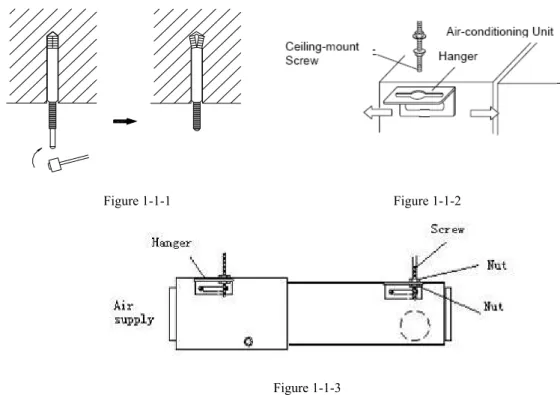
3˅ Insert a M10 expansion bolt into the hole. Drive a nail into the bolt. Refer to the profile dimensions drawing of the indoor unit for the distance between the holes. Refer to Figure 1 for the installation of the expansion boltˈas Figure 1-1-1 shows.
Figure 1-1-1 Figure 1-1-2
Figure 1-1-3
4
˅
Install the hanger onto the indoor unit as Figure 1-1-2 and Figure 1-1-3 shows.
5
˅
Install the indoor unit at the ceiling as Figure 1-1-5shows.
Air Supply
Air Intake
Nut
Hanger
Screw
mm
I
Enlargement
,
Figure 1-1-5
6
˅
Precautions for unfavorable installation:
The preparation of all pipes (connecting pipes and drainage pipes) and cables (connecting lines of wire controller, indoor unit and outdoor unit) must be ready before the installation, so as to achieve smooth installation.
Drill an opening on the ceiling. Maybe it is required to support the ceiling to ensure the evenness of it and avoid the vibration of it. Consult with the user or a construction company for details.
In case the strength of ceiling is not enough, use angle iron sections to set up a beam support. Place the unit at the beam and fix it.
After installation of indoor unit, level detection for the complete unit must be done to ensure
levelness, as shown in Fig. 1-1-6.
Air Supply Air Intake
i
Condensate Drainpipe
Level Instrument
Condensate Drainpipe Enlarged View
As the inside of the unit is in the negative pressure status, it is required to set up a backwater elbow. The requirements is: A=BıP/10+20(mm)
P is the absolute pressure inside the unit. The unit of the pressure is Pa.
Figure 1-1-6
1.1.4 Dimension Data
Unit˖mm
Model A B C D E F G H I J
IDI-09
856 571 515 790 913 680 750 100 172 220 IDI-12
IDI-18 932 627 738 894 1012 736 738 125 207 266
IDI-24 1101 395 820 1159 1207 504 1002 160 235 265
IDI-36
1011 635 820 1115 1251 744 980 160 231 290 IDI-45
IDI-50
IDI-60 1015 679 820 1115 1251 788 980 160 261 330
List of Accessories for Installation of Indoor Unit
Designation and shape Qty Description
Operation and installation instructions 1 Heat insulating material for large
connector 1 For air pipe connector of indoor unit Heat insulating material for small
connector 1
For refrigerant pipe connector of indoor unit
Heat insulation material for drain pipe 2 For packing condensate pipe and rubber plug
Nut with washer M8 8 For fixing the hanging hook
Nut with washer M10 4 Four sets, for hoisting the unit on the ceiling
Nut and spring washer 4
Hanging hook 4 For hoisting the unit on the ceiling Wire binding tie 4or 8 4 for a two-horsepower unit, 8 for other
unit.
Wire controller 1
Remote controller 1
Battery 2
Bellow 0ˈ2 or 4
0 for a 2-powerhorse unit, 2 for a 2.5ˉ3 horsepower unitˈ4 for a 4ˉ5 horsepower unit.
Power cable 1ˉ2 2 for a 4ˉ5 horsepower unit and 1 for other unit.
Connecting cable 2ˉ3 3 for a 4ˉ5 horsepower unit and 2 for other unit.
1.1.5 Installation Clearance Data
only for GFH24 and above models
Indoor Unit Figure 1-1-8
1.1.6 Drain Piping Work
1˅ Installation of Drainage Pipeline
A drainage outlet is located at both the left and right sides of the indoor unit. After selecting one drainage outlet, the other outlet shall be blocked by rubber plug. Bundle the blocked outlet with string to avoid l1eakage, and also use thermal insulation materials to wrap the blocked outlet.
When shipped out from factory, both the Drainage outlets are blocked by rubber plugs.
When connecting the drainage pipe with the unit, do not apply excessive force to the pipeline at the side of the unit. The fixing position of the pipeline shall be near the unit.
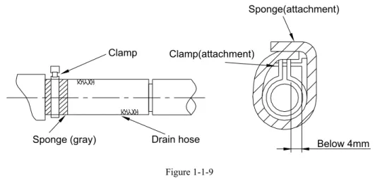
Purchase general-purpose hard PVC pipe locally to be used as the drainage pipeline. When carrying out connection, place the end of the PVC pipeline into the drainage hole. Use flexible drainage tube and tighten it with thread loop. Never use adhesive to connect the drainage hole and the flexible drainage tube. (As shown in Figure 1-1-9)
When the laid drainage pipe is used for multiple units, the common pipe shall be about 100mm lower than the drainage outlet of each set of unit. A pipe with thicker wall shall be used for such purpose.
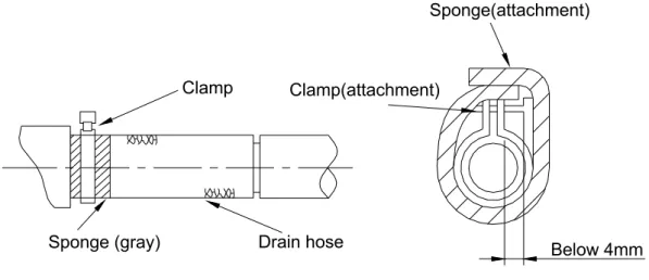
Sponge (gray) Drain hose
Clamp Clamp(attachment)
Sponge(attachment)
Below 4mm
Figure 1-1-9 2˅ Testing of Drainage System
After the electrical installation is completed, carry out the testing of the drainage system.
During the test, check if the water correctly flows through the pipelines. Carefully observe the joints to ensure that there is no leakage. If the unit is to be installed in a new house, carry out testing before decorating the ceiling.
3˅ Matters of Attention
The joint of Drainage Pipeline must not have leakage.
The Drainage Pipeline shall be installed with an inclining angel of 5̚10°, so as to facilitate the drainage of condensate. The joints of the Drainage Pipeline must be covered by thermal insulation materials to avoid generation of exterior condensate. (As shown in Figure 1-1-10)
㇑ⴆ
ߧࠍ≤㇑؍ቲ
Figure 1-1-10
1.1.7 Installation of air pipes and openings
Caution:
The air supply pipe, the air intake pipe and the fresh air pipe must be covered with a layer of thermal insulation, so as to avoid thermal leakage and condensation. Firstly apply liquid nail on the pipes, then attach the thermal insulation cotton with a layer of tinfoil. Use the liquid nail cover to fix it. Lastly use tinfoil
Insulating layer of condensate pipe
iron supports. The joints of the pipes must be sealed by glue so as to avoid leakage.
The design and installation of air pipes must be in conformity with the relevant state engineering criteria.
The edge of the air intake pipe must be at least 150mm away from the wall. The air intake must be covered with filter.
Silencing and shock absorption shall be considered in the design and installation of the air pipes. Additionally, the noise source must be far away from where people stay. The air intake shall not be located above the place where users stay (offices and rest places, etc.).
1˅ Installation of air supply duct
Installation of rectangular air duct, as shown in Figure 1-1-11
䘱
仾
എ
仾
എ
仾
Figure 1-1-11
No. Designation
No.
Designation
1
Hanger rod
5
Filter screen
2
Return duct
6
Main air supply duct
3 Canvas
duct
7
Air
outlet
4
Return air inlet
Installation of circular duct, as shown in Figure 1-1-12
Return air
Return air
Figure 1-1-12
No. Designation No. Designation
1 Hanger
rod 6 Transition
duct
2
Air return duct
7
Air supply duct
3 Canvas
duct 8
Air
diffuser
4
Return air shutter
9
Connector of air diffuser
5 Air
outlet
Note:
The above two diagrams show how back return air inlets are installed. Lower return air inlets shall
be used according to actual installation demands. The installation method is similar to the back
return air inlets. Among all air outlets, at least one keeps open. If circular duct is in use, air shall
be supplied to rooms through circular flexible insulating duct. Air supply duct and return duct
shall be heat insulated.
2
˅
Installation of fresh air duct (only limited to excessive pressure units with refrigerating output
over 6000W)
The fresh air battle, as shown in Figure 1-1-13(a), must be removed for mounting the fresh
air duct. If the fresh air duct is not in use, gaps around the battle shall be sealed by sponge.
Circular flanges are mounted for convenient connection of the fresh air duct, as shown in
Figure 1-1-14(b)
Ducts and circular flanges must be sealed and insulated sufficiently.
(a) (b)
Figure 1-1-133˅ Installation of air return duct
Square flanges at ex-factory shall be defaulted to installation at the back and the air return cover plate shall be mounted at the lower, as shown in figure 1-1-14.
Figure 1-1-14
If lower air return is demanded, the square flange and the air return cover plate should be exchanged in their respective position.
The air return duct shall be connected to the air return inlet on the indoor unit with rivets, and the other end of the air return duct is connected to an air return window. To freely adjust the height, a section of canvas duct can be fabricated and reinforced by ˔ʿ iron wires in the folding shape. A proper installation method shall be selected by taking into overall consideration of building and maintenance conditions.
No. Designation No. Designation
ˍ
Air return window
ː
Indoor
unit
ˎ
canvas
duct
ˑ
Air supply duct
ˏ
Air return duct
6
Check grating
Figure 1-1-15
4
˅
Installation of circular air supply outlet
Figure 1-1-16 1.2 Installation of Ceiling Type
1.2.1 Before Installation
When the unit arrives, please check if any damage due to transport is existent. If any hurt is found on the surface or inside, please declare to the transport company or the manufacturer in writing.
When the unit arrives, please check if any damage due to transport is existent. If any hurt is found on the surface or inside, please declare to the transport company or the manufacturer in writing.
Correct handling route and method shall be decided to prevent damage to the unit. For protecting the unit and ensuring its safety, carrying the unit with its package is recommended. If such carrying method is difficult under particular conditions, the canton shall not be removed to avoid looseness or falling during handling.
otherwise leakage of inflammable and explosive substances may lead to explosion or a fire.
1.2.2 Installation Site
Such a place where cool air can be distributed throughout the room.
Such a place where condensation water is easily drained out.
Such a place that can handle the weight of indoor unit.
Such a place which has easy access for maintenance.
Such a place where is permitting easy connection with the outdoor unit.
Such a place where is 1m or more away from other electric appliances such as television, audio device, etc.
Avoid a location where there is heat source, high humidity or inflammable gas.
Do not use the unit in the immediate surroundings of a laundry, a bath, a shower or a swimming pool.
Be sure that the installation conforms to the installation dimension diagram.
The space around the unit is adequate for ventilation
1.2.3 Caution for Installation
Adjust the distance from the unit to the ceiling slab beforehand (Refer to Figure 1-2-1).
Fix the hanger bracket to the suspension bolt (Refer to Figure 1-2-2).
Make sure that extended suspension bolt from the ceiling stays inside the arrowed position. Readjust the hanger bracket when it is outside the arrowed position. (Refer to Figure 1-2-3)
Suspension bolt stays inside the cap of indoor unit .Never remove the cap. Lift the unit and slide forward unit the dent. (Refer to Figure 1-2-4)
Screw tightly both hanger bracket setting bolts (M8) (Refer to Figure 1-2-2)
Screw tightly both hanger bracket fixing bolts (M6) to prevent the movement of the indoor unit. (Refer to Figure 1-2-2)
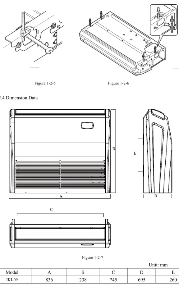
Adjust the height by turning the nut with a spanner. Insert the spanner from the hanger bracket opening. (Refer to Figure 1-2-5)
Figure 1-2-3Hanger bracket Figure 1-2-4
In case of hanging:
It is possible to install using inward facing hanger bracket by not removing the brackets from the
indoor unit. (Refer to Figure 1-2-6) Be sure to use only the specified accessories and parts for
installation work.
Figure 1-2-5 Figure 1-2-6
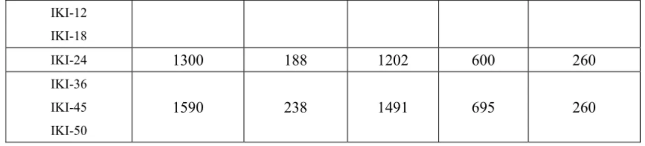
1.2.4 Dimension Data
Figure 1-2-7
IKI-12 IKI-18
IKI-24
1300 188
1202
600 260
IKI-36 IKI-45 IKI-50
1590 238
1491
695 260
1.2.5 Installation Clearance Data
Figure 1-2-8
1.2.6 Drain Piping Work
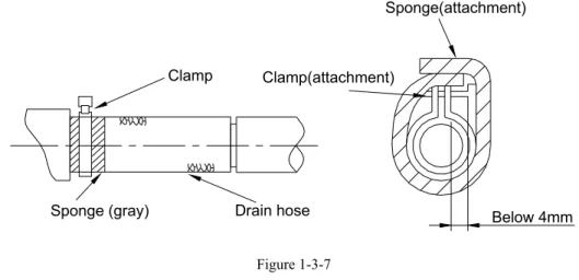
1
˅
Installation of Drainage Pipeline
A Drainage outlet is located at both the left and right sides of the indoor unit. After selecting one Drainage outlet, the other outlet shall be blocked by rubber plug. Bundle the blocked outlet with string to avoid leakage, and also use thermal insulation materials to wrap the blocked outlet.
When shipped out from factory, both the Drainage outlets are blocked by rubber plugs.
When connecting the drainage pipe with the unit, do not apply excessive force to the pipeline at the side of the unit. The fixing position of the pipeline shall be near the unit.
Purchase general-purpose hard PVC pipe locally to be used as the drainage pipeline. When carrying out connection, place the end of the PVC pipeline into the drainage hole. Use flexible drainage tube and tighten it with thread loop. Never use adhesive to connect the drainage hole and the flexible drainage tube. (As
When the laid drainage pipe is used for multiple units, the common pipe shall be about 100mm lower than the drainage outlet of each set of unit. A pipe with thicker wall shall be used for such purpose.
Sponge (gray)
Drain hose
Clamp
Clamp(attachment)
Sponge(attachment)
Below 4mm
Figure 1-2-9
2
˅
Testing of Drainage System
After the electrical installation is completed, carry out the testing of the drainage system.
During the test, check if the water correctly flows through the pipelines. Carefully observe the joints to ensure that there is no leakage. If the unit is to be installed in a new house, carry out testing before decorating the ceiling.
3
˅
Matters of Attention
The drain pipe outlet direction can be chosen from either the right rear or right.
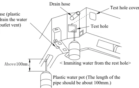
The diameter of the drain pipe should be equal to or greater than the diameter of the connecting pipe. (Vinyl tube; pipe size: 20mm; outer dimension: 26mm)
Keep the drain pipe short and incline downwards at a gradient of at least 1/100 to prevent air pockets. (Refer to Figure 1-2-10)
Figure 1-2-10
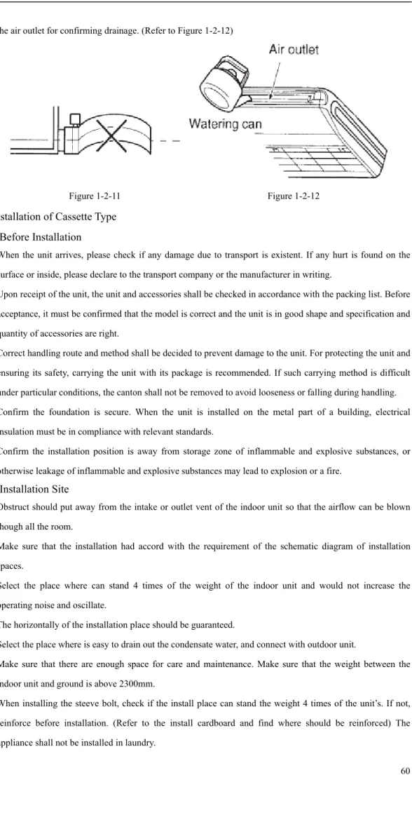
the air outlet for confirming drainage. (Refer to Figure 1-2-12)
Figure 1-2-11
Figure 1-2-12
1.3 Installation of Cassette Type
1.3.1 Before Installation
When the unit arrives, please check if any damage due to transport is existent. If any hurt is found on the surface or inside, please declare to the transport company or the manufacturer in writing.
Upon receipt of the unit, the unit and accessories shall be checked in accordance with the packing list. Before acceptance, it must be confirmed that the model is correct and the unit is in good shape and specification and quantity of accessories are right.
Correct handling route and method shall be decided to prevent damage to the unit. For protecting the unit and ensuring its safety, carrying the unit with its package is recommended. If such carrying method is difficult under particular conditions, the canton shall not be removed to avoid looseness or falling during handling.
Confirm the foundation is secure. When the unit is installed on the metal part of a building, electrical insulation must be in compliance with relevant standards.
Confirm the installation position is away from storage zone of inflammable and explosive substances, or otherwise leakage of inflammable and explosive substances may lead to explosion or a fire.
1.3.2 Installation Site
Obstruct should put away from the intake or outlet vent of the indoor unit so that the airflow can be blown though all the room.
Make sure that the installation had accord with the requirement of the schematic diagram of installation spaces.
Select the place where can stand 4 times of the weight of the indoor unit and would not increase the operating noise and oscillate.
The horizontally of the installation place should be guaranteed.
Select the place where is easy to drain out the condensate water, and connect with outdoor unit.
Make sure that there are enough space for care and maintenance. Make sure that the weight between the indoor unit and ground is above 2300mm.
When installing the steeve bolt, check if the install place can stand the weight 4 times of the unit’s. If not, reinforce before installation. (Refer to the install cardboard and find where should be reinforced) The