Volume 47 (2012)
Proceedings of the
11th International Workshop on Graph Transformation and
Visual Modeling Techniques
(GTVMT 2012)
Inter-Modelling with Graphical Constraints:
Foundations and Applications
Juan de Lara, Esther Guerra
16 pages
Guest Editors: Andrew Fish, Leen Lambers
Managing Editors: Tiziana Margaria, Julia Padberg, Gabriele Taentzer
Inter-Modelling with Graphical Constraints:
Foundations and Applications
Juan de Lara1, Esther Guerra1
1(Juan.deLara, Esther.Guerra)@uam.es
Department of Computer Science Universidad Aut´onoma de Madrid, Spain
Abstract: Model-Driven Engineering (MDE) promotes an active use of models in the different phases of the development, so that the construction of systems usually involves a number of models expressed in different languages and levels of abstrac-tion; therefore, there is the constant need to compare, generate and update models and their relations.
We callinter-modelling to the activity of building models that describe how
mod-elling languages should be related. This includes many MDE activities like the spec-ification of model-to-model transformations, the definition of model matching and traceability constraints, and the development of inter-model consistency mantainers. While most approaches build different operational programs to handle each activity
separately, we propose using a high-level specification language called PAMOMO
to specify inter-models in a declarative, graphical, bidirectional way. This specifica-tion can be compiled into operaspecifica-tional mechanisms to solve different inter-modelling activities like transformation, model comparison and traceability support. Other
us-age scenarios for PAMOMOare the specification of transformation contracts and the
automated testing of transformations.
Keywords: Model Transformation, Inter-Modelling, Graph Constraints, Bidirec-tionality
1
Introduction
Models are the core assets of the development in Model-Driven Engineering (MDE). The ratio-nale is that they allow a high-level, more intentional description of systems, with less accidental details because they frequently use concepts of the problem domain and not of the solution space. Hence, models are used to specify, test, maintain and generate code for the final applications. In this context, model manipulations become a key activity which may involve one model (e.g. for model animation, simulation and refactoring) or several models (e.g. when transforming a model to a different modelling language, or when comparing, merging or establishing traceability links between models). In the latter case, the usual approach is building a different program for each particular manipulation, regardless they involve the same modelling languages. This sometimes leads to an unnecessary proliferation of heterogeneous programs which become difficult to main-tain synchronized when the involved languages change.
how the models of different modelling languages should be related. Most manipulations that
involve several models can be specified usinginter-models. In this paper, we give an overview of
our inter-modelling language PAMOMO (for Pattern-based Model-to-Model specification
lan-guage) [GLKP10b]. This is a bi-directional, declarative specificationlanguage (in contrast to
an implementation language) where the same specification can be used to solve several model manipulation scenarios. For this purpose, we provide several notions of conformance or sat-isfaction, and several compilations into operational mechanisms. This paper will present the
foundations of PAMOMO[GLKP10b,GLO11,LG08] as well as some applications [GLKP10a,
GLW+12,GL12].
The rest of the paper is organized as follows. Section2introduces some inter-modelling
ac-tivities. Then, Section3overviews the foundations of PAMOMO, including its syntax, different
notions of conformance, and compilations into operational mechanisms for different scenarios.
Section4 illustrates its use with two examples. The first one applies an inter-modelling
spec-ification to the discovery of design patterns in meta-models. The second one uses PAMOMO
as a means to specify contracts for model transformations, and their application for automated
testing. Section5compares with related work and Section6concludes the paper.
2
Inter-Modelling Activities
This section introduces some inter-modelling activities of interest, namely, model-to-model trans-formation, model matching and traceability between models.
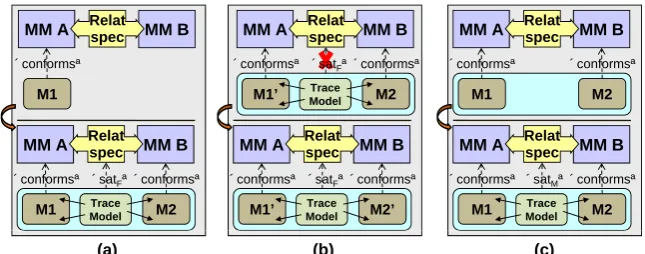
In model-to-model transformation, a source model conforming to a source meta-model is transformed into a target model conforming to a target meta-model. In the simplest case, the
target model is created from scratch. This scenario, calledbatch transformation, is depicted
schematically in Figure1(a). In this case, the transformation creates a target model together with
a trace model containing mappings between source and target model elements. If we need to transform also backwards (from target to source), and we are using an operational transforma-tion language, then we need to implement a different transformatransforma-tion for each directransforma-tion. Instead, we propose using bi-directional, declarative inter-modelling specifications from which deriving operational transformations for both directions. Thus, a model transformation definition can be seen as an inter-modelling specification that states the conditions under which a target model is considered a correct transformation of a source model, and vice versa. For each direction we
use a different notion of conformance. The figure usesSATF to convey that we use the
spec-ification to checkforward conformance: whether the target model can be considered a correct
transformation of the source. Backward conformance, denoted as SATB, is defined
symmetri-cally. We say that two models aresynchronizedif they conform both forwards and backwards to
the specification.
A more complex scenario is the so-called incremental transformation. In this scenario, a
source model is initially transformed into a target model (e.g. using a batch transformation), then the source model is updated, and the incremental transformation must propagate the performed changes to the target model. This is usually done for efficiency reasons, to avoid having to regenerate the target model from scratch, or to prevent the overriding of any manual change made
MM A
M1 «conforms»
Trace Model
«conforms» «satF»
MM B
Relat spec
MM A
M1 «conforms»
MM B
Relat spec
M2 TraceModel
«conforms» «satF»
MM A
M1’ «conforms»
MM B
Relat spec
M2’ ModelTrace
«conforms»
MM A
M1 «conforms»
MM B
Relat spec
M2
Trace Model
«conforms»
MM A
M1’ «conforms»
MM B
Relat spec
M2
«conforms»
MM A
M1 «conforms»
MM B
Relat spec
M2
«satM»
«satF»
(a) (b) (c)
Figure 1: Some inter-modelling activities: (a) forward batch transformation, (b) forward incre-mental transformation, (c) model-matching.
synchronization scenario, both the source and target models may be modified after they were
consistent, and the operational mechanism may have to update them to recover their consistency. In addition to model transformations, another interesting inter-modelling activity is to
estab-lishtraceabilitybetween models [PDK+11,WP10]. In this case, given two unrelated models,
the operational mechanism must produce a trace model relating source and target elements so that both models (or parts of them) become synchronized. This can be used to trace the origin or provide semantics to the different model elements, or as a previous step to the synchronization scenario. In the latter case we first produce the traces between two given unrelated models, and then apply the synchronization operational mechanism.
Model matchingis the last inter-modelling activity we tackle. It is useful when we want to
compare models, or as a previous step to model merging [Kol09]. The scenario is depicted in
Figure 1(c). In this case, a trace model is created identifying all elements in the source and
target models considered equivalent according to the inter-modelling specification. After the operational mechanism has created the trace model, the related models should conform to the specification. This can be checked by using a special notion of conformance, different from the
previous ones, depicted in the figure asSATM.
Altogether, an inter-modelling specification is used in two ways. First, it is used to generate operational mechanisms for solving a particular scenario (e.g. creating a target model given
a source one, as shown in Figure 1(a)). Secondly, it is used tocheck the conformance of a
set of related models for a particular scenario. The next section provides an overview of our specification language for inter-modelling, the way it is used to check conformance of models with respect to specifications, and the methods to synthesize operational mechanisms for the different scenarios.
3
PAMO
MO: A Specification Language for Inter-Modelling
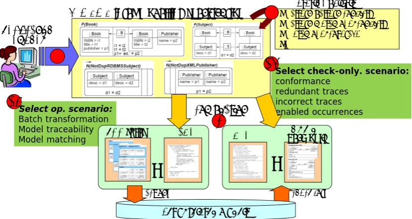
PAMOMO is a pattern-based, formal, declarative, bi-directional language. In our approach,
shown in Figure2, designers can use this language to build inter-modelling specifications stating
PAMOMOinter‐modelling specification
Specification Designer
1
• Pattern‐pattern conflicts • Pattern‐metamodel conflicts • Metamodel coverage •…
Static Analysis
2
2
Select op. scenario:
Batch transformation Model traceability Model matching
3a
Select check-only. scenario:
conformance redundant traces incorrect traces enabled occurrences
3b
check for…
OCL CheckQVT‐‐onlyR
…
compilation
EOL
…
TGG rules
4
4
act on…
Set of related models
Figure 2: Architecture of our approach.
two models. Such a specification can be analysed (label “2” in the figure), for example to detect conflicts or contradictions between patterns, to find redundant patterns, or to identify discon-formities between the patterns and the meta-models of the languages being related. It is also possible to measure the degree of coverage of a (source or target) language by a specification, and analyse whether certain classes only participate in negative (i.e. non-generative) patterns. This provides an indication of the completeness of a specification.
Specifications can be used both in operational and check-only modes for each particular inter-modelling scenario (up to now, batch transformation, model traceability and model matching).
For the operational mode, we generate operational Triple Graph Grammar rules [Sch94] or
pro-grams written in the Epsilon Object Language (EOL) [KPP06] that implement the expected
be-haviour for the chosen scenario. EOL is a variant of OCL [OCL] with side effects that enable for
example creating new objects or setting attribute values. For the check-only mode, we generate OCL code that can be used to assert conformance of models with respect to the specification for the chosen scenario, as well as to identify incorrect, redundant or missing traces between models.
Additionally, for the batch transformation scenario, we can generate QVT-Relations code [QVT]
that can be executed in check-only mode with a QVT engine like ModelMorf [Mod] to check for
disconformities of models with respect to the specification. As we will see in Section4.2, this is
especially useful in model transformation testing [GLW+12].
3.1 Models and their relations, algebraically
The building blocks of PAMOMOpatterns are the so-calledconstraint triple graphs, an algebraic
construction that we have defined to relate two models. In this section we present this construct.
We keep the discussion on an informal level, and refer to [GLO11] for technical details.
c0: class name=“person” persistent=true t0: table name=“person” :C2T c1: class
S C T
c1: class name=“person” persistent=true t1: table name=“person” :C2T a: attribute name=“age” type=“integer” public=true fe a tu re
(a) A triple graph
c0: class name=X persistent=P t0: table name=Y :C2T X=Y P=true X=Y P=true
(b) A CT-graph
c0: class name=N1 persistent=P1 t0: table name=NT1 :C2T c1: class name=N2 persistent=P2 t1: table name=NT2 :C2T fe a tu re a: attribute name=A type=T public=P3 fe a tu re
N1=“person”
N2=“person”
P1=true P2=true
P3=true A=“age”
T=“integer”
NT1=“person”
NT2=“person”
(c) A CT-graph representation of the triple graph in (a)
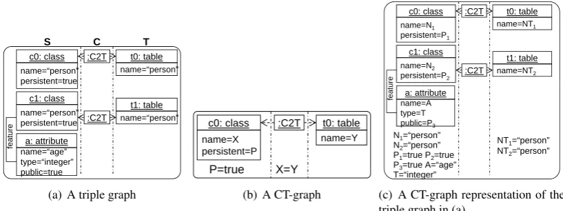
Figure 3: A unified view of triple graphs and constraints.
values are represented as data nodes, and attributes are edges connecting graph nodes with data nodes. For inter-modelling, we need to relate models through a trace model. For this purpose,
we use triple graphs [Sch94], which are structures made of a source and a target graph (S and
T) related through a correspondence graph (C). The correspondence graph represents the trace
model and contains the mappings (or traces) between the other two graphs. These mappings are
given by two graph morphismscs:C→Sandct:C→T. A graph morphism is a collection of
set functions relating the sets of nodes, edges and attributes in two graphs, and preserving the
graph structure. As an example, Figure3(a) shows a triple graph relating a class diagram (in
abstract syntax) and a relational data-base schema. The source graph contains one edge (labelled
feature) and threegraphnodes:c0,c1anda. The first two graph nodes have two attributes each
(nameandpersistent), while the last graph node has three attributes. We represent graphs using
the usual UML object diagram notation, showing attributes inside a box compartment close to the owning graph node, and indicating the typing after the node name, separated by a colon.
An inter-modelling language needs to express constraints on related models. For this purpose,
we defineconstraint triple graphs (CT-graphs in short) as triple graphs where the data nodes
(i.e. the attribute values) are replaced by a finite set of variables and a formulaα constraining
their value. Additionally, CT-graphs are defined over a signatureΣ= (S,op)that contains the
sorts and operations used by the formulaα. As an example, Figure3(b)shows a CT-graph. We
usually omit the conjunctions in the formulaαand split it in three parts:αS, containing the terms
dealing with variables of the source model only,αT containing the terms dealing with variables
of the target model only, andαCwith the terms that relate variables in both models. We display
αSinside the source compartment (seeP=truein the figure),αCin the middle (seeX=Yin the
figure), andαT in the target compartment (truein this case as no formula is shown).
Triple graphs can be represented as CT-graphs by creating a variable for each attribute value, and including a conjunctive term with the equality of each variable and its value in the formula,
as Figure3(c)shows. In this way, we only need to handle one kind of structure. Thus, finding
an occurrence of a CT-graph in a triple graph amounts to defining a morphism between two
CT-graphs, called CT-morphism. A CT-morphism f:M1→M2between two CT-graphsM1and
c0: class
name=X persistent=P
P=true
c0: class
name=X persistent=P
X=“Person” P=true P1=true A=name T=“String”
c0: class
name=X persistent=P
t0: table name=Y :C2T
X=Y P=true
M1
M2 C
a: attribute name=A type=T public=P1
feat
ure
c0: class
name=X persistent=P
X=“Person” P=true P1=true A=“name” T=“String”
G
a: attribute name=A type=T public=P1
feat
ure
t0: table name=Y :C2T
X=Y
a
b c
d P.O.
Figure 4: Glueing of CT-graphs: Pushouts.
the formulaα1 in M1 should be weaker or equal than the formula α2 inM2. More in detail,
CT-morphisms must fulfil three implications: α2S⇒α1S,α2T ⇒α1T, andα2⇒α1. For instance,
there are two CT-morphisms from the CT-graph in Figure3(b)to the one in Figure3(c). The first
one identifies equally named elements, and the second one identifiesc0 withc1 andt0 witht1.
A useful operation in our context is the merging or glueing of two CT-graphs M1 and M2
through some common elements given by a CT-graphCand two CT-morphismsa:C→M1and
b:C→M2. This is called apushoutin category theory [EEPT06]. This operation yields a new
CT-graphGand two CT-morphisms fromM1andM2toG. The resulting CT-graphGcontains
a copy of the elements present in the other two graphs, without duplication, and its formula is
the conjunction of the formulas inM1 andM2. Figure4 shows an example of pushout, where
CT-graphsM1andM2 are glued through their common elementc0. The resulting CT-graphG
contains the different elements ofM1andM2glued via the common part, so that elementc0 only
appears once, and its formula is the conjunction of the formulas inM1andM2.
3.2 The PAMOMOspecification language
In this section we briefly introduce PAMOMO, our pattern-based language for inter-modelling.
For technical details, the reader can consult [GLO11].
A PAMOMOspecification is made of a set of patterns. Patterns are built on the notion of
CT-graph presented in the previous subsection. A pattern describes in a declarative way a relation between two models. If the relation is allowed, then we say that the pattern is positive (P-pattern), whereas if the relation is forbidden, then we say that the pattern is negative (N-pattern).
P-patterns are made of a main CT-graphQdefining the allowed relation, an optionalenabling
condition Cwith a CT-morphismq:C→Q, and a setNPre={ci:Q→Ci}i∈Pre ofdisabling
conditions, which may be empty. The enabling and disabling conditions can be used to reduce
the scope of a pattern to the locations where the enabling condition is met, and the disabling conditions are not. N-patterns have the same structure as P-patterns, but the interpretation is that
p: Package
name=X persistent=P
s: Schema
name=Y
:P2S
Y=X P=true
PackageSchema
(a) A positive pattern
p: Package name=X persistent=P1
s: Schema name=Y :P2S
NoPersistentClasses
c: Class name=C
t: Table name=T :C2T
Y=X C=T P1=true∧P2=false name=C persistent=P2
name=T
(b) A negative pattern
c: Class name=X persistent=P
t: Table name=Y m:C2T
Y=X P=true c: Class
p: Class
parent ClassTable
N(Parent)
name=X persistent=P
P=true
m:C2T t: Table name=Y
Y=X
(c) A pattern with a disabling condition
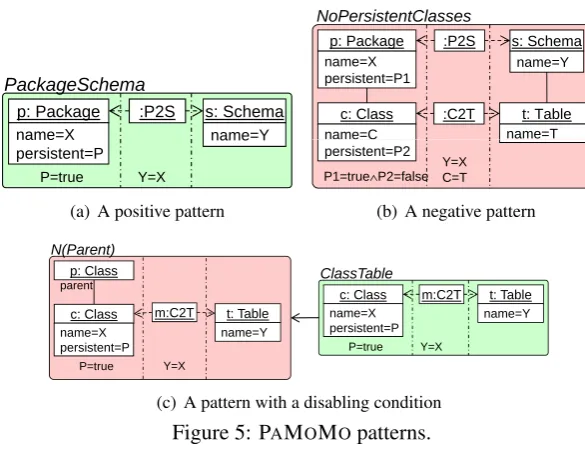
Figure 5: PAMOMOpatterns.
As an example, Figure 5gathers some patterns that belong to the specification of the
“clas-sical” class-to-relational transformation (see the appendix of [QVT]). Figure 5(a) shows a
P-pattern specifying how Packages and Schemas should be related. In particular, it specifies
that if there is a trace mapping between a package and a schema, then they have the same name and the package is persistent. We will see that the precise meaning of the pattern depends on the inter-modelling scenario to be solved. Visually, we depict P-patterns with green background,
and N-patterns with red background. Figure5(b)shows an N-pattern stating that non-persistent
classes should not be related to tables. In this way, PAMOMOspecifications can indicate not only
how elements should be related, but also forbidden situations, i.e., it supports a non-constructive
specification style. Finally, the P-pattern in Figure 5(c) has a disabling condition with label
N(Parent). The main CT-graph, with labelClassTable, demands a trace relating persis-tent classes and tables with same name. The disabling condition forbids the existence of a parent for the class. Altogether, the trace between the class and the table is only required to occur when the class does not have a parent.
An inter-modelling specification is made of a set of declarative patterns. As we will explain in the following sub-section, patterns are given different semantics depending on the usage scenario (forward/backward transformation, matching, traceability, etc.). The idea is to interpret patterns
as special graph constraints [EEPT06] that should hold (for P-pattern) or not (for N-patterns) in
the CT-graph where we evaluate the specification.
3.3 Satisfaction checking
Patterns are interpreted differently depending on the inter-modelling scenario [GLO11]. For
instance, if our purpose is performing forward batch transformation, then the P-pattern in
Fig-ure5(a)is interpreted as“for each persistent package, there must be a schema with same name”.
c: Class name=X persistent=P t: Table name=Y :C2T Y=X P=true c: Class p: Class parent ClassTable name=X persistent=P P=true c: Class name=X persistent=P P=true t: table c: class :C2T
Forward pre-condition Negative Forward pre-condition
c1: class name=N2 persistent=P2 t: table name=NT :C2T
N1=“person” N2=“employee”
P1=true P2=true NT=“person” c: class
name=N1 persistent=P1
:C2T
parent
(a) Forward satisfaction (SATF)
c: Class name=X persistent=P t: Table name=Y :C2T Y=X P=true c: Class p: Class parent ClassTable name=X persistent=P P=true c: Class name=X persistent=P P=true t: table name=NT1 c: class name=N1 persistent=P1 :C2T t: Table name=Y Y=X t: Table name=Y Y=X :C2T Match pre-condition Negative Match pre-condition
c1: class name=N2
persistent=P2
:C2T N1=“person” N2=“person” P1=true P2=true
NT1=“person” persistent=P1
NT2=“person” t1: table name=NT2
:C2T
(b) Match satisfaction (SATM)
Figure 6: Different notions of satisfaction.
must be a persistent package with same name”. The model matching and model traceability
scenarios consider the source and target of patterns at the same time. For instance, in model
matching, the same pattern is interpreted as “for each package and schema with same name,
there should be a trace relating them”. Note that, in all cases, there is a part of the pattern that
is sought with a “for-all” iteration, and for each occurrence, the existence of the whole pattern is demanded. However, depending on the specific inter-modelling scenario, the domain of the sought part (source, target or both) and how this part is constructed differs.
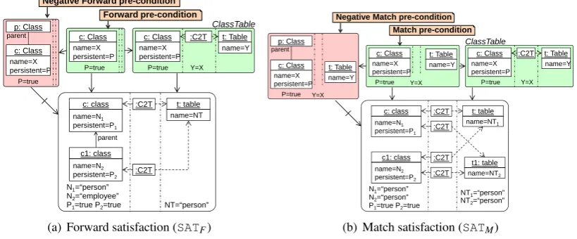
In forward satisfaction (i.e. in the forward transformation scenario), the sought part is called
forward pre-condition. This is built by glueing the enabling condition of the pattern (if there is
any), together with the source part of the main CT-graph. Moreover, we built so-called negative forward pre-conditions by restricting each disabling condition of the pattern to the source part
(see [GLO09] for the technical details). This construction is illustrated in Figure6(a). As pattern
ClassTable does not have an enabling condition, the forward pre-condition is equal to the source CT-graph. The negative forward pre-condition is made of the source of the pattern’s disabling condition.
A CT-graph M forward-satisfies a positive patternP, written M|=SATF P, if for each
occur-rence ofP’s forward condition such that there is no occurrence of P’s forward negative
pre-conditions, there is some occurrence ofP’s main CT-graph. These conditions are expressed using
CT-morphisms, as Figure6(a)shows. In the figure, there is only one morphism from the forward
pre-condition that does not commute with a morphism from the forward negative pre-condition.
This morphism is the one identifying cin the forward pre-condition and the model. For this
morphism, there is a commuting morphism from the pattern’s main constraint. Thus, the model forward-satisfies the pattern.
The forward satisfaction of a negative pattern is similar. In this case, for each occurrence of its forward pre-condition, there should not be an occurrence of its main CT-graph. The definition of backward satisfaction for patterns is symmetric to the forward case.
A CT-graph M forward-satisfies a specificationS, writtenM|=SATF S, if it forward-satisfies
all the patterns inS. A patternPspans a languageSEMF(P) ={M|M|=SATF P}, which is the
composi-tional, as the semantics of a specificationSis the intersection of the languages of all its patterns,
SEMF(S) =
T
P∈SSEMF(P).
In model matching, we use a different notion of satisfaction in which, first, the so-calledmatch
pre-conditionis sought. The match pre-condition of a pattern is made of the source and target
parts of its main CT-graph, glued together with the pattern’s enabling condition (if there is any).
Moreover, we built so-callednegative match pre-conditionsby restricting each disabling
condi-tion of the pattern to its source and target parts. This construccondi-tion is illustrated in Figure6(b).
The satisfaction checking procedure is similar as before, as for each occurrence of the match pre-condition that does not commute with any occurrence of the match negative pre-conditions,
there should be a commuting occurrence of the pattern’s main CT-graph. In Figure 6(b), the
CT-graphMmatch-satisfies the pattern, writtenM|=SATM ClassTable, as for each combination
of class and table equally named, a trace exists.
The notions of satisfaction presented so far make sure that the source, target and trace models contain all necessary elements according to a specification. However, they do not check whether unnecessary source and target elements or whether incorrect traces exist in the models. This closed-world assumption for a given specification can also be considered in order to detect in-correct traces that can be subsequently deleted by an operational mechanism, or else change the source or target models to achieve consistency.
In practice, we generate OCL code from the patterns and use it against a given CT-graph
to check whether it satisfies a specification [GLKP10a]. As an example, Listing 1shows the
generated OCL code to check forward satisfaction of patternClassTable.
1 operationforwardsat ClassTable() :Boolean{
2 returnClass.allInstances().forAll(c|c.persistent=trueand notClass.allInstances().exists(p|c.parent.includes(p) )
3 impliesTable.allInstances().exists(t|
4 C2T.allInstances().exists(m|m.source=candm.target=tandcheckatt ClassTable(c, t, m)));
5 }
6 operationcheckatt ClassTable( c:Class, t:Table, m:C2T ) :Boolean{
7 varX:=c.name;
8 varY:=t.name;
9 returnY=X;
10 }
Listing 1: OCL code to check forward satisfaction of pattern in Figure5(c).
Once we have seen different notions of satisfaction, the next subsection overviews the gener-ation of opergener-ational mechanisms to enforce the patterns.
3.4 Generation of operational mechanisms
Each inter-modelling scenario requires a different operational mechanism. For example, in for-ward transformation, the target and trace models are created from scratch starting from the source model. In model matching and model traceability, a trace model is built mapping elements in the source and target models.
We implement these operational mechanisms by generating operational TGG rules from the
patterns in the specification [GLO09], using a similar procedure to the generation of operational
TGG rules from declarative TGG rules [Sch94]. In our case, a TGG operational rule is a
non-deleting rule, made of a left-hand side (LHS) CT-graphL, a right-hand side (RHS) CT-graph
Inter-Modelling with Constraints
c: Class :C2T t: Table
LHS
c: Class :C2T t: Table
RHS=NAC1
c: Class :C2T t: Table
NAC2 :C2T :Table
c: Class :C2T t: Table
P=false a: Attribute name=X public=P c: Column name=Y X=“__”+Y :A2C c: Class :C2T t: Table
PrivateAttribute2Column P=false a: Attribute name=X public=P P=false a: Attribute name=X public=P c: Column name=Y X=“__”+Y :A2C c: Class :C2T t: Table
P=false a: Attribute name=X public=P c: Column name=Y X=“__”+Y :A2C
(a) A pattern with enabling condition
c: Class :C2T t: Table
LHS
c: Class :C2T t: Table
RHS=NAC1
c: Class :C2T t: Table
NAC2 :C2T :Table
P=false name=X
public=P name=Y
X=“__”+Y
:A2C c: Class :C2T t: Table
P=false a: Attribute name=X public=P P=false a: Attribute name=X public=P c: Column name=Y X=“__”+Y :A2C c: Class :C2T t: Table
P=false a: Attribute name=X public=P c: Column name=Y X=“__”+Y :A2C
(b) Generated forward rule
LHS
c: Class :C2T t: Table
P=false RHS=NAC1 a: Attribute name=X public=P c: Column name=Y X=“__”+Y :A2C c: Class t: Table
P=false a: Attribute name=X public=P c: Column name=Y X=“__”+Y :C2T
(c) Generated model matching rule
LHS
RHS
a: Attribute :A2C c: Column c: Class :C2T t: Table
P=false a: Attribute name=X public=P c: Column name=Y X=“__”+Y :A2C NAC
a: Attribute c: Column
(d) Generated trace deleting rule
Figure 7: Generation of operational TGG rules.
and a setNACpost={nj: R→Nj}of negative post-conditions. A rule can be applied to a
CT-graphM if a CT-morphismm:L→Mexists, and there is no commuting morphism from any
negative application condition inNACpre. If such a CT-morphism exists, the rule can be applied
by glueingMandRthrough its common elements inL(i.e. by a pushout as seen in Figure4).
As a result, Mis enlarged with the new elements in R, and the formula inRis added toM as
well. After applying the rule, the negative post-conditions inNACpost are checked, and if some
of them are found in the resulting CT-graph, then the rule application is undone1. A grammar is
made of a set of rules. Applying a grammar means an iterated application of its rules (chosen in random order) until no rule is further applicable.
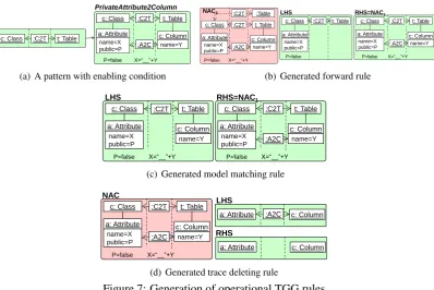
In our case, if the inter-modelling scenario is forward transformation, then we generate a rule from each P-pattern. The LHS of the rule contains the forward pre-condition of the pattern (i.e. the source of its main CT-graph together with the enabling condition). The RHS of the rule contains the main CT-graph. A number of negative application conditions are added to the rule to
ensure termination, as explained in [GLO09]. Moreover, if the specification contains N-patterns,
then these are transformed into negative post-conditions of the generated rule. As an example,
Figure7(a)shows a P-pattern with an enabling condition, and Figure7(b)contains the forward
transformation rule generated from the pattern.
Our generation procedure yields grammars that are terminating (i.e. their execution eventu-ally stops) and correct (i.e. each generated terminal CT-graph forward-satisfies the
specifica-tion) [OGLE09]. However, in order to achieve completeness (i.e. being able to generate all
pos-sible models that satisfy the specification) we need to generate additional rules with increasingly
EClass
EOperation
EReference
eSuperTypes
* * ClassBind
OpBind
RefBind Instance
ClassRole OpRole RefRole
PatternRole
name: String DesignPattern
name: String
1..*
Ecore Design pattern vocabulary
(a) Meta-model for design pattern discovery
cmpn: EClass Abstract=true
cmps: EClass Abstract=false leaf: EClass
eSuperTypes
eSuperTypes
ch: EReference containment=true
eStructuralFeatures eType
: Instance
: ClassBind
: ClassBind
: ClassBind
: DesignPattern
: ClassRole name=“Component”
: ClassRole name=“Composite”
: ClassRole name=“Leaf” Composite Design Pattern
: EReference containment=true
eType
NAC name=“Composite”
(b) Specifying theCompositedesign pattern
Figure 8: Inter-modelling for the discovery of design patterns.
bigger LHS. The generated grammar is in general not confluent because, indeed, a specification may admit several target models that are considered correct transformations of the same source
model [OGLE09].
The generation of operational TGG rules to implement other inter-modelling scenarios like
model matching and traceability is similar [GLO11]. As an example, Figure 7(c) shows the
rule generated from the pattern in Figure 7(a) for model matching. Moreover, if we consider
a closed-world assumption, then we need additional rules to delete incorrect traces between models. These rules can also be generated from the inter-modelling specifications. For instance,
the rule in Figure7(d)deletes an incorrect trace between an attribute and a column if the trace
does not conform to any P-pattern in the specification. The NAC forbids deleting the trace in
case the trace context is the one specified by thePrivateAttribute2ColumnP-pattern,
assuming this is the only P-pattern containing such trace type.
4
Examples
Next, we present two applications of our inter-modelling approach.
4.1 Discovery of design patterns
We have implemented a general inter-modelling specification tool, based on PAMOMO, over
the Eclipse Modeling Framework (EMF) [SBPM08]. In this tool, patterns can be specified
us-ing a textual syntax, and then can be compiled into OCL expressions and EOL programs that implement the notions of satisfaction and the behaviour of the operational TGG rules presented before. In this subsection we show an application of this tool to the discovery of design patterns on meta-models.
In the model matching scenario, an inter-model specifies similarity criteria between two pos-sibly heterogeneous models. We have used this semantics to find and annotate occurrences of
design patterns [GHJV94] in meta-models. In particular, the two models to compare are: (a)
the meta-model and (b) a model with the design pattern roles, for each design pattern. In this case, each inter-modelling pattern in the specification corresponds to the description of a design pattern. Thus, whenever an occurrence of an inter-modelling pattern is found, the corresponding
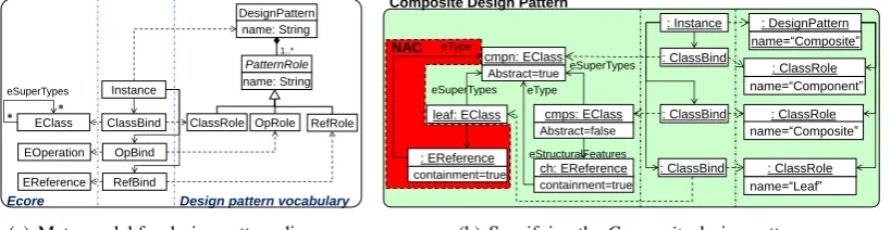
Figure8(a)shows an excerpt of the meta-models used for this example. The left part corre-sponds to a small fragment of the ecore meta-model, while the right part contains the vocabulary meta-model used to specify the roles of the elements (classes, operations, references) involved in design patterns. The trace meta-model in between permits assigning design pattern roles to the elements in the ecore meta-model. For this example, we used an extended theory where traces
may point to just one element in one of the models (e.g., node Instance) and edges in the
trace model are not mapped [GLKP10a]. Then, each design pattern is specified as a PAMOMO
inter-modelling pattern. Figure8(b) shows a simplified version of the Composite design
pat-tern [GHJV94]. There is a disabling condition, which is depicted using a compact notation
en-closed in a polygon labelled as NAC together with the main CT-graph. The disabling condition
forbids containment references from theLeafclass to theComponentclass.
To identify design patterns in a meta-model, we have to give as input the ecore meta-model of
interest, as well as an instance of the meta-model to the right of Figure8(a). The matching
mech-anism generates traces identifying the occurrences of the different design patterns specified in the inter-modelling patterns. Such traces can be maintained correct by the generated operational mechanisms, creating new traces whenever a new instance of a design pattern is created, and deleting incorrect traces whenever some meta-model change deletes a design pattern instance.
4.2 Transformation contracts for automated testing
The most widely adopted means to build transformations is by the use of transformation
im-plementation languages like ATL [JABK08], ETL [KPP08] or simply Java. These approaches
are likely the most immediate to build transformations, as they are well supported by develop-ment environdevelop-ments. However, their abstraction level is close to programming languages, so that transformations often become difficult to program, test, maintain and understand.
To simplify the previous tasks, in previous works we have proposed using inter-models as a
way to specifyrequirementsfor model transformations. In particular, we use PAMOMO
spec-ifications as contracts for model transformation implementations, so that they can be used to
automate their testing [GLW+12]. A PAMOMO specification can be used to specify: (a)
pre-conditions, (b) post-conditions and (c) invariants that a transformation implementation needs to fulfil. Pre-conditions specify conditions that any input models to the transformation must satisfy.
They are specified as PAMOMOpatterns where the correspondence and target parts of the main
CT-graph is empty. Post-conditions specify conditions that every output model resulting from
the transformation must satisfy. They are specified as PAMOMOpatterns where the source and
the correspondence parts of the main CT-graph is empty. Invariants specify properties that pairs of source/target models should satisfy (i.e. patterns where the source and target are not empty).
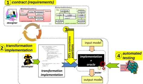
Figure9 shows a scheme of our approach. First, the transformation designer can gather
re-quirements for the transformation in the form of PAMOMOpatterns. These patterns specifywhat
the transformation is to do. Then, animplementationcould be constructed using any
transfor-mation language (e.g. ATL, ETL or simply Java)2. This implementation can be tested against its
requirements. For this purpose, we have currently two approaches. In the first one, we generate
2Although we can produce operational mechanisms (operational TGGs) for model transformation from our
designer … contract (requirements)
1
c: Class
P(InheritedAttributes)
p: Class
a: Attribute name=A c.general->includes(p)
t:Table
co:Column name=A Class pa: Package Relational s: Schema isPersistent = true name=C name=C p:Class
N(NoRedefinedAttrs) a:Attribute
name=X c:Classar:Attribute name=X c.general->includes(p) Class Relational pa:Package
3
developer
tester
transformation implementation
2
automated testing
4
transformation implementation
implementation + oracle input model
output model 3
O
C
L
c
o
r
r
e
c
t
n
e
s
s
a
s
s
e
r
t
io
n
s
Figure 9: Automated testing with PAMOMO
OCL expressions from the specification, which are evaluated before and after the
transforma-tion executransforma-tion [GLKP10b]. In particular, the pre-conditions are checked before the execution,
whereas the post-conditions and invariants are checked after the execution. If the input/output
models satisfy all generated OCL expressions (i.e. the expressions return true) then it means
that the models satisfy the specification. In this way, the generated OCL code acts as a partial oracle function for transformation testing. In our second approach, we generate QVT-Relations
code from the requirements (instead of OCL) [GLW+12]. The advantage is that executing the
QVT-Relations code in check-only mode using an engine like ModelMorf provides more infor-mation about the reasons for failure than an OCL expression. In particular, the engine reports the location in the models where the specification is not fulfilled. Please note that, normally,
PAMOMO contracts are under specifications of the behavior that transformations
implementa-tion should satisfy. Moreover, the meta-models used by the implementaimplementa-tions can be refinements of those used in the specification.
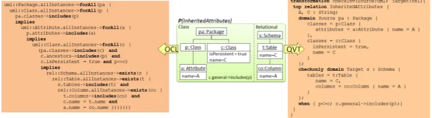
As an example, Figure10shows a pattern capturing a transformation requirement: inherited
attributes should be transformed into columns of the table created for the child class. The figure shows to the left the OCL code generated from the pattern, which checks the satisfaction of the pattern by a pair of models. To the right, the figure shows the QVT-Relations code generated from the same pattern for the same purpose. In both cases, it can be observed that the generated
code is less compact than the original pattern [GLW+12].
5
Related Work
We define inter-modelling as the activity of modelling relations between models. Thus, we
describe such relations as models, as opposed to hard-coding specific mechanisms for each con-crete scenario. In general, models tend to be more flexible, understandable and maintainable than
lower-level programs. Inter-models can be seen as a generalization of the term
transformation-model[BBG+06], comprising additional inter-modelling scenarios other than transformations.
Our approach is closely related to Triple Graph Grammars (TGGs) [Sch94]. In TGGs, an
Figure 10: A pattern capturing a transformation requirement (middle), and its compilation into OCL (left) and QVT-Relations (right)
correctly related if they can be produced by the declarative TGG. Therefore, one must resort to parsing. In our case, an inter-model is made of constraints, and two models are correctly related
according to some scenarioif they satisfy all constraints in the specification. To our knowledge,
there is no equivalent to our negative patterns in TGGs. In practice, we check whether a set of models satisfy a specification by deriving appropriate OCL expressions. Therefore, an advan-tage of our approach is that we have different notions of satisfaction depending on the scenario. Moreover, the generated OCL can be used in existing MDE tools. For instance, we can use ex-isting OCL-based constraint solvers to generate models satisfying a specification, which may be
useful for transformation testing [Gue12].
Another inter-modelling tool is the ATLAS Model Weaver (AMW) [FBJ+05], which is used
to establish relationships (i.e. links) between models. The links are stored in a so-called weaving model, conforming to a weaving meta-model. Simple source-to-target transformations can be derived from a weaving model, but only when the source and target meta-models are very sim-ilar. The definition of complex conditions enabling the creation of traces, like those that can be
encoded with PAMOMO, requires defining additional conditions at the model level by means of
patterns of source and target instances, which is not supported in AMW.
In [DMC12], a formal framework for inter-modelling is proposed based on Kleisly categories. Instead of using patterns to specify relations between models, model queries are defined, which enrich the models with derived information. Then, trace models are direct mappings between the enlarged models. It is up to future work to identify how our patterns correspond to such queries, and how such framework can be used for the inter-modelling scenarios we have presented.
6
Conclusions and Future Work
enforce their conformance to the specifications for a certain scenario. We have presented the
inter-modelling language PAMOMO, which follows a declarative, bi-directional, relational style.
Finally, we have shown several examples illustrating its use in practice.
We are currently working on using PAMOMOto specify transformation requirements, and for
transformation testing. In particular, we are exploring the automatic generation of input models for testing, covering all relevant properties of the transformation according to the specification.
We are also working on providing tool support for using PAMOMO as a part of a family of
languages, calledtransML[GLK+12], for the engineering of model transformations.
Acknowledgements: Work sponsored by the Spanish Ministry, with project “Go Lite” (TIN2011-24139), and the R&D programme of Madrid Region with project “e-Madrid” (S2009/TIC-1650).
Bibliography
[BBG+06] J. B´ezivin, F. B¨uttner, M. Gogolla, F. Jouault, I. Kurtev, A. Lindow. Model
trans-formations? Transformation models! InMODELS’06. LNCS 4199, pp. 440–453.
Springer, 2006.
[DMC12] Z. Diskin, T. Maibaum, K. Czarnecki. Intermodeling, queries, and Kleisli
cate-gories. InFASE’12. LNCS 7212, pp. 163–177. Springer, 2012.
[EEPT06] H. Ehrig, K. Ehrig, U. Prange, G. Taentzer.Fundamentals of algebraic graph
trans-formation. Springer-Verlag, 2006.
[FBJ+05] M. D. D. Fabro, J. B´ezivin, F. Jouault, E. Breton, G. Gueltas. AMW: A generic
model weaver. In1´eres Journ´ees sur l’Ing´enierie Dirig´ee par les Mod´eles. 2005.
See alsohttp://www.eclipse.org/gmt/amw/.
[GHJV94] E. Gamma, R. Helm, R. Johnson, J. M. Vlissides. Design Patterns. Elements of
Reusable Object-Oriented Software. Addison Wesley, 1994.
[GL12] E. Guerra, J. de Lara. An algebraic semantics for QVT-Relations check-only
trans-formations.Fundam. Inform.114(1):73–101, 2012.
[GLK+12] E. Guerra, J. de Lara, D. S. Kolovos, R. F. Paige, O. M. dos Santos.
Engineer-ing model transformations with transML.Software and Systems ModelingIn press,
2012.
[GLKP10a] E. Guerra, J. de Lara, D. S. Kolovos, R. F. Paige. Inter-modelling: From theory to
practice. InMoDELS (1). LNCS 6394, pp. 376–391. Springer, 2010.
[GLKP10b] E. Guerra, J. de Lara, D. S. Kolovos, R. F. Paige. A visual specification language
for model-to-model transformations. InVLHCC’10. Pp. 119–126. IEEE CS, 2010.
[GLO09] E. Guerra, J. de Lara, F. Orejas. Pattern-based model-to-model transformation:
[GLO11] E. Guerra, J. de Lara, F. Orejas. Inter-modelling with patterns.Software and Systems
ModelingIn press, 2011.
[GLW+12] E. Guerra, J. de Lara, M. Wimmer, G. Kappel, A. Kusel, W. Retschitzegger,
J. Sch¨onb¨ock, W. Schwinger. Automated verification of model transformations
based on visual contracts.Automated Software Engineering JournalIn press, 2012.
[Gue12] E. Guerra. Specification-driven test generation for model transformations. In
ICMT’12. LNCS 7307, pp. 40–55. Springer, 2012.
[JABK08] F. Jouault, F. Allilaire, J. B´ezivin, I. Kurtev. ATL: A model transformation tool.
Science of Computer Programming 72(1-2):31 – 39, 2008. See also http://www.
emn.fr/z-info/atlanmod/index.php/Main Page. Last accessed: Nov. 2010.
[Kol09] D. S. Kolovos. Establishing correspondences between models with the Epsilon
Comparison Language. In ECMDA-FA’09. LNCS 5562, pp. 146–157. Springer,
2009.
[KPP06] D. S. Kolovos, R. F. Paige, F. Polack. The Epsilon Object Language (EOL). In
ECMDA-FA’06. LNCS 4066, pp. 128–142. Springer, 2006.
[KPP08] D. S. Kolovos, R. F. Paige, F. Polack. The Epsilon Transformation Language. In
ICMT’08. LNCS 5063, pp. 46–60. Springer, 2008.
[LG08] J. de Lara, E. Guerra. Pattern-based model-to-model transformation. In ICGT.
LNCS 5214, pp. 426–441. 2008.
[Mod] ModelMorf. http://www.tcs-trddc.com/trddc website/scripts/project detail.php?
lab=SWRD&project id=44. Last accessed: April 2012.
[OCL] OCL.http://www.omg.org/spec/OCL/2.3.1/.
[OGLE09] F. Orejas, E. Guerra, J. de Lara, H. Ehrig. Correctness, Completeness and
Termina-tion of Pattern-Based Model-to-Model TransformaTermina-tion. InCALCO’09. LNCS 5728,
pp. 383–397. Springer, 2009.
[PDK+11] R. F. Paige, N. Drivalos, D. S. Kolovos, K. J. Fernandes, C. Power, G. K. Olsen,
S. Zschaler. Rigorous identification and encoding of trace-links in model-driven
engineering.Software and System Modeling10(4):469–487, 2011.
[QVT] QVT.http://www.omg.org/docs/ptc/05-11-01.pdf.
[SBPM08] D. Steinberg, F. Budinsky, M. Paternostro, E. Merks. EMF: Eclipse Modeling
Framework, 2ndEdition. Addison-Wesley Professional, 2008.
[Sch94] A. Sch¨urr. Specification of graph translators with triple graph grammars. InWG’94.
LNCS 903, pp. 151–163. Springer, 1994.
[WP10] S. Winkler, J. von Pilgrim. A survey of traceability in requirements engineering and