Journal of Electrical Engineering, Electronics, Control and Computer Science –
JEEECCS, Volume 6, Issue 20, pages 15-20, 2020
Application of Light Fidelity Network for
Improved Indoor Wireless Communication
System
Promise Elechi
Department of Electrical Engineering, Rivers State University,
Port Harcourt, Nigeria
Sunny Orike, Njumoke Abiola-Oseni
Department of Electrical Engineering,Rivers State University, Port Harcourt, Nigeria
Abstract – The need to access data at increasingly
high speeds has been the driving force towards the development of new technologies. The surge in the number of internet-enabled devices has resulted into congestion in the radio wave spectrum. Furthermore, radio waves cannot be deployed in EMI-sensitive areas such as hospitals, airplanes, underwater, and some research institutes. Hence, the interest in visible light spectrum as an alternative. This research focuses on the utilization of the visible light spectrum for data communication. It employs line of sight communication between transmitter and receiver for the purpose of transmitting data in form of sound. The method used is experimental and the design is hinged on achieving sound output from the speakers. Experimental and simulation analyses have been conducted based on obstruction to line of sight. In this design, white LEDs have been used to establish an optical wireless link between the wireless transmitter and receiver modules.
Keywords-Light Fidelity; Wireless Communication; Photodetector; Transmitter; Receiver; LED
I. INTRODUCTION
The need to access data at increasingly high speeds has been the driving force towards the development of new technologies. According to [1], there will be over 74 billion connected devices by 2025. With the increase in the number of devices which access the Internet, the availability of fixed bandwidth makes it more difficult to enjoy high data transfer rates and to connect a secure network. This has resulted in a spectrum crunch which according to Techopedia [2] is the “potential lack of sufficient wireless frequency spectrum needed to support a growing number of consumer devices”. Radio wave spectrum, on which Wi-Fi operates in, is facing the issue of availability, speed, security and capacity. This prevalent problem inspired the need for alternatives to radio frequency. Visible light spectrum occupies 380-700 nanometers in wavelength, which is broader than radio waves [3].
In his TED Global Talk show, Harald Haas, a German scientist, proposed an alternative to Wi-Fi termed Light Fidelity or Li-Fi [4]. He defined it as a high-speed, bidirectional communication that utilizes the visible light spectrum to transmit data at high
speeds. The visible light spectrum is the safest alternative to radio frequency and addresses the problems of availability, speed, security, and capacity. The LED light bulbs available everywhere can also be used to transmit data at very high speeds [5], Light Fidelity transmits signal by varying the intensity of light from the LED light bulbs through flickers that cannot be noticed by the ordinary eye. The LED flickers ON and OFF and convey data by sending strings of 0s and 1s, respectively. Modulation techniques have been discussed by several authors [6] [7]. This work demonstrates a simple light fidelity network that transmits data in form of sound through LED light bulbs (transmitter) to the receiver (photodetector) and sends the output to the speakers.
In the next section of the paper, the block diagrams of the experimental setups will be presented, followed by pictures of the assembled hardware. Furthermore, the design will be tested to ascertain its workability.
II. RESEARCHMETHOD
System design mainly includes 1watt LED light bulbs, solar cell (photo receiver), LM358 Audio amplifier, voltage regulator and speakers.
A. Transmitter and Receiver Block
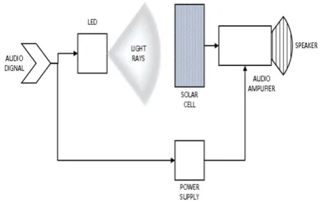
Fig. 2 shows the block diagram which consists of an input audio signal which is fed to the LED (light emitting diode) block, which is the transmitter. The receiving section consists of solar cell block which receives the encoded signal from the LED in form of transmitted light rays, decodes this signal and feeds it to the amplifier blocks and the speaker.
Figure 2. Power supply block diagram
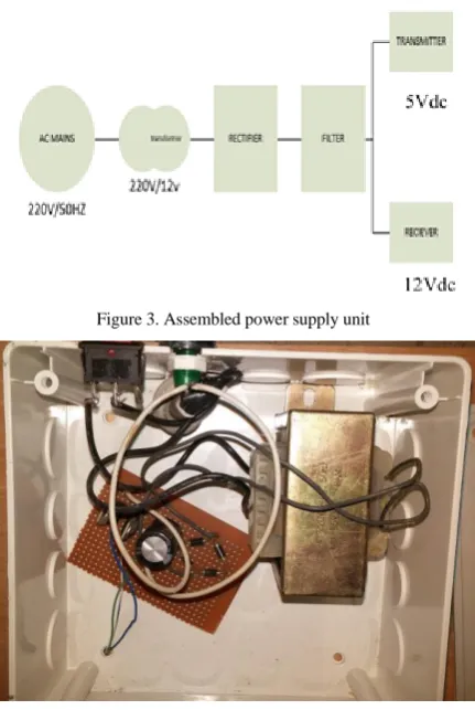
Figure 3. Assembled power supply unit
In reality, transmitters and receivers have their individual power supply, however, for this experimental setup, only one power supply unit was used to power both the transmitter and the receiver as shown in Fig. 3.
15V transformer is used to step down the input AC voltage from 220Vac to a 12Vac; this voltage is fed to the rectification section using 4 1N4007 diode as bridge rectifier to be rectified. The DC voltage is passed through a 2200µf 50volt smoothing capacitor to eliminate ripples, and finally the output voltage is divided into two tapping through two voltage regulators, LM7812 and LM7805. The LM7805 serves as the supply to the transmitter while LM7812 servers as the supply to the receiver. Also integrated into the power supply is a switch and also an indicator lamp.
The step-down transformer is used to step down the 220VAC to 12Vdc and rectified using a bridge rectifier (1*4 IN4007 diode). A smoothing capacitor is used to remove the leftover AC ripples after rectification [8].
Vripple = 1.4 × Vinput = 1.4 x 12V = 16.8V (1)
Voltage regulators 7805 and 7812 were specifically used to regulate the output voltages of the transmitter and receiver to 5V and 12V, respectively.
B. Transmitter Design
The transmitter section consists of a 3.5mm audio connector that serves as data input source, and 3 LED light bulbs that serve as 3 transmitters. The receiver section consists of 3 solar cells that serve as photodetector. The solar cells measure 110x69mm, with a voltage rating of 5V and power rating of 1.2W, with an excellent weak light effect that can detect very faint beams. Also, at the receiver section is a low voltage amplifier LM386 amplifier that produced a voltage gain of 1.355.
Output Voltage (Receiver output) =12.06V (2) Input Voltage (Transmitter) = 8.9V (3)
Using the following formula [8]:
Voltage Gain (Av) = Vout / Vin (4) Voltage Gain (Av) = 12.06 V/8.9V = 1.355 (5)
The transmitters consist of a 3.5mm audio jack and LED(s). The 3.5mm audio jack sends the signal from the signal generator or ‘audio source’ and transmits it through the LEDs. The LEDs are placed in a curved shape reflector, as shown in Fig. 4, to reflect the light rays in a particular direction, in this case, towards the photodetector. The curved shape of the reflector ensures a full beam of light is concentrated in one direction and are less dispersed. The transmitter voltage output was 8.9V, which was regulated to 5Vdc using the LM7805 voltage regulator (see Fig. 5).
Figure 4. Transmitter
C. Receiver Design
The receiver section is made up of the amplifier (LM358), the speaker (1 watt) and the photo detector (Solar cells). The photo detector detects the signal from the LEDs and sends it as an input to the amplifier to be processed, after which the output is sent to the speaker.
Figure 6. Amplifier circuit after assembly
Figure 7. Transmitter showing photodetector (solarpanel) and speaker
Figure 8. Receiver voltage measurement
The receiver output voltage was 12.06V, which was regulated to 12Vdc using the LM7812 voltage regulator (see Fig. 8).
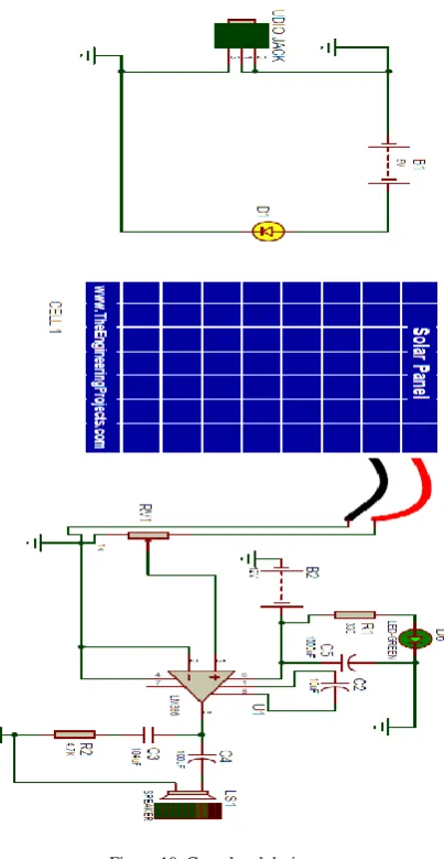
Figure 9. Combined circuit diagram of Li-Fi transmitter and receiver
Figure 10. Completed design
D. Transmitter Operation
E. Receiver Operation
Solar panels can detect small intensity changes and correspondingly, there is change in the voltages at output of solar panel. So, when the beam from the LED is cast on the panel, voltages will vary according to the intensity of light. The voltage of solar panel is fed into amplifier (Speaker) which amplifies the signal and in turn, sends the audio output through the speaker connected to the amplifier.
Output will be produced as long as solar panel maintains line of sight with LED and a clearer audio output can be achieved within the 15-20cm range. Greater distances can be achieved by increasing the area of solar panel and the wattage of the LED.
F. Transmission Test
The design was tested using a mobile phone as the signal generator to transmit sound through all three LEDs. All speakers produced sound transmitted from the signal generator through the LEDs (see Fig. 11). In Fig. 12 and 13, the test was repeated by placing an opaque object between the photodetector and one, and two LED, respectively, and it was discovered that there was sound output only on the receivers without an obstacle. Similar results were also achieved when an opaque obstacle blocked off all three receivers.
Figure 11. Sound transmission on all LEDs
Figure 12. Transmission test with interference on one LED
Figure 13. Transmission test with interference on two LEDs
III. RESULTSANDDISCUSSION
The transmission test shows that the LEDs must maintain line of sight communication with the photodetector in order for transmission to take place and obstacles along the line of sight can cause a break in transmission. This means that there must be a complete coverage of the Li-Fi environment, and only mobile users within the room where a Li-Fi network is deployed can have access to the Li-Fi network. Hence, this eliminates the possibility of malicious interception of data during transmission; a problem which persists with Wi-Fi communication.
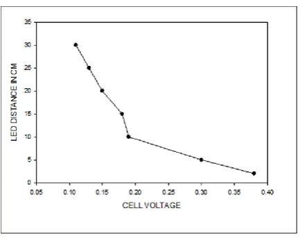
The Solar Voltage Test also reveals that the strength of transmission reduces as a mobile user moves away from the transmitter. This means that users must stay within the range specified in the network design for effective communication with the transmitter. Furthermore, ambient light needs to be minimized or even eliminated for effective and quality data transmission on the network.
Figure 15. Graph of distance against cell voltage
integrity and quality of data being transmitted reduces with increasing distance between the transmitter and the photodetector.
CONCLUSION
From the design and simulation stages to the construction and implementation, it can be seen that the work has successfully demonstrated the workability of a wireless data transmission through LED light bulbs. This also means that Visible Light Communication provides an environmentally friendly alternative to radio frequency. Light Fidelity provides a more secure means of data communication than other technologies like Wi-Fi. From the tests conducted, an opaque obstacle totally cuts off communication between a transmitter and receiver; hence, communication on a Li-Fi network cannot easily be intercepted. However, as much as this is an advantage, it also poses a limitation to its deployment in certain places, like parks, school premises and other public places.
In this purview, in order to achieve a full coverage, Wi-Fi can be deployed alongside Li-Fi to cover areas outside Li-Fi coverage.
This work can be improved upon by amplifying the signal using components with higher capacity to enable the amplified signal to travel farther. Future designs should accommodate range upwards of 10ft between transmitter and receiver. Another area of improvement is the development of wearable
devices like headphones that can serve as the receivers. This will make it suitable for use in conferences, airports, cinemas and other public places where noise level should be kept under control.
REFERENCES
[1] Statista, "Internet of Things - number of connected devices worldwide 2015-2025," 2019. [Online]. Available: https://www.statista.com/statistics/471264/iot-number-of-connected-devices-worldwide/.
[2] Techopedia, "Spectrum Crunch," 2019. [Online]. Available: https://www.techopedia.com/definition/29483/spectrum-crunch.
[3] S. Anurag, N. Asoke and A. Shalabh, "Li-Fi Technology: Data Transmission through Visible Light," International Journal of Advance Research in Computer Science and Management Studies, vol. volume 3, no. issues 6, 2015. [4] H. Haas, "TEDGlobal," 2011. [Online]. Available:
https://www.ted.com/talks/harald_haas_wireless_data_from_ every_light_bulb?language=en.
[5] J. Papiewski, "Which Wavelengths and Frequencies Are Most Dangerous?," 2018. [Online]. Available: https://sciencing.com/wavelengths-frequencies-dangerous-7487438.html.
[6] M. Islim and H. Haas, "Modulation Techniques for Li-Fi," ZTE Communications, vol. 14, no. 2, pp. 29-40, 2016. [7] S. Yaklaf and K. Tarmissi, "Multi-Carrier Modulation
Techniques for Light Fidelity Technology," Sousse, 2019. [8] P. Elechi, “Design and Development of Sound Control Door