DET
NORSKE
VERITAS
AS
The content of this service document is the subject of intellectual property rights reserved by Det Norske Veritas AS (DNV). The user accepts that it is prohibited by anyone else but DNV and/or its licensees to offer and/or perform classification, certification and/or verification services, including the issuance of certificates and/or declarations of conformity, wholly or partly, on the basis of and/or pursuant to this document whether free of charge or chargeable, without DNV's prior written consent. DNV is not responsible for the consequences arising from any use of this document by others.
The electronic pdf version of this document found through http://www.dnv.com is the officially binding version
DNV
STATUTORY INTERPRETATIONS
to operate and a competitive advantage. Our core competence is to identify, assess, and advise on risk management. From our leading position in certification, classification, verification, and training, we develop and apply standards and best practices. This helps our customers safely and responsibly improve their business performance. DNV is an independent organisation with dedicated risk professionals in more than 100 countries, with the purpose of safeguarding life, property and the environment.
© Det Norske Veritas AS September 2013
Any comments may be sent by e-mail to [email protected]
If any person suffers loss or damage which is proved to have been caused by any negligent act or omission of Det Norske Veritas, then Det Norske Veritas shall pay compensation to such person for his proved direct loss or damage. However, the compensation shall not exceed an amount equal to ten times the fee charged for the service in question, provided that the maximum compensation shall never exceed USD 2 million.
CHANGES – CURRENT
General
This document supersedes DNV Statutory Interpretations, February 2013.
Text affected by the main changes in this edition is highlighted in red colour. However, if the changes involve a whole chapter, section or sub-section, normally only the title will be in red colour.
Main changes coming into force 1 March 2014
• SOLAS Ch.II-2 - Construction – Fire Protection, Fire Detection and Fire Extinction, FSS Code,
IMSBC Code
— SOLAS II-2/10.6; Sub-title “Fire-extinguishing arrangements in control stations, accommodation and service spaces” has been added and first part of reg. 10.6.1 has been deleted in line with revised US Cost Guard requirements.
• FSS Code Ch.5 Fixed Gas Fire-extinguishing Systems
— In “General requirements for CO2 Fire-Extinguishing Systems”, two paragraphs have been added under FSS Code Ch.5.2.2.
• SOLAS Ch.III: Lifesaving Arrangement, LSA Code
— In general the text has been edited in order to improve readability.
— In SOLAS III/4&5 a) terminology and process for internal communication equipment not holding DNV type approval certificate have been modified.
— In SOLAS III 6.4.1 the paragraph has been restructured and the text edited.
— A new paragraph for integrated Public Address and General Alarm Systems has been included with interpretations on SOLAS III 6.4.2.
— In SOLAS III 6.4.3 precautions towards failure in the General Alarm Systems and specification of Normal crew working space has been added.
— New paragraphs dealing with public address systems in SOLAS 6.5.3.1 and 6.5.3.2 for special purpose ships > 60 persons and in MSC/Circ.808 have been added.
• SOLAS Ch.IV: Radio Communications Global Maritime Distress and Safety System (GMDSS)
— In SOLAS IV/16 it has been clarified that 2 holders of general operators’ certificate with regard to GMDSS are required.
• Appendix A Test Program and Acceptance Criteria for Water Mist Sprinkler System Fitted in
Accommodation and Service Spaces
— In Part 5, the flowchart has been extended with a new textbox stating numbers of sprinklers to be tested in each section for Extended testing case i.
In addition to the above stated main changes, editorial corrections may have been made.
CONTENTS
CHANGES – CURRENT ... 3 INTRODUCTION... 7 1 General... 7 1.1 Objective ... 7 1.2 The Society ... 7 1.3 Statutory Certification... 7 1.4 Definitions... 7 1.5 Restricted use ... 72 Applicable Statutory Requirements... 7
2.1 Application... 7
2.2 IACS Unified Interpretations (IACS UIs) ... 7
2.3 Amendments and adoption ... 7
SOLAS INTERPRETATIONS... 8
SOLAS Ch. II-1: Construction ... 9
General... 9
Documentation Requirements ... 9
SOLAS II-1/3-5 New installation of materials containing asbestos ... 9
SOLAS II-1/3-9 Means of Embarkation on and Disembarkation from Ships ... 9
SOLAS Ch. II-2: Construction – Fire Protection, Fire Detection and Fire Extinction, FSS Code, IMSBC Code ... 10
General... 10
Documentation Requirements ... 10
SOLAS II-2/3 Definitions ... 13
SOLAS II-2/5 Fire Growth Potential ... 13
Control of air supply and flammable liquid to the space... 13
Fire protection materials ... 14
SOLAS II-2/6 Smoke Generation Potential and Toxicity ... 14
Paints, varnishes and other finishes, primary deck coverings ... 14
SOLAS II-2/7 Detection and Alarm ... 14
Requirements of the FSS Code Ch.9 Fixed fire detection and fire alarm systems... 14
SOLAS II-2/8 Control of Smoke Spread ... 14
Protection of control stations outside machinery spaces ... 14
SOLAS II-2/9 Containment of Fire ... 14
Thermal and structural boundaries ... 14
Protection of openings in fire-resisting divisions ... 16
Protection of openings in machinery space boundaries... 16
Ventilation systems... 16
SOLAS II-2/10 Fire Fighting ... 16
Water supply systems ... 16
Portable fire extinguishers ... 17
FSS Code Ch.4.3 Engineering specifications ... 17
Fixed fire-extinguishing systems ... 17
Fire-extinguishing arrangements in machinery spaces... 17
Fire-extinguishing arrangements in control stations, accommodation and service spaces... 17
Fire-extinguishing arrangements in cargo spaces... 18
Fire-fighter’s outfits... 18
SOLAS II-2/13 Means of Escape ... 18
Means of escape from control stations, accommodation spaces and service spaces... 18
Means of escape from machinery spaces... 20
Means of escape from ro-ro spaces... 21
Additional requirements for ro-ro passenger ships... 22
FSS Code Ch.13 Arrangements of means of escape ... 22
SOLAS II-2/14 Operational readiness and maintenance ... 22
Operational Requirements ... 22
SOLAS II-2/15 Instructions, Onboard Training and Drills... 30
Fire Control Plan... 30
SOLAS II-2/18 Helicopter Facilities... 30
Structure... 30
Fire-fighting appliances ... 31
Helicopter refuelling and hangar facilities... 31
SOLAS II-2/19 Carriage of Dangerous Goods ... 31
General... 31
Ventilation ... 31
Fans to be of a type that prevents the possibility of the ignition of flammable gas-air mixtures... 31
Wire mesh guard for ventilation openings... 31
Equivalent protection to wire mesh guards may be spark arresting screens ... 31
Portable fire extinguishers ... 32
Equivalencies to dry powder... 32
Document of Compliance ... 32
The International Maritime Solid Bulk Cargoes (IMSBC) Code ... 32
Substances which may self-heat ... 32
Substances which shall not be stowed on or adjacent to heated surfaces... 32
SOLAS II-2/20 Protection of Vehicle, Special Category and Ro-Ro Spaces ... 32
Precaution against ignition of flammable vapours in closed vehicle spaces, closed ro-ro spaces and special category spaces ... 32
SOLAS II-2/21 Casualty Threshold, Safe Return to Port and Safe Areas and SOLAS II-2/22 Design criteria for systems to remain operational after a fire casualty ... 33
Application... 33
Navigational systems ... 33
FSS Code Ch.5 Fixed Gas Fire-extinguishing Systems ... 33
General requirements for all Gas Fire-extinguishing Systems ... 33
General requirements for CO2 Fire-Extinguishing Systems ... 35
Fire-extinguishing systems for cargo holds... 36
CO2 high pressure fire-extinguishing systems for machinery spaces, cargo handling spaces and ro-ro spaces 36 Low Pressure CO2 Systems ... 37
Equivalent Fixed Gas Fire Extinguishing Systems ... 38
FSS Code Ch.6 Fixed Foam Fire Extinguishing Systems... 38
General requirements to High Expansion and Inside Air Foam Systems... 38
SOLAS Ch. III: Lifesaving Arrangement, LSA Code ... 42
General... 42
Documentation requirements ... 42
Passenger Ships and Cargo Ships... 43
SOLAS III/3 Definitions... 43
SOLAS III/4 Evaluation, testing and approval of life-saving appliances and arrangements, and SOLAS III/5 Production tests... 43
SOLAS III/6 Communications ... 43
SOLAS III/7 Personal life-saving appliances... 45
SOLAS III/11 Survival craft muster and embarkation arrangements... 45
SOLAS III/13 Stowage of survival craft ... 45
SOLAS III/16 Survival craft launching and recovery arrangements... 46
SOLAS III/17 Rescue boat embarkation, launching and recovery arrangements ... 46
SOLAS III/21 Survival craft and rescue boats ... 46
SOLAS III/22 Personal life-saving appliances... 46
Cargo Ships (Additional Requirements)... 46
SOLAS III/31 Survival craft and rescue boats ... 46
SOLAS III/32 Personal life-saving appliances... 47
SOLAS III/33 Survival craft embarkation and launching arrangements... 47
Life-saving Appliances and Arrangements Requirements (LSA-Code) ... 47
LSA-Code Ch.IV, Regulation 4.7 Free-fall lifeboats ... 47
LSA-Code Ch.VI Launching and embarkation appliances ... 47
SOLAS Ch. IV: Radio Communications Global Maritime Distress and Safety System (GMDSS) ... 48
Document requirements ... 48
SOLAS IV/6 - Radio Installations... 48
SOLAS IV/7 - Radio equipment - General... 48
SOLAS IV/13.3 - Sources of Energy... 49
SOLAS IV/15 - Maintenance Requirements ... 49
SOLAS IV/16 - Radio Personnel... 49
SOLAS Ch. V: Safety of Navigation... 50
Documentation requirements ... 50
SOLAS V/18 Approval, surveys and performance standards of navigational systems and equipment and voyage data recorder ... 50
SOLAS V/19 Carriage requirements for shipborne navigational systems and equipment ... 50
SOLAS V/23 Pilot ladder arrangements... 51
SOLAS V/28 Records of navigational activities and daily reporting... 51
SOLAS Ch. IX: Management for the Safe Operation of Ships, ISM Code ... 52
5 Master's responsibility and authority ... 52
12 Company verification, review and evaluation... 52
Resolution A.1022(26) Guidelines on the Implementation of the International Safety Management (ISM) Code by Administrations... 52
3 The Certification Process... 52
SOLAS Ch. XI-2: Special Measures to Enhance Maritime Security ... 53
SOLAS XI-2/6 Ship Security Alert System ... 53
App. A Test Program and Acceptance Criteria for Water Mist Sprinkler System Fitted in Accommodation and Service Spaces ... 54
A.1 Introduction ... 54
A.2 Basic testing ... 54
A.3 Extended testing ... 54
Part 1 – acceptance criteria basic testing... 54
Part 2 – water samples... 55
Part 3 – acceptance criteria extended testing ... 55
Part 4 – replacing of all sprinklers ... 55
Part 5 – flowchart to describe main items of the test procedure ... 56
INTRODUCTION
1
General
1.1
Objective
1.1.1 This publication presents the Society's interpretations of international statutory instruments. Such interpretations may be on matters which are left to the satisfaction of the flag administration or are vaguely worded. Interpretations described in this publication, are given in those circumstances where IACS Unified Interpretations (UIs) or no other interpretations exist.
1.1.2 This publication covers only selected relevant topics and shall under no circumstances be taken as the Society's complete interpretations to international statutory instruments.
1.2
The Society
1.2.1 See DNV Rules for Classification of Ships (“the Rules”) Pt.1 Ch.1 Sec.1 A.
1.3
Statutory Certification
1.3.1 The Society undertakes statutory certification on behalf of flag administrations when and to the extent the Society has been authorised to do so by the individual flag administration. Statutory certification includes inter alia approval, survey and the issuance of statutory certificates. See further the Rules Pt.1 Ch.1 Sec.1 D.
1.3.2 When statutory certification is undertaken, the document requirements for approval and the survey requirements are based on IMO resolution A.997(25), Survey Guidelines under the Harmonized System of Survey and Certification, 2007, as amended, unless otherwise specified in this publication. The IMO guideline is also applied as applicable for the HSC Code and the MODU Code.
1.3.3 For general requirements to documentation, including definition of the Info codes, see the Rules Pt.0 Ch.3 Sec.1, and for a full definition of the documentation types, see the same rule chapter Sec.2.
1.4
Definitions
1.4.1 See the Rules Pt.1 Ch.1 Sec.1 A.
1.5
Restricted use
1.5.1 These Statutory Interpretations are under the sole ownership rights and copyrights of the Society. It is prohibited by anyone else than the Society to offer and/or perform classification, certification or verification services including issuance of certificates and/or declarations of conformity, wholly or partly, on the basis of and/or pursuant to these interpretations without the Society's prior written consent. The Society is not responsible for the consequences arising from any use of these interpretations by others.
2
Applicable Statutory Requirements
2.1
Application
2.1.1 When the Society acts on behalf of a flag administration, the Society follows international statutory instruments, IACS Unified Interpretations and DNV Statutory Interpretations, and generally follows guidance issued by IMO in Circulars etc. unless the flag administration has instructed the Society otherwise.
2.2
IACS Unified Interpretations (IACS UIs)
2.2.1 An overview and the text of all IACS UIs are given on IACS homepage, http://www.iacs.org.uk/ and in the IMO-Vega database that can be ordered through IMO or DNV.
2.3
Amendments and adoption
2.3.1 New and amended SI's shall be applied from 6 months after date of publishing, unless otherwise noted. Interpretations shall however only be applied for vessels where the relevant part of the convention or code is in force.
SOLAS INTERPRETATIONS
CONTENTS
PAGE
SOLAS Ch. II-1: Construction ... 9
SOLAS Ch. II-2: Construction – Fire Protection,
Fire Detection and Fire Extinction, FSS Code, IMSBC Code... 10
SOLAS Ch. III: Lifesaving Arrangement, LSA Code ... 42
SOLAS Ch. IV: Radio Communications
Global Maritime Distress and Safety System (GMDSS)... 48
SOLAS Ch. V: Safety of Navigation... 50
SOLAS Ch. IX: Management for the Safe Operation of Ships, ISM Code... 52
SOLAS Ch. XI-2: Special Measures to Enhance Maritime Security ... 53
App. A Test Program and Acceptance Criteria for Water Mist Sprinkler System Fitted in
Accommodation and Service Spaces... 54
SOLAS CH. II-1: CONSTRUCTION
General
For non-propelled vessels or cargo vessels with a tonnage of less than 500 (length of less than 24 meters regarding load line), IACS Rec. No. 99 or national requirements may be applied for issuance of safety certificates. For such units, an MO will be issued identifying the standard applied.
Documentation Requirements
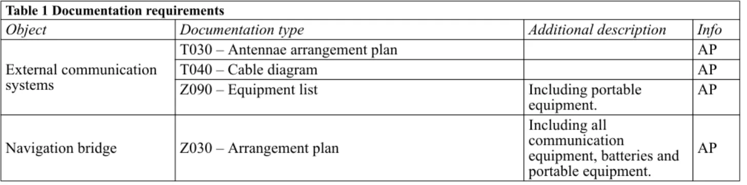
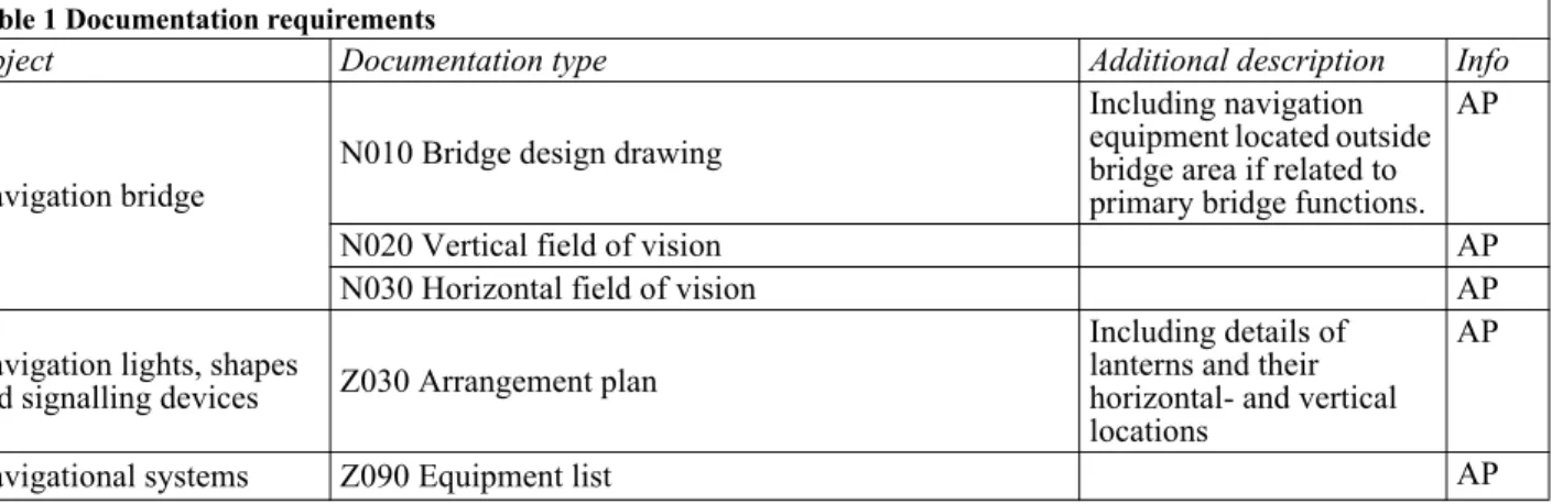
For cargo vessels of 500 gross tonnage and above when the government of the flag state has authorised the Society to issue the SOLAS safety construction certificate (CCC) on their behalf, documentation shall be submitted according to Table 1:
SOLAS II-1/3-5 New installation of materials containing asbestos
DNV will apply IACS Unified Interpretation SC 249 and review declarations documenting that relevant new installations are asbestos-free as part of annual survey of the safety construction certificate (or equivalent certificate).
Missing declarations is not in itself considered a finding according to the convention, but if there is evidence that the procurement is not sufficiently controlled, DNV will notify the issuer of the Safety Management Certificate in accordance with IACS PR17.
SOLAS II-1/3-9 Means of Embarkation on and Disembarkation from Ships
MSC Circ.1331 shall be followed to obtain compliance with requirements in Regulation 3-9. For Newbuildings, i.e. vessels constructed on or after 1 January 2010:DNV product certificate is required for gangways and accommodation ladder including its winch.
Small freeboard:
Vessels with small freeboard may be exempted from carrying gangways or accommodation ladders. Exemptions will from case to case be based on decision made by the flag administration.
Boarding ramp:
A boarding ramp is a gangway with less than 2 meters length.
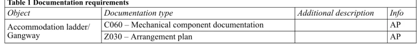
Table 1 Documentation requirements
Object Documentation type Additional description Info
Accommodation ladder/ Gangway
C060 – Mechanical component documentation AP
SOLAS CH. II-2: CONSTRUCTION – FIRE PROTECTION,
FIRE DETECTION AND FIRE EXTINCTION, FSS CODE, IMSBC CODE
General
For non-propelled vessels or cargo vessels with a tonnage of less than 500, IACS Rec. No. 99 or national requirements may be applied for issuance of safety certificates. For such units, an MO will be issued identifying the standard applied.
Documentation Requirements
For cargo vessels of less than 500 gross tonnage assigned main class and which are in line with IACS IG2 for ships with unrestricted service, documentation shall be submitted according to Table 1:
For fire safety component and systems, the following shall be submitted for approval or review: — copies of the DNV type approval certificates, or
— fire test reports for the constructions and equipment which shall be used onboard, or — type approval certificate issued by flag state (including MED as applicable).
For cargo vessels of 500 gross tonnage and above assigned main class, documentation shall be submitted according to Table 2:
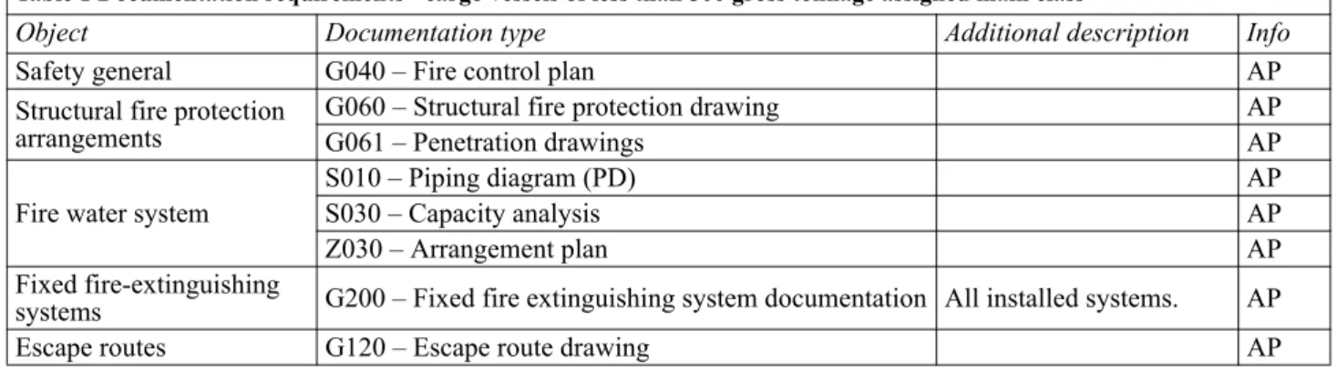
Table 1 Documentation requirements - cargo vessels of less than 500 gross tonnage assigned main class
Object Documentation type Additional description Info
Safety general G040 – Fire control plan AP
Structural fire protection
arrangements G060 – Structural fire protection drawingG061 – Penetration drawings APAP
Fire water system
S010 – Piping diagram (PD) AP
S030 – Capacity analysis AP
Z030 – Arrangement plan AP
Fixed fire-extinguishing
systems G200 – Fixed fire extinguishing system documentation All installed systems. AP
Escape routes G120 – Escape route drawing AP
Table 2 Documentation requirements - cargo vessels of 500 gross tonnage and above assigned main class
Object Documentation type Additional description Info
For cargo vessels of 500 gross tonnage and above when the government of the flag state has authorised the Society to issue the Cargo Ship Safety Construction Certificate (CCC) and the Cargo Ship Safety Equipment Certificate (CEC) on their behalf, documentation shall be submitted according to Table 3:
For constructions and equipment required by SOLAS to be tested in accordance with the Fire Test Procedure Code, the following applies:
— copies of the certificates of approval and fire test reports for the equipment that shall be used onboard, but which have not been approved by the Society or the government of the flag state, shall be submitted for approval.
For passenger vessels of 500 gross tonnage and above when the government of the flag state has authorised the Society to issue the Passenger Ship Safety Certificate (PSSC) on their behalf, documentation shall be submitted according to Table 4:
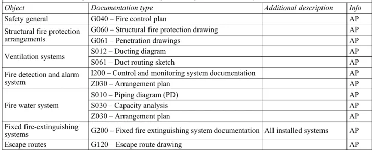
Table 3 Documentation requirements - vessels of 500 gross tonnage and above, Society authorised to issue CEC and CCC
Object Documentation type Additional description Info
Safety general G040 – Fire control plan AP
Structural fire protection arrangements
G060 – Structural fire protection drawing AP
G061 – Penetration drawings AP
Ventilation systems S012 – Ducting diagram AP
S061 – Duct routing sketch AP
Fire detection and alarm system
I200 – Control and monitoring system documentation AP
Z030 – Arrangement plan AP
Fire water system
S010 – Piping diagram (PD) AP
S030 – Capacity analysis AP
Z030 – Arrangement plan AP
Fixed fire-extinguishing
systems G200 – Fixed fire extinguishing system documentation All installed systems AP
Escape routes G120 – Escape route drawing AP
Table 4 Documentation requirements – passenger vessels of 500 gross tonnage and above, Society authorised to issue PSSC.
Object Documentation type Additional description Info
Safety general G040 – Fire control plan AP
Fire resisting and
non-combustible materials M020 – Material specification, fire related properties
Surface materials, insulation materials, primary deck coverings, textiles, furniture and bedding.
AP Structural fire protection
arrangements G060 – Structural fire protection drawingG061 – Penetration drawings APAP
Fire doors control and
monitoring system I200 – Control and monitoring system documentation AP
Fire detection and alarm system
I200 – Control and monitoring system documentation AP
Z030 – Arrangement plan AP
Fire water system
S010 – Piping diagram (PD) AP
S030 – Capacity analysis AP
Z030 – Arrangement plan AP
Fixed fire-extinguishing
systems G200 – Fixed fire extinguishing system documentation AP
Emergency escape G100 – Escape and evacuation study AP
Escape routes G120 – Escape route drawing AP
Ventilation systems S012 – Ducting diagram AP
S061 – Duct routing sketch AP
Low location lights E190 – Lighting description AP
For passenger vessels that shall comply with SOLAS II-2/21 and 22 regarding Safe Return to Port (SRtP), documentation shall be submitted according to Table 5:
For constructions and equipment required by SOLAS to be tested in accordance with the Fire Test Procedure Code (FTP Code), the following applies:
— copies of the certificates of approval and fire test reports for the equipment that shall be used onboard, but which have not been approved by the Society or the government of the flag state, shall be submitted for approval.
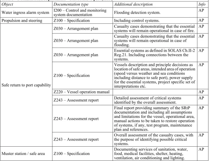
Table 5 – Documentation requirements – Safe return to port (SRtP)
Object Documentation type Additional description Info
Water ingress alarm system I200 – Control and monitoring system documentation Flooding detection system. AP
Propulsion and steering Z100 – Specification Including control systems. AP
Safe return to port capability
Z030 – Arrangement plan Casualty cases demonstrating that the essential systems will remain operational in case of fire. AP Z030 – Arrangement plan Casualty cases demonstrating that the essential systems will remain operational in case of
flooding.
AP
Z030 – Arrangement plan Essential systems as defined in SOLAS Ch.II-2 Reg.21. Including connections between the systems.
AP
Z100 – Specification
Vessels description and principle decisions as location of safe areas, intended area of operation (speed versus weather and sea conditions including distance to safe port), power supply for the essential systems, project specific set of interpretations etc.
AP
Z220 – Vessel operation manual AP
Z243 – Assessment report Detailed assessment of critical systems identified by the overall assessment. AP
Z243 – Assessment report
Final report providing summary of the SRtP documentation and including all assumptions and limitations for the vessel, operational area, manual actions to be taken to restore operation of systems, if any, test program, maintenance plan and references.
AP
Z243 – Assessment report Overall assessment of the casualty cases, with the purpose of identifying possible critical systems.
AP
Muster station / safe area Z100 – Specification Documenting services of sanitation, water, food, medical facilities, shelter, heating, ventilation, air conditioning and lighting.
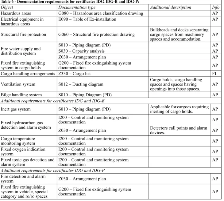
Documents for all cargo vessels and passenger vessels when the government of the flag state has authorized the Society to issue the SOLAS Document of Compliance for the carriage of dangerous goods (IDG, IDG-B and IDG-P) on their behalf, shall be submitted for approval according to Table 6:
SOLAS II-2/3 Definitions
Regulation 3.1
Induction cooking tops with power output up to 5 kW (called “induction heaters” in IMO MSC/Circ.1120, 3.1 sub item 1) are allowed used in pantries and dining rooms.
Regulation 3.31
A space that cannot be entered independently of machinery spaces of category A shall also be regarded as a machinery space of category A.
SOLAS II-2/5 Fire Growth Potential
Control of air supply and flammable liquid to the space
Regulation 5.2.1.2This applies to all ventilation fans (circulation fans included).
Table 6 - Documentation requirements for certificates IDG, IDG-B and IDG-P:
Object Documentation type Additional description Info
Hazardous areas G080 – Hazardous area classification drawing AP
Electrical equipment in
hazardous areas E090 – Table of Ex-installation AP
Structural fire protection G060 – Structural fire protection drawing Bulkheads and decks separating cargo spaces from machinery spaces and accommodation. AP Fire water supply and
distribution system
S010 – Piping diagram (PD) AP
S030 – Capacity analysis AP
Z030 – Arrangement plan AP
Fixed fire extinguishing
system in cargo holds G200 – Fixed fire extinguishing system documentation AP
Cargo handling arrangements Z330 – Cargo list FI
Ventilation system S012 – Ducting diagram Cargo holds, cargo handling spaces and spaces having
openings into those spaces. AP
Bilge handling system S010 – Piping Diagram (PD) AP
Additional requirements for certificates IDG and IDG-B
Inert gas system S010 – Piping diagram (PD) Applicable for cargoes requiring inerting of cargo holds. AP Fixed hydrocarbon gas
detection and alarm system
I200 – Control and monitoring system
documentation AP
Z030 – Arrangement plan Detectors call points and alarm devices. AP Cargo temperature
monitoring system I200 – Control and monitoring system documentation AP
Fixed oxygen indication
system I200 – Control and monitoring system documentation AP
Fixed toxic gas detection and
alarm system I200 – Control and monitoring system documentation AP
Additional requirements for certificates IDG and IDG-P
Fire detection and alarm
system Z030 – Arrangement plan AP
Fixed fire extinguishing system in vehicle, special category and ro/ro spaces
G200 – Fixed fire extinguishing system
Fire protection materials
Regulation 5.3.1Neither combustible nor oil-absorbing materials shall be used as flooring, bulkhead lining, ceiling or deck in the engine control room, machinery spaces, shaft tunnel or rooms where oil tanks are located.
SOLAS II-2/6 Smoke Generation Potential and Toxicity
Paints, varnishes and other finishes, primary deck coverings
Regulation 6.2 and 5.3The first footnote to the table on page 29 in MSC/Circ.1120 is explaining that the term “exposed surfaces” used in regulation II-2/5.3.2.4.1.1 to include the floor coverings. Thus, the requirement for low flame-spread in column (D) in the table will apply to the floor coverings in corridors and stairways and not to the floor coverings in cabins and public spaces.
The term “exposed interior surfaces” in regulation 6.2 is normally interpreted to have the same meaning as “exposed surfaces” mentioned above. However, since the footnote is not indicated for the requirement for smoke and toxic products in column (E) in the table, the smoke and toxicity test for floor coverings in cabins and public spaces are not required.
SOLAS II-2/7 Detection and Alarm
Regulation 7.7
When corridors have two exits to open deck, one manually operated call point is required at each of the exits. Additional manually operated call point at the internal exit to e.g stairway is not required as long as the 20 m distance requirement is not exceeded.
Requirements of the FSS Code Ch.9 Fixed fire detection and fire alarm systems
FSS Code Ch.9.2.1.1When it is intended that a particular section or detector shall be temporarily switched off, this state shall be clearly indicated. Reactivation of the section or detector shall be performed automatically after a preset time.
FSS Code Ch.9.2.3.1
When fire detectors are provided with the means to adjust their sensitivity, necessary arrangements shall be ensured to fix and identify the set point.
SOLAS II-2/8 Control of Smoke Spread
Protection of control stations outside machinery spaces
Regulation 8.2As equally effective means, in case of ventilators these shall be fitted with steel dampers which shall be easily closed within the control station in order to maintain the absence of smoke in the event of fire.
SOLAS II-2/9 Containment of Fire
Thermal and structural boundaries
Regulation 9.2.2.3.2.2In addition to electrical distribution boards, PA/audio-racks/DVD-players and similar electronic equipment may also be located behind panels/lining within accommodation subject to the following:
— If located in an identifiable space having a deck area of less than 4 m2, this space is to be categorized as (7)
and be protected by smoke detectors and sprinklers. An identifiable space will normally be an enclosure which can be walked into, with equipment accessed from inside the space.
— If not located in an identifiable space but in an extended enclosure behind panels/lining, served from the panel side, this enclosure is to be protected by smoke detectors. This should be the typical situation for audio/video racks and distribution boards arranged in the open behind panels/lining.
Regulation 9.2.2.3.2.2
If two areas shall be treated as a common space the opening between these spaces shall be at least 30% and the openings shall be communicating openings and permanent. Windows/glass is not considered to be communicating openings which contribute to the 30% open requirement.
(5) Storage of petrol (e.g. for marinas and water-scooter) is accepted on open decks.
(8) Steam Rooms: If the amount of combustible materials exceeds what is specified in SOLAS II-2/5.3.2 the steam rooms to be treated as sauna with respect to fire protection.
Slop chest like a normal shop where crew go in, grab what they want and pay on the way out. (9) steam power pack/systems less than 5kW less and located inside the steam room.
(11) Cold Stores/refrigerated spaces shall have a temperature below +5°C. (13) steam power pack exceeding 5 kW
Slop chest of a “store type” where there is a counter where crew ask what they want and the keeper takes the item(s) from the shells and bring it (them) to the “customer”, like in the hotel stores or machinery stores etc.
(14) Class I and class II liquids according to NFPA Fire Protection Handbook, shall be considered as flam-mable liquids. Class I liquids have flash points below 100°F (37.8°C) and vapour pressures not exceed-ing 40 psia at 100°F (37.8°C). Class II liquids have flash points at or above 100°F (37.8°C) and below 140°F (60°C).
(14) For not portable fuel tanks the requirements in II-2/18.7 of SOLAS shall be applied. Table 9.2
It is not considered reasonable to apply the superscript “a” relaxation for the deck between two galleys. Therefore a C-class deck will not be accepted between two galleys. Either the deck shall be of class “A-30” according to Table 9.2 or the deck shall be (at least 30%) open to provide one galley space on two deck levels.
Regulation 9.2.3.3.2
(1) Navigation equipment room (radio transmitter). Battery rooms. (Requirements for location of the emer-gency source of electrical power are further given in the Rules Pt.4 Ch.8 Sec.2 C.)
(5) Provision chambers shall be treated as store rooms. Refrigerated provision chambers are considered as category (5) service spaces if thermally insulated with non-combustible materials.
(7) Electrical equipment rooms (auto telephone exchange, air conditioning duct spaces).
(10) Open deck are those spaces which have permanent openings towards open deck of not less than 30% of the area of the greatest length of the space or 10% of the area of all vertical sides, whichever is greatest. The space shall be naturally ventilated by permanent openings, which may be part of the calculated openings above, to ensure that smoke are not accumulated.
1. When calculating 30% permanent openings against open deck the following procedure is to be used: 1.1. The greatest length of the room shall be considered as basis for calculating the required size of the opening(s), this is not necessarily a bulkhead adjacent to the open deck.
1.2. If the permanent opening(s) are not located in the bulkhead of greatest length, openings may be located in one of the shorter bulkheads. In addition, at least 20% of the required size of openings shall then be installed in the bulkhead opposite to the bulkhead where the main openings are installed, or in the side bulkheads. Openings located in the side bulkheads shall then be located such that they are closer to the opposite bulkhead than to the bulkhead where the main opening(s) are provided. Preferably the additional openings shall be located as close to the opposite bulkhead as possible.
1.3. Openings should be located as high in the bulkheads as possible.
1.4. In a room where only one of the shorter bulkheads are provided with permanent openings, and it is not possible to install at least 20% of the required openings in opposite or side bulkheads as required above, the room can not be considered as open deck and have to be assigned a category other than 10.
Table 9.5 Footnote d):
A galley next to a provision room requires an “A-0” bulkhead. Table 9.5 to 9.8
Footnote *
DNV interprets the requirements to openings in way of emergency generator room to apply to both air intakes and outlets.
Protection of openings in fire-resisting divisions
Regulation 9.4.1.2Light fixtures inserted in class B-15 ceiling panels shall in general be made of metal. Plastic materials or other combustible materials are not accepted. In general, any opening shall be arranged to maintain the class B-15 integrity and insulation. This will imply that class B-15 “boxes” shall be made to cover any holes and openings for light fixtures. Smaller openings, e.g. for single spotlights with diameter of 80 mm or less, may be accepted without the B-15 box.
Regulation 9.4.2.2
Hold back arrangements with remote release are not accepted in engine room boundaries.
Regulation 9.4.2.4
Watertight doors in fire-resisting divisions shall be made of steel.
Protection of openings in machinery space boundaries
Regulation 9.5Hatches giving access to the engine room for the transport of goods shall be weather-tight. Where remote control for closing of the hatch is not provided, a signboard to the effect that the hatch-cover shall be closed at all times, except during transfer of goods, shall be posted.
Ventilation systems
Regulation 9.7.1.2.2The regulation should be practised with “or equivalent” at the end of the sentence. One equivalent solution is joining of 200/900 mm long steel sleeves of 3 mm thickness through “A” class divisions to Spiro ducts by means of inserting short linings/ nipples into each end of the steel sleeves onto which the Spiro ducts are drawn, and with the connection sealed with aluminium tape to make it air tight, shall be accepted by DNV as equivalent to tested ventilation duct penetrations if the Spiro ducts are adequately supported with solid clamps/hangers/ supports, which will ensure that the linings/nipples and Spiro ducts can not be dislocated.
Regulation 9.7.3.1.2
The fire dampers should be easily accessible as well as prominently and permanently marked. Where they are placed behind ceilings or linings, these latter should be provided with an inspection door on which a plate reporting the identification number of the fire damper. Such plate and identification number should be placed also on any remote control required.
The indicator may be located behind panel. The indication should be “true indication”.
Regulation 9.7.3.2
Thin steel ducts will be accepted without additional steel sleeve. If a steel sleeve is installed, the sleeve may be of thin steel sheet of thickness not less than 0.5 mm.
Regulation 9.7.5.1
The requirements applies to any exhaust duct serving open galley equipment from which grease can be expected to enter the exhaust, e.g. galley ranges, fryers, deep-fat cooking equipment. Non-greasy branches which are branched from the greasy exhaust should be provided with a fire damper. The duct part between the damper and the connection to the greasy duct shall have fixed means of extinguishing and construction and insulation according to Regulation 9.7.2.1.2.1 and 9.7.2.1.2.2.
Regulation 9.7.5.1.1
As there is no available IMO documentation which provide guidance to “alternative approved grease removal system” per today, the system will be evaluated on a case-by-case basis based on the manufacturers recommendations and specification e.g. UV filters and steam system.
SOLAS II-2/10 Fire Fighting
Water supply systems
Regulation 10.2.1.5.1
When calculating the number of hydrants, the length of the water jet shall be taken as maximum 7 m.
Regulation 10.2.1.6
Regulation 10.2.2.3.2.2 Guidance note:
See the Rules Pt.4 Ch.8 Sec.2 for requirements for cables to remain operable during a fire condition.
---e-n-d---of---G-u-i-d-a-n-c-e---n-o-t-e---Portable fire extinguishers
Regulation 10.3.2.1In vessels of less than 1000 gross tonnage, at least three portable fire extinguishers shall be provided.
Regulation 10.5
50 kg dry powder or 45 kg CO2 is considered as equivalent to 135 l foam liquid. 25 kg dry powder or 20 kg CO2 is considered as equivalent to 45 l foam liquid.
FSS Code Ch.4.3 Engineering specifications
The fire-extinguishing medium in the extinguishers shall be suitable for the potential fire hazards in the protected spaces.
Fixed fire-extinguishing systems
Regulation 10.4On completion, the system shall be function tested. Detailed requirement for high pressure CO2 systems and high--expansion foam system can be found in Sec.2 and Sec.3.
Regulation 10.4.1
— For specific interpretations and clarifications for fixed gas fire-extinguishing systems see Sec.2.
— For specific interpretations and clarifications for fixed high-expansion foam fire-extinguishing systems and equivalent systems (inside air foam) see Sec.3.
Fire-extinguishing arrangements in machinery spaces
Regulation 10.5.1.1Oil fired machinery other than boilers, such as fired inert gas generators, incinerators and waste disposal units shall be considered the same as boilers which requires one of the total fixed fire-extinguishing system required by regulation 10.4.1.1.
Regulation 10.5.2.1
45 l foam extinguisher and foam applicator shall be provided in machinery spaces containing internal combustion machinery, the subject requirement applies only to machinery spaces containing internal combustion machinery used for main propulsion and machinery spaces of category A having more than one platform level.
Fire-extinguishing arrangements in control stations, accommodation and service spaces
Regulation 10.6.1Sprinkler systems in Store room:
Maker’s recommendations to be followed, in addition this applies: Sprinklers should preferably be located in aisles (walkway between shelves), then an air gap of about 100 mm between stored items and deck head is accepted. In case the sprinklers are located above shelves, there should be a 500 mm void below sprinklers (entire area) and this maximum storage height shall be properly marked on bulkheads. For hi-fog nozzles this distance is 300 mm.
Regulation 10.6.4
Deep fat cooking equipment to be any type of fixed cooking appliance that is capable of, and intended to, being filled up with cooking oil.
Tilting frying pans, small portable deep fat fryers (home use type) or traditional electrical galley ranges with flat cooking surfaces are not required to comply with SOLAS Ch. II-2 Regulation 10.6.4.
If small portable deep fat fryers are used, they shall be of a type with lid, with max. capacity 2.5 l and max. power 2.0 kW. These units are only to be used inside the galley boundaries.
Regulation 10.6.4.3
Fire-extinguishing arrangements in cargo spaces
Regulation 10.7Cable reels in enclosed spaces (less than 10% openings in sides + ceiling) shall be provided with a fixed fire extinguishing system. This can be a fire gas extinguishing system if the space can be sealed off in case of a fire or a water spray system designed with 10 litre/minute/m2 of exposed cable reels area for spaces that are not
reasonably gas tight. (Cable reels being handled or stored on open decks or spaces with more than 10% openings in sides and ceiling need not be provided with a fixed fire extinguishing systems.)
Regulation 10.7
Seismic cables containing liquid with flashpoint below 60°C shall be protected by a fixed fire extinguishing system covering the areas where they are stored and handled.
Guidance note:
A suitable fixed fire extinguishing system is a low expansion foam system with the following capacity:
— 3 litre/minute/m2 of streamer deck area
— 10 litre/minute/m2 of cable reels area.
Foam concentrate should be provided for at least 20 minutes of foam generation.
---e-n-d---of---G-u-i-d-a-n-c-e---n-o-t-e---Fire-fighter’s outfits
Regulation 10.10.3
Spare charges for breathing apparatus shall be stored in the same location as the breathing apparatus.
SOLAS II-2/13 Means of Escape
Means of escape from control stations, accommodation spaces and service spaces
Regulation.13.3.2When a room is located inside another room and the escape is into this other room, we have a room-in-room arrangement. Such escape arrangements shall normally be avoided, but may be accepted for small rooms inside galleys (chef's office, bell-box), bedrooms in cabin suites, for casino offices, pantries etc. An additional fire alarm (room-in-room alarm) is to sound inside such isolated rooms upon fire detection in the room outside. A separate drawing should be made by the yard which clearly identifies all room-in-room arrangements.
Regulation.13.3.2
AC rooms are considered only temporarily employed. Hence, two escape ways are required if: 1) The room is more than 50 m2.
2) The room span over two or more decks. At least one escape is required on each deck level.
Regulation.13.3.2
A minimum of two escape routes are required for public spaces and spaces normally manned if the area is 28 m2 or more.
Regulation.13.3.2
Crew working spaces facing open decks which are not normally manned (e.g. AC rooms, deck stores, emergency generator room, lift machinery rooms and similar rooms at upper decks) are accepted to have primary escapes to open decks cat.(5).
Pantries and galleys shall normally have primary escapes directly to corridors and stairways. If part of a primary escape has to cross an open deck, this escape way shall be cat. (4), incl. emergency lighting and anti-slip, minimum width = 1800 mm.
Two escape routes as widely separated as possible to be required from all sun decks and passenger spaces on open decks.
Regulation 13.3.2.1.1
This regulation shall also apply to the means of escape from spaces above the bulkhead deck. At least one means of escape shall be arranged as independent of watertight doors which are assumed closed in order to maintain the weathertight and watertight integrity in the damage stability calculations.
Regulation 13.3.2.4
Designer doors (decorative doors):
— not to interfere physically with fire doors,
— hinged type designer doors are to swing open in escape direction and to have hinge system for staying open when swung to the bulkhead,
— sliding type designer doors with electrical door drive systems shall go to open position and stay in open position upon loss of power, el. fault condition and “close fire doors” status from bridge, if located in escape ways, — sliding type designer doors with electrical door drive systems shall go to open or neutral (manual) position
upon loss of power, el. fault condition and “close fire doors” status from bridge, if not located in escape ways. The sliding doors from stairways to open deck should comply with the last item meaning that it shall be possible to open these doors manually if power is off.
Regulation 13.3.2.4.1
A means of escape required to provide “continuous fire shelter” shall comply with all the requirements applicable for stairways, not only insulation requirements. It applies for all vertical stairways as well as horizontal parts (“horizontal stairways”) of the escape route all the way to the muster/assembly station, being it an indoor or outdoor muster/assembly station.
Regulation 13.3.2.4.2
“protected internal routes” to be understood to be the route from the muster/assembly station to the embarkation area/station deck when the passengers/crew are guided in controlled groups.
Regulation 13.3.2.4.5
FSS Code Ch.13.2.3.1 “doorways and corridors...included in the means of escape shall be sized in the same manner as stairways” does not apply to cabin doors.
Regulation 13.3.3.1
Restricted space or group of spaces in the accommodation:
A Restricted space in the accommodation is understood as a normally employed space within an other space, e.g. a smoker's room at the back of a dining area. For such group of spaces minimum two escape routes are required, see figure 1. Equivalent arrangements will be considered.
Figure 1
Minimum two escape routes required
Storage spaces and similar spaces entered only occasionally are in this context not considered to be normally employed. For such group of spaces minimum one escape route is required, see figure 2.
Dining room
Figure 2
Minimum one escape route required
Cabins consisting of more than one space need also not be provided with more than one escape route.
Regulation 13.3.3.2
The term “lowest open deck” shall be understood as the lowest fire category 10 area (regulation 9.2.3.3.2). This applies regardless of position of accommodation and position of this open deck (forward / aft). Areas of open deck of insignificant area (mooring stations, etc.) can be disregarded.
Regulation 13.3.3.3 and.4
For spaces above the lowest open deck, DNV may on a case by case basis accept trunk or ladders to deck above as means of escape from corridors that otherwise would be considered dead end corridors. This is, however, only accepted if two other means of escape according to Regulation 13.3.3.3 is arranged from one end of such corridor. A window is however not accepted in this regard.
Regulation 13.3.3.4
A dead end corridor is defined as a corridor or part of a corridor from which there is only one escape route.
Means of escape from machinery spaces
Regulation 13.4.2.1Two means of escape is only required from the lowest part of the engine room, not from each level.
Guidance note:
Where the lower part of the engine room is a space with a height lower than 2.3 m (standard deck height for L > 125), the two means of escape may apply to the first deck with standard deck height. The two means of escape do not apply to spaces below the machinery floor plating, regardless of height.
---e-n-d---of---G-u-i-d-a-n-c-e---n-o-t-e---Regulation 13.4.2.1.1
A space is considered a safe position outside the machinery space of category A if it is not contiguous to the boundaries of the machinery space of category A or if the common bulkhead between the two spaces is insulated to class A-60.
Regulation 13.4.2.1.2
If the escape route in the lower part of the space is provided with doors and stairs of adequate size throughout the route, the route will normally be regarded as sufficient. However when the escape route depends on one or more hatches to reach the open deck, one of these hatches will have to comply with the minimum internal dimensions of at least 800 mm × 800 mm that would apply to the trunk/hatch solution that can be accepted in 13.4.2.1.1. Emergency lighting provisions in accordance with SOLAS II-1/43 to be provided along the escape routes.
Regulation 13.4.2.3
For machinery spaces other than those of category A, a single escape route can be accepted if the space is entered only occasionally or if the travel distance from main working and operating positions to door is 5 meters or less.
Dining room
Emergency Escape Breathing Devices (EEBD)
Regulation 13.4.2The minimum number of EEBDs shall be kept within accommodation-— dining room
— smoking room — storage space.
Spaces shall be as follows:
— for cargo ships: two (2) EEBDs and one (1) spare EEBD; — for passenger ships carrying not more than 36 passengers:
two (2) EEBDs for each main vertical zone, except those defined in the regulation 13.3.4.5, and a total of two (2) spare EEBDs; and
— for passenger ships carrying more than 36 passengers:
four (4) EEBDs for each main vertical zone, except those defined in the regulation 13.3.4.5, and a total of two (2) spare EEBDs.
Regulation 13.4.3
1) This interpretation applies to machinery spaces where crew are normally employed or may be present on a routine basis.
2) In machinery spaces for category A containing internal combustion machinery used for main propulsion, EEBDs shall be positioned as follows:
— one (1) EEBD in the engine control room, if located within the machinery space;
— one (1) EEBD in workshop areas if not arranged with a direct access to an escape way; and
— one (1) EEBD on each deck or platform level near the escape ladder constituting the second means of escape from the machinery space (the other means being an enclosed escape trunk or watertight door at the lower level of the space).
Alternatively, different number or location may be determined by the Society taking into consideration the layout and dimensions or the normal manning of the space.
3) For machinery spaces of category A other than those containing internal combustion machinery used for main propulsion, and having more than one platform level, one (1) EEBD shall, as a minimum, be provided on each deck or platform level near the escape ladder constituting the second means of escape from the space (the other means being an enclosed escape trunk or watertight door at the lower level of the space). 4) For other machinery spaces, the number and location of EEBDs are to be determined by the Society.
Regulation 13.4.2.3
Some of the 4 EEBDs within each main fire zone are accepted to be fitted in service spaces within accommodation.
Means of escape from ro-ro spaces
Regulation 13.6The fore and aft end of the ro-ro space is considered as the area being within the distance equal to the breadth (b) of the cargo space from the most forward and aftermost point of the cargo space, see figure 3.
Figure 3
Additional requirements for ro-ro passenger ships
Regulation 13.7Not more than 2 deck between muster station and embarkation deck will be accepted.
FSS Code Ch.13 Arrangements of means of escape
2.2.2 Alignment of stairwaysFor transverse stairways, the stairway enclosure (stairway and landings) shall be sized for max 90 persons with no persons taking temporary refuge at the landings (P = 0).
2.2.4 Landings
“Persons provided for” is N=Z-P=the number of persons directly entering the stairway flow from a given deck.
SOLAS II-2/14 Operational readiness and maintenance
Operational Requirements
Regulation 14.2.1 Operational readiness
2.1.1.1 A full flow test of minimum 2 sprinklers shall be carried out each year, according to Appendix A and the relevant type approval certificate. The test is in general required for systems designed according to IMO res. A.800(19), as amended, and may be exempted for conventional sprinkler systems.
Regulation 14.2.2 Maintenance, testing and inspections
The ship's fire protection systems and fire fighting systems and appliances shall be subject to periodical testing, inspection and surveys as follows:
1 Cargo and Passenger Ships (CEC, CCC, PSSC certificates) 1.1 Introduction, scope and summary of reports
1.1.1 Application
1.1.1.1 Where the Society is authorised to carry out periodical surveys the requirements in this section shall be applied. In case the flag state has issued instructions to the Society on some of these issues, these instructions will prevail.
1.1.1.2 The survey requirements are applicable for cargo ships with SOLAS CEC and CCC certificates cargo and passenger ships with SOLAS PSSC certificate.
Non-convention ships will follow the same scope, except that some of the surveys shall be regarded as not applicable when a specific system is not installed on board and not required to be fitted.
1.1.1.3 Some of the surveys shall be carried out by a service supplier, some with a surveyor present, others can be carried out by a competent crew member and recorded in the maintenance system. The owner shall in their own ISM system decide who is a competent crew member.
1.1.1.4 Systems need only comply with the regulation applicable when the ship was keel laid and any retroactive requirements. Relevant rule references for systems addressed by this section are as follows: — for SOLAS 2004 consolidated edition and later editions use SOLAS II-2 regulations 5-13, 15.2.4 and
relevant parts of regulations 17-20
— for SOLAS 2001 consolidated edition and earlier editions use SOLAS II-2 regulations 4-14, regulations 16-53, regulations 57-63 and relevant parts of regulations 54-56
— for retroactive requirement see for instance the 2000 Amendments to SOLAS II-2 regulations 1.2.
1.1.2 Survey, scope
1.1.2.1 The annual, intermediate and renewal survey is in all cases to cover: — fixed fire extinguishing system for engine rooms
— fixed local application fire extinguishing system for engine rooms, as applicable — fixed fire extinguishing system for cargo spaces
— fire pumps, fire mains, hydrants, hoses etc. of water fire fighting system and international shore connection — non-portable and portable fire extinguishers and portable foam applicators
— fire detection systems — fire doors
— fire dampers and dampers in ventilation ducts — escape routes.
The annual survey will in general be carried out on a spot check basis whereas the renewal survey will be more extensive.
For passenger ships, the following systems will also be covered by the annual survey: — automatic sprinkler system for accommodation and service spaces
— low location lighting system
— atrium smoke extraction system, as applicable.
1.1.2.2 The owner shall prior to the survey inform the attending surveyor if alterations have been made to any fire safety systems or if other systems that require changes to fire safety systems have been installed since the previous survey. In case of alterations or new installations, the surveyor shall ensure that these are plan approved and surveyed as required.
1.1.2.3 At the discretion of the attending surveyor, record of tests and inspections carried out by the crew or service suppliers prior to surveys can for some of these items be credited in lieu of testing witnessed by the surveyor.
1.1.3 Summary of Reports and Documentation
1.1.3.1 Reports from applicable survey and testing shall be available on board with expiry date not before date of survey. Detailed requirements for these tests and inspections can be found under the specific sub-chapters.
1.1.3.2 The following systems have components requiring hydrostatic testing (typically every 10th year):
— CO2 cylinders
— cylinders for other gas systems and water mist systems (as applicable) — portable extinguishers
— EEBDs (every 5th year)
— air cylinders in fire fighters outfit (every 5th year).
1.1.3.3 The following systems shall be inspected by a service supplier: — CO2 systems (every 2nd year)
— other gas systems (every 2nd year)
— dry powder for LNG and LPG carriers (every 2nd year) — portable extinguishers (every 5th year)
— transportable extinguishers (every 5th year).
The service supplier shall be approved according to the Rules Pt.1 Ch.1 Sec.1, D200.
1.1.3.4 The foam concentrates of the following systems shall be tested at a service supplier / test laboratory (typically after 3 years and then annually):
— deck foam system (tankers)
— high expansion and inside air foam systems (protecting engine rooms, enclosed cargos spaces, etc.) — Additives in water mist systems
— Other systems, for instance foam system for protection of helidecks.
Special requirements apply to protein based, alcohol-resistant foam on chemical tankers, see 1.5.1.3 and the Rules Pt.7 Ch.1 Sec.2, C200.
1.2 General Requirements 1.2.1 All systems
1.2.1.1 The necessary and required operation instructions, marking of main and essential components and warning signs (for instance gas release) shall be in good and readable condition and available in a relevant language.
1.2.2 Gas systems
1.2.2.1 The agent cylinders or tanks shall be refilled if the losses for any CO2 high pressure cylinder exceed 10%. For low pressure CO2 tanks, Halon cylinders or tanks and other gases the cylinder or tanks shall be refilled if the losses exceed 5%.
1.2.2.2 Section valves (the term “control valves” is also used by IMO) of fixed gas fire-fighting systems shall be internally inspected (MSC/Circ.850, 8.2).
1.2.3 Foam concentrates
1.2.3.1 These requirements address foam concentrates used in any system, including those used for fixed fire fighting in engine room or cargo deck and portable equipment.
1.2.3.2 The content of the foam tank shall in general never be below the defined minimum level as determined in the approved documentation. It is recommended that this minimum level is indicated on the tank.
1.2.3.3 The requirement for periodic testing of foam concentrates will in general apply to concentrates stored on tanks provided for fixed fire fighting systems.
Foam in sealed transport containers (for topping up of storage tank or use with portable foam applicators) can normally be accepted without periodic testing if not more than 10 years old.
Protein based foam concentrate containers shall though be checked on a spot basis if more than 5 years old and testing or renewal to be required if the condition is not satisfactory. The same applies to non-sealed containers and containers where production data can not be documented.
1.2.3.4 Topping up of foam tanks shall only be done with a foam concentrate being identical to that already stored on the tank (same brand and type). If this is not possible a foam concentrate recommended by the maker of the original foam and case by case approved by the Society may be used.
1.2.3.5 If the foam concentrate is replaced by a new type the following shall be verified: — the tank shall be emptied and clean properly before refilled with the new foam concentrate — the foam concentrate shall have the same mixing ration (for instance 1%, 3% or 6%)
— the foam concentrate shall have equivalent approvals (approved as regular, alcohol resistant or multi-purpose foam concentrate, as applicable)
— the new foam concentrate shall have similar viscosity as the previous foam (otherwise new foam pumps may be needed and foam mixing unit may need adjusted and verified)
— only foam concentrate approved according to MSC.1/Circ.1312 shall be used for tanks refilled after 1st July
2012.
If it is not possible to comply with the requirements the owner shall submit documentation for a case by case approval by the Society.
1.3 Fixed fire extinguishing system for engine rooms 1.3.1 High pressure CO2 systems
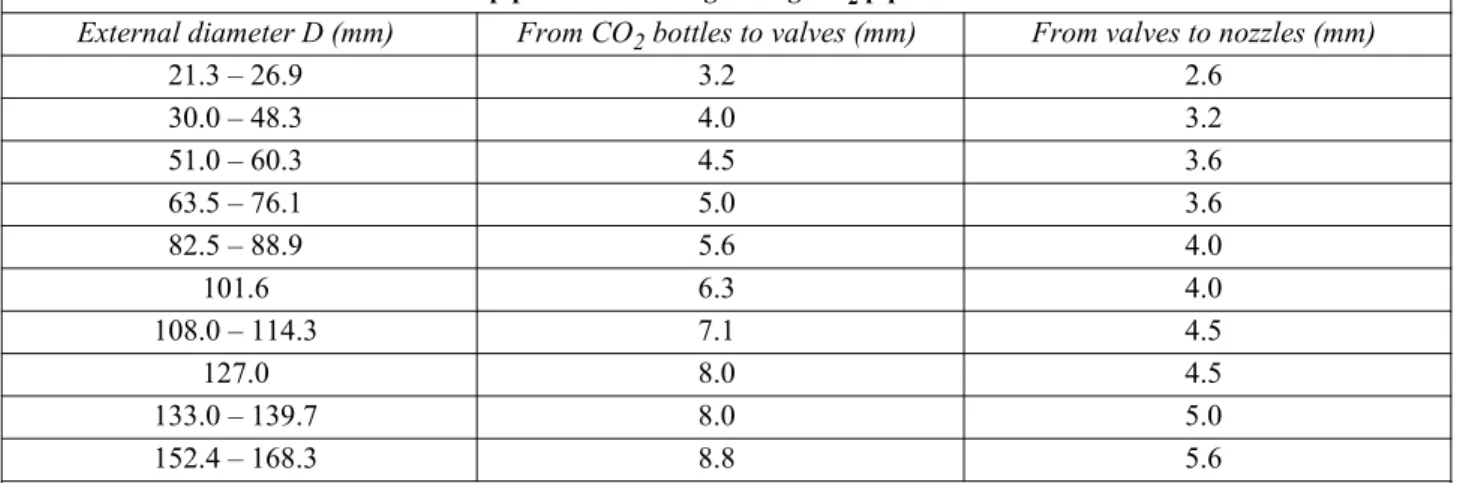
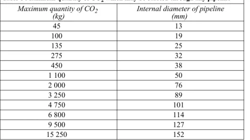
1.3.1.1 The tests and surveys shall be based on MSC.1/Circ.1318 with the below amendments and exemptions. Replacement of flexible hoses for the CO2 system need not follow MSC.1/Circ.1318, but the following minimum requirements shall be applied. Replacement shall:
— follow maker’s recommendation, or
— be done after 10 years if the maker recommendation is not available.
1.3.1.2 CO2 pipes shall be blown through annually to ensure that they are free from debris and not clogged. Test or record of the test shall be presented to the attending surveyor.
1.3.1.3 At biennial (every 24 months) for passenger ships and at each intermediate, periodical or renewal survey for cargo ships, an inspection is to be carried out by an approved service supplier. The record from this inspection is to be filed onboard.
1.3.1.4 High pressure CO2 cylinders are to be subject to periodical hydrostatic testing at maximum intervals of 10 years. Testing is required for not less than 10% of the cylinders every 10 years. If one or more cylinders fail, a total of 50% of the onboard cylinders shall be tested. If further cylinders fail, all cylinders shall be tested.
1.3.1.5 Safety pins preventing release from release station(s) shall be removed according to maker’s instructions. Such safety pins are typically used to securing the CO2 cylinder valves during transportation.
1.3.1.6 The general items for gas systems in 1.2.2 shall also be verified.
1.3.2 Low pressure CO2 systems
1.3.2.1 The test and surveys shall be based on MSC.1/Circ.1318 with the below amendments and exemptions.
1.3.2.2 CO2 pipes shall be blow through annually to ensure that they are free from debris and not clogged. Test or record of the test shall be presented to the attending surveyor.
1.3.2.3 At biennial (every 24 months) for passenger ships and at each intermediate, periodical or renewal survey for cargo ships, an inspection is to be carried out by an approved service supplier. The record from this inspection is to be filed onboard.
1.3.2.4 The annual external inspection of insulated containers is to include spot check of the outer surface beneath the insulation and all connections and equipment fitted to the tank.
1.3.2.5 Low pressure CO2 bulk containers are to be internally surveyed if the content has been released and the container is more than 5 years old. Depending on the result of the survey, hydrostatic testing may be required at the surveyor's discretion.
1.3.2.6 The general items for gas systems in 1.2.2 shall also be verified.
1.3.3 Equivalent gas system
1.3.3.1 Equivalent gas systems are those installed and approved according to MSC/Circ.848 or MSC.1/ Circ.1267. Examples of such systems are:
— Inergen — FM200 — NOVEC 1230.
1.3.3.2 At biennial (every 24 months) for passenger ships and at each intermediate, periodical or renewal survey for cargo ships, an inspection is to be carried out by an approved service supplier. The record from this inspection is to be filed onboard.
1.3.3.3 The gas cylinders are to be subject to periodical hydrostatic testing at maximum intervals of 10 years. Testing is required for not less than 10% of the cylinders every 10 years. If one or more cylinders fail, a total of 50% of the onboard cylinders shall be tested. If further cylinders fail, all cylinders shall be tested.
1.3.3.4 The survey will follow the requirements for CO2 high-pressure systems, adjusted to the applicable pressure. The chemical agents (FM200 and NOVEC 1230) will typically have a design pressure of 25 – 40 bar, whereas the inert gases (Inergen) will typically have a design pressure of 200 – 300 bar on the closed section side and 50-70 bar on the open piping side.
1.3.3.5 System with cylinders installed inside the protected space (MSC/Circ.848, 11 or MSC.1/Circ.1267, 11) shall in addition be check as follows:
— integrity of double release lines inside protected space to be surveyed
— release cabinet to be checked, including alarms on low pressure, as applicable.
1.3.3.6 The general items for gas systems in 1.2.2 shall also be verified.
1.3.4 Halon systems
1.3.4.1 Halon systems are prohibited on ships built after 1994. Some flag state (including all EU and EEA flag states) have required phase out of these systems on all ships flying their flag.
1.3.4.2 Hydrostatic pressure testing of Halon cylinders is no longer required if an external inspection of the cylinders and thickness measurements of lower end confirms that any corrosion and indents are insignificant. The position of the flag administration shall however always be checked for this particular case.
1.3.4.3 At biennial (every 24 months) for passenger ships and at each intermediate, periodical or renewal survey for cargo ships, an inspection is to be carried out by an approved service supplier. The record from this inspection is to be filed onboard.
1.3.4.4 The survey will, except for the testing of cylinders, follow the requirements for equivalent gas system, adjusted to the applicable pressure (typically 30-40 bar for the Halon cylinders). The general items for gas systems in 1.2.2 shall also be verified.
1.3.5 High Expansion foam systems (outside air foam systems)
1.3.5.1 Testing of quality of foam concentrate is to be carried out periodically not later than 3 years after manufacture and annually thereafter. Testing is to be carried out by the manufacturer or an approved service supplier or at a recognised test laboratory.
1.3.5.2 Start of water pumps, foam concentrate pump and fans shall be tested and inspected at the annual survey. It is important that the foam concentrate lines are properly flushed with fresh water after this test. The foam concentrate pump may be tested with water if there are problems with disposal of foam concentrate used in the test.
1.3.5.3 The foam tank shall be checked to confirm that the amount of concentrate is above the minimum required quantity.
1.3.5.4 Distribution pipes for foam solution up to foam generators shall be blow through with air annually and nozzles inspected for debris. Corrective action shall be taken if more than insignificant debris is found. Test or record of the test shall be presented to the attending surveyor.
1.3.5.5 At renewal survey distribution pipes shall be flushed properly with fresh water and inspected to ensure that they are free from debris and not clogged.
1.3.5.6 Distribution ducts for foam shall be inspected for damage.
1.3.5.7 The general items for foam systems in 1.2.3 shall also be verified.
1.3.6 Inside air foam system
1.3.6.1 Inside air foam systems are those installed and approved according to DNV type approval programme for such system or MSC.1/Circ.1271. Examples of trade name for such systems are:
— HotFoam — HiFoam.
1.3.6.2 Testing of quality of foam concentrate is to be carried out periodically not later than 3 years after manufacture and annually thereafter. Testing is to be carried out by the manufacturer or an approved service supplier or at a recognised test laboratory.
1.3.6.3 Start of water pumps and foam concentrate pump shall be tested and inspected at the annual survey. It is important that the foam concentrate lines are properly flushed with fresh water after this test.
1.3.6.4 The foam tank shall be checked to confirm that the amount of concentrate is above the minimum required quantity.
Conditions of generators inside the protected space shall be assessed on a spot checked basis.
1.3.6.5 Distribution pipes shall be blow through with air annually and nozzles inspected for debris. Corrective action shall be taken if more than insignificant debris is found. Test or record of the test shall be presented to the attending surveyor.
1.3.6.6 At renewal survey distribution pipes shall be flushed properly with fresh water and inspected to ensure that they are free from debris and not clogged.
1.3.6.7 The general items for foam systems in 1.2.3 shall also be verified.
1.3.7 Water mist systems
1.3.7.1 Water mist systems are those installed and approved according MSC/Circ’s.668/728 or MSC/Circ.1165.
1.3.7.2 A full flow test is to be carried out each year for one section. Test or record of the test shall be presented to the attending surveyor.
Other tests and inspections as per maker’s recommendation and the Society’s type approval certificate shall be carried out annually.