BCM450
Business Communications Manager
Document Status:StandardDocument Number: NN40160-700
Document Version: 01.01 Date: August 2008
All rights reserved.
The information in this document is subject to change without notice. The statements, configurations, technical data, and recommendations in this document are believed to be accurate and reliable, but are presented without express or implied warranty. Users must take full responsibility for their applications of any products specified in this document. The information in this document is proprietary to Nortel Networks.
Trademarks
Nortel, the Nortel logo, and the Globemark are trademarks of Nortel Networks.
Microsoft, MS, MS-DOS, Windows, and Windows NT are trademarks of Microsoft Corporation. All other trademarks and registered trademarks are the property of their respective owners.
Task List
Introduction . . . 9
Initial Troubleshooting . . . 15
Hardware Troubleshooting . . . 19
To verify the keycodes using Element Manager...24
To verify the keycodes using Telset ...25
To restart the system ...26
Viewing the POST log file ...27
To test the main unit ...29
To troubleshoot the main unit ...29
To test the expansion unit ...29
To troubleshoot the expansion unit ...30
Testing an MBM ...30
Troubleshooting the FEM ...31
To determine why the ATA 2 does not function...31
To determine why there is no dial tone at the ATA2...32
To check the ATA2 wiring...32
To perform a Level 1 reset (configuration reset) ...34
To perform a Level 2 reset (software reset) ...34
Software Troubleshooting . . . 37
To check line programming ...38
To restore data from an archive ...46
To restore the factory configuration ...47
To view the BCM450 software inventory ...48
To obtain updates from the Nortel Technical Support Web page...49
Advanced Troubleshooting . . . 51 Troubleshooting example 1 ...51 Troubleshooting example 2 ...53 Troubleshooting example 3a ...59 Troubleshooting example 3b ...59 Troubleshooting example 4 ...61 Troubleshooting example 5 ...62 Troubleshooting example 6 ...67 Troubleshooting example 7 ...67 Recovery trees . . . 69 Downloading Software . . . 75
To download software from the BCM450 webpage...76
Troubleshooting Tools . . . 79
Accessing the CLI through a serial connection ...81
Understanding system messages . . . 83
To set Release Reasons ...83
Useful Troubleshooting Links . . . 85
To use the Knowledge and Solution Engine...86
Frequently Asked Questions . . . 87
To perform a backup ...87
To restore data from the BCM450 ...88
Completing a warm or cold reset ...89
Recovering a lost password ...89
To view an alarm ...90
To acknowledge an alarm ...91
Using the Element Manager to transfer log files...91
Capturing the current configuration ...93
Viewing the system health ...94
Viewing specific process states ...94
Verify the current software revision ...95
Viewing the system ID and serial number ...95
Contents
Chapter 1 Introduction . . . 9 Purpose . . . 9 Audience . . . 9 Organization . . . 9 Acronyms . . . 10Symbols and conventions used in this guide . . . 12
Related publications . . . 13
Chapter 2 Initial Troubleshooting . . . 15
Navigation . . . 15
Proper installation and routine maintenance . . . 15
Network configuration . . . 15
Site network map . . . 15
Logical connections . . . 16
Device configuration information . . . 16
Other important data about your network . . . 16
Normal behavior on your network . . . 16
Chapter 3 Hardware Troubleshooting . . . 19
Navigation . . . 19
Troubleshooting the BCM450 hardware . . . 19
Check the power source . . . 19
Check LED indicators . . . 19
Check the wiring connections . . . 24
Verify the keycodes . . . 24
Restart or shut down the system . . . 25
Power on self test . . . 27
Testing basic hardware functionality . . . 28
Reset to factory settings . . . 32
Monitoring the boot process . . . 34
Chapter 4 Software Troubleshooting. . . 37
Navigation . . . 37
Verify the software version . . . 37
Check the programming of lines and phones . . . 37
Check line programming . . . 38
Trunk/Line data . . . 38
Properties . . . 40
Preferences . . . 42
Restrictions . . . 45
Assigned DNs . . . 46
Restoring system data . . . 46
Verify the software inventory . . . 48
Viewing the inventory of BCM450 software . . . 48
Obtaining software updates . . . 48
Chapter 5 Advanced Troubleshooting. . . 51
Navigation . . . 51
Example 1: Cannot dial out from an analog trunk . . . 51
Example 2: Cannot dial out from a SIP or H323 VoIP trunk . . . 53
Example 3: IP set is not registering with the BCM450 . . . 58
Example 4: Cannot install keycode or invalid keycode application . . . 60
Example 5: Cannot dial out from digital trunk . . . 61
Example 6: MeetMe Conferencing commands do not work, or conferencing is busy . 66 Example 7: Unable to apply a software update from a USB storage device . . . 67
Example 8: Element Manager incorrectly shows expansion cabinet as empty . . . 68
Chapter 6 Recovery trees . . . 69
Navigation . . . 69
System is not processing calls . . . 69
Start-up profile fails . . . 70
Cannot access BCM450 through Element Manager . . . 71
BCM450 shuts down unexpectedly . . . 73
Chapter 7 Downloading Software . . . 75
Navigation . . . 75
Downloading software from the BCM450 webpage . . . 75
Downloading software from the Nortel web site . . . 77
Chapter 8 Troubleshooting Tools . . . 79
Navigation . . . 79
Service Management . . . 79
Utilities . . . 80
Command Line Interface . . . 80
Accessing the CLI . . . 80
Using the Configuration CLI . . . 81
Using the Maintenance CLI . . . 82
Chapter 9 Understanding system messages . . . 83
Alarms, logs, and traps . . . 83
Reporting for dropped calls . . . 83
Chapter 10 Useful Troubleshooting Links . . . 85
Navigation . . . 85
Partner Bulletins . . . 85
Knowledge and Solution Engine . . . 85
Using the Knowledge and Solution Engine . . . 85
Chapter 11 Frequently Asked Questions . . . 87
Navigation . . . 87
Backup, restore, and reset operations . . . 87
How do I back up the database? . . . 87
How do I restore the BCM450 from a previous backup? . . . 88
How do I complete a Warm Reset or Cold Reset? Is it safe and will I lose customer data? 88 Password protection . . . 89
How do I recover a lost password for the BCM450? . . . 89
Fault management . . . 90
How do I view Alarms? Can I acknowledge and clear them? . . . 90
System and status information . . . 91
How do I capture the logs from the BCM450? . . . 91
How do I capture the current BCM450 configuration? . . . 93
How do I find the BCM450 system health? . . . 94
How do I show specific process states? . . . 94
How do I verify current software revision? . . . 94
How do find the BCM450 System ID and Serial Number? . . . 95
Connectivity problems . . . 95
What is an Ethernet loop, and how do I avoid creating one? . . . 96
IP addresses . . . 96
Can I modify the IP address of the OAM port? . . . 96
Chapter 12
Contacting Technical Support . . . 99
Navigation . . . 99
Gathering critical information . . . 99
Getting Help from the Nortel Web site . . . 100
Getting help over the phone from a Nortel Solutions Center . . . 100
Getting help from a specialist by using an Express Routing Code . . . 101
Chapter 1
Introduction
The Nortel Business Communications Manager 450 (BCM450) provides private network and telephony management capability to small and medium-sized businesses. The BCM450 system integrates voice and data capabilities, and IP Telephony gateway functions into a single telephony system. It also enables you to create and provide telephony applications for use in a business environment.
Purpose
This guide provides procedural information to help you troubleshoot and isolate problems in your BCM450 network.
Audience
The BCM450 Troubleshooting Guide is for use by network administrators responsible for maintaining BCM networks that include BCM450 devices. This guide is also useful for network operations center (NOC) personnel supporting a BCM450 managed services solution. To use this guide, you must:
• be an authorized BCM450 administrator within your organization • know basic Nortel BCM450 terminology
• be knowledgeable about telephony and IP networking technology
Organization
This guide is organized for easy access to information that explains the troubleshooting procedures associated with using the BCM450 system. This guide contains information on the following topics:
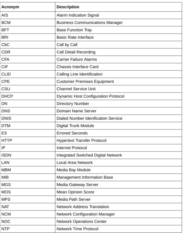
• Initial Troubleshooting on page 15 • Hardware Troubleshooting on page 19 • Software Troubleshooting on page 37 • Advanced Troubleshooting on page 51 • Recovery trees on page 69
• Downloading Software on page 75 • Troubleshooting Tools on page 79
• Understanding system messages on page 83 • Useful Troubleshooting Links on page 85 • Frequently Asked Questions on page 87
• Contacting Technical Support on page 99
Acronyms
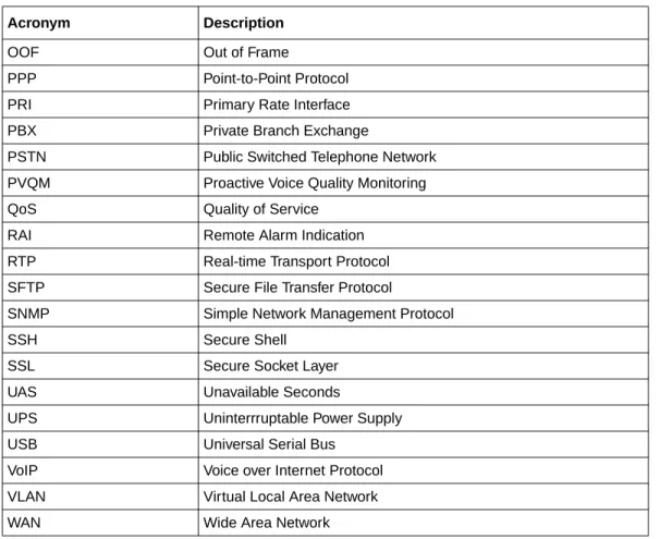
The following is a list of acronyms used in this guide.
Table 1 List of acronyms
Acronym Description
AIS Alarm Indication Signal
BCM Business Communications Manager BFT Base Function Tray
BRI Basic Rate Interface CbC Call by Call
CDR Call Detail Recording CFA Carrier Failure Alarms CIF Chassis Interface Card CLID Calling Line Identification CPE Customer Premises Equipment CSU Channel Service Unit
DHCP Dynamic Host Configuration Protocol DN Directory Number
DNS Domain Name Server
DNIS Dialed Number Idenification Service DTM Digital Trunk Module
ES Errored Seconds
HTTP Hypertext Transfer Protocol IP Internet Protocol
ISDN Integrated Switched Digital Network LAN Local Area Network
MBM Media Bay Module
MIB Management Information Base MGS Media Gateway Server MOS Mean Opinion Score MPS Media Path Server
NAT Network Address Translation NCM Network Configuration Manager NOC Network Operations Center NTP Network Time Protocol
OOF Out of Frame
PPP Point-to-Point Protocol PRI Primary Rate Interface PBX Private Branch Exchange
PSTN Public Switched Telephone Network PVQM Proactive Voice Quality Monitoring QoS Quality of Service
RAI Remote Alarm Indication RTP Real-time Transport Protocol SFTP Secure File Transfer Protocol
SNMP Simple Network Management Protocol SSH Secure Shell
SSL Secure Socket Layer UAS Unavailable Seconds
UPS Uninterrruptable Power Supply USB Universal Serial Bus
VoIP Voice over Internet Protocol VLAN Virtual Local Area Network WAN Wide Area Network
Table 1 List of acronyms
Symbols and conventions used in this guide
These symbols are used to highlight critical information for the BCM450 system:
Caution: Alerts you to conditions where you can damage the equipment.
Danger: Alerts you to conditions where you can get an electrical shock.
Warning: Alerts you to conditions where you can cause the system to fail or work improperly.
Note: A Note alerts you to important information.
Tip: Alerts you to additional information that can help you perform a task.
!
Security note: Indicates a point of system security where a default should be changed, or where the administrator needs to make a decision about the level of security required for the system.
Warning: Alerts you to ground yourself with an antistatic grounding strap before performing the maintenance procedure.
Warning: Alerts you to remove the BCM450 main unit and expansion unit power cords from the ac outlet before performing any maintenance procedure.
Related publications
Related publications are listed below. To locate specific information, you can refer to the
Master Index of BCM450 Library (NN40020-100).
BCM450 Administration and Security Guide (NN40160-601) BCM450 Installation Guide—System (NN40160-301) BCM450 Maintenance Guide (NN40160-503)
Keycode Installation Guide (NN40010-301)
BCM450 Configuration Guide—Devices (NN40160-500) BCM450 Configuration Guide—System (NN40160-501) BCM450 Telset Administration Guide (NN40020-604) CallPilot Telephone Administration Guide (NN40090-500)
CallPilot Contact Center Telephone Administration Guide (NN40040-600) Reporting for Contact Center Troubleshooting
Chapter 2
Initial Troubleshooting
You can better troubleshoot the problems on your network and reduce their impact by preparing for such events in advance. To do this, you must know the following:
• that your system is properly installed and routinely maintained • the configuration of your network
• the normal behavior of your network
Navigation
• Proper installation and routine maintenance on page 15 • Network configuration on page 15
• Normal behavior on your network on page 16
Proper installation and routine maintenance
See the BCM450 Installation Guide—System (NN40160-301) for detailed installation information. This document also outlines the routine tasks required for operating the BCM450.
Network configuration
To keep track of your network’s configuration, gather the information described in the following sections. This information, when kept up-to-date, is extremely helpful when you experience network or device problems.
• Site network map on page 15 • Logical connections on page 16
• Device configuration information on page 16 • Other important data about your network on page 16
Site network map
A site network map identifies where each device is physically located on your site, which helps locate the users and applications that are affected by a problem. You can use the site network map to systematically search each part of your network for problems.
Logical connections
You must know how your devices are connected logically as well as physically. For example, while virtual LANs (VLANs) are not supported on the BCM450 system, VLANs may exist between IP sets connected to the BCM450.
Device configuration information
You should maintain online and paper copies of your device configuration information. Ensure that all online data is stored with your site’s regular data backup. If your site does not have a backup system, copy the information onto a backup disk (such as a CD or zip disk) and store the backup disk at an offsite location.
Other important data about your network
For a complete picture of your network, have the following information available:
• All passwords—Store passwords in a safe place. It is a good practice to keep records of your
previous passwords in case you must restore a device to a previous software version and need to use the old password that was valid for that version.
• Device inventory—It is a good practice to maintain a device inventory, which list all devices
and relevant information for your network. The inventory allows you to easily see the device type, IP address, ports, MAC addresses, and attached devices.
• MAC address-to-port number list—If your hubs or switches are not managed, you must
keep a list of the MAC addresses that correlate to the ports on your hubs and switches.
• Change control—Maintain a change control system for all critical systems. Permanently store
change control records.
• Contact details—It is a good practice to store the details of all support contracts, support
numbers, engineer details, and telephone and fax numbers. Having this information available when troubleshooting can save a lot to time.
Normal behavior on your network
When you are familiar with the performance of your network when it is fully operational, you can be more effective at troubleshooting problems that arise. To understand the normal behavior of your network, monitor your network over a long period of time. During this time you can see a pattern in the traffic flow, such as which devices are typically accessed or when peak usage times occur.
To identify problems, you can use a baseline analysis, which is an important indicator of overall network health. A baseline serves as a useful reference of network traffic during normal operation, which you can then compare to captured network traffic while you troubleshoot network
problems. A baseline analysis speeds the process of isolating network problems. By running tests on a healthy network, you compile normal data for your network. This normal data can then be
used to compare against the results that you get when your network is experiencing trouble. For example, ping each node to discover how long it typically takes to receive a response from devices on your network. Capture and save each device’s response time and when you are troubleshooting you can use these baseline response times to help you troubleshoot.
Chapter 3
Hardware Troubleshooting
Use the tasks in this chapter to troubleshoot problems related to the BCM450 hardware components.
Navigation
• Troubleshooting the BCM450 hardware on page 19 • Power on self test on page 27
• Testing basic hardware functionality on page 28 • Monitoring the boot process on page 34
Troubleshooting the BCM450 hardware
Complete the following tasks, in the order shown below, to troubleshoot some of the common problems that you may encounter with the BCM450 hardware:
• Check the power source on page 19 • Check LED indicators on page 19 • Check the wiring connections on page 24 • Verify the keycodes on page 24
• Restart or shut down the system on page 25
Check the power source
Begin troubleshooting the hardware by checking the power source: • check the connection between the power supply and the main unit • check the connection from the power supply to the electrical outlet
Check LED indicators
After checking the power source, check the LED indicators. This section describes the operation of the BCM450 system LEDs:
• System status LEDs on page 20 • LAN port LEDs on page 21
• Media bay module LEDs (expansion units only) on page 21 • DTM LEDs on page 22
System status LEDs
The chassis of the BCM450 contains two LEDs: a Status LED and a Power LED. The Power LED is located at the bottom left of the chassis; the Status LED is immediately above it. The table
System status LEDs states and descriptions on page 20 describes the meaning of the system status LEDs in the following situations:
• start-up sequence: LED indicators during the normal start-up process • safe-mode start-up sequence: LED indicators during a safe-mode start-up • shutdown sequence: LED indictors during a shutdown or failure
• start-up profile sequence: LED indicators during an initial installation or staging
Table 1 System status LEDs states and descriptions
Power Status
Description Start-up sequence
Solid yellow Solid yellow Power applied to the system.
Solid yellow Off Power on self test (POST); 9 seconds. Solid yellow Solid yellow System initialization; 14 seconds. Solid green Solid yellow Kernel initialization; 8 seconds. Solid green Flashing green Services initialization; 1 minute. Solid green Solid green System running; normal operation. Solid green Solid red Services initialization failure
Safe mode start-up sequence
Solid red Solid green System running with manufacturing settings enabled Solid red Solid red System running in software reset mode
Sold red Flashing yellow System running in configuration reset mode
Shutdown sequence or failure
Solid green Flashing yellow Shutdown in progress Off Solid yellow Shutdown completed
Solid red Flashing yellow Overheating detected; thermal shutdown completed Solid red Solid red Power spike or rail power fluctuation detected
Flashing red Solid red Rail power fluctuation; power monitor shutdown completed Solid yellow Solid red Power spike shutdown completed
Off Off No power; system is shut down
Start-up profile sequence
Flashing yellow Flashing yellow Start-up profile executing
Flashing green Flashing green Start-up profile completed (USB device can be removed) Solid green Solid green Start-up profile successfully applied
LAN port LEDs
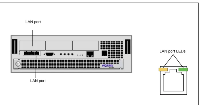
Each LAN port on the main unit and expansion unit has two LEDs. These LEDs indicate the status of the connection for that LAN port. The figure LAN port LED locations on page 21 shows the location of these LEDs on the main unit.
Figure 1 LAN port LED locations
The table LAN port and expansion port LED indicators on page 21 describes the possible LED states for the LAN ports LEDs.
Media bay module LEDs (expansion units only)
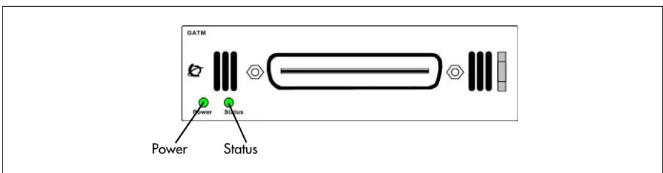
The two media bay module (MBM) LEDs on an expansion unit show the power and status of the MBM. The figure MBM LEDs on page 22 shows the location of the (Power) and (Status)
LEDs on an MBM. The power and status LEDs are in the same location on all MBMs. Table 2 LAN port and expansion port LED indicators
LED Status Description
Yellow (left LED) On
The LAN port is operating at 10 Mb/s. Green (right
LED) On
The LAN port is operating at 100 Mb/s. Both LEDs Off No connection.
Any LED Flashing The LAN port is sending or receiving network data. The frequency of the flashes increases with increased traffic.
LAN port
LAN port LEDs
Figure 2 MBM LEDs
The table MBM LED descriptions on page 22 describes the possible MBM LED states.
DTM LEDs
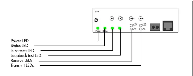
The DTM has additional LEDs that are not on most other MBMs. The figure DTM LEDs on page 23 shows the location of the DTM LEDs.
Table 3 MBM LED descriptions Power Status Description
Off Off The MBM has no power, or a failure occurred on the MBM power converter. On Off BCM450 to expansion unit failure or system initialization.
On Blinking Hardware is working, but an operational problem exists such as: • no link to the main unit is detected
• frame alignment is lost on messages from the main unit • bandwidth not allocated
• MBM is in maintenance state
• MBM is in download state (GASM, GATM4/GATM8) Blinking Blinking The MBM has power, but a hardware problem exists such as:
• partial failure of power converter • thermal overload
• fan failure
On On The MBM is ready to operate.
Figure 3 DTM LEDs
The table DTM LED functions on page 23 describes the functions of the DTM LEDs.
Table 4 DTM LED functions
LED Status Descriptions
Power – See “Media bay module LEDs (expansion units only)” for details. Status – See “Media bay module LEDs (expansion units only)” for details.
In service Flashing The T1, ETSI, or PRI trunks are out of service because a loopback test is running or the DTM is initializing.
Loopback test On A continuity loopback test is running.
Receive alarm On A problem with the received digital transmission. This half-duplex link does not work.
Receive error On A small error as a result of degraded digital transmission. Possible causes are an ohmic connection, water ingress, or too long a loop.
Transmit alarm On The DTM cannot transmit. The DTM sends an alarm indication signal (AIS) to the terminating switch. This half-duplex link does not work.
Transmit error On The DTM is sending a remote alarm indication (RAI) carrier failure alarm (CFA) to the terminating switch. If the transmit alarm is not on, this error indicates a far-end or cable problem.
All LEDS Flashing The DTM is initializing.
Power LED Status LED In service LED Loopback test LED Receive LEDs Transmit LEDs
BRIM LEDs
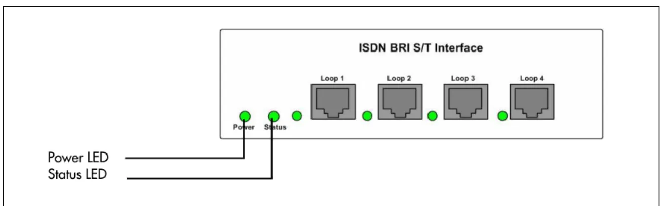
The BRIM has one additional LED beside each RJ-48C jack. These LEDs are on when the ISDN line is active. The figure BRIM LEDs on page 24 shows the location of the LEDs on a BRIM.
Figure 4 BRIM LEDs
For more information on the power and status LED functions, see Media bay module LEDs (expansion units only) on page 21.
Check the wiring connections
After you check the power source and the LEDs, begin to check the wiring. Check the connections between the following components:
• the expansion unit and the main unit
• the main unit and to the MBMs—make sure that the cables are properly seated and are connected to the correct ports
• the power supply and the AC power outlet
• if you are using a UPS, check the connection from:
— the USB port on the BCM450 to the USB port on the UPC — the UPS and the electrical outlet
— the connection from the power supply to both the UPS and the BCM450 main unit
• the lines and extensions connected through the RJ-21 telephony connector
• the auxiliary equipment—connections at the auxiliary terminal block, or at the patch panel
Verify the keycodes
If a specific feature is not functioning, verify that the feature is included in your installed keycodes. This section provides procedure for verifying the installed keycodes using either Element Manager or Telset. For more detailed information about retrieving and entering the keycode for your system, see the Keycode Installation Guide (NN40010-301).
To verify the keycodes using Element Manager
1 In the Task Navigation Panel, select the Configuration tab.Power LED Status LED
2 Select the System folder and click the Keycodes task.
The Keycodes panel displays and the installed features appear in the Keycodes list. 3 To enter a new keycode, click Load File.
4 Browse to where you saved the keycode file you downloaded from KRS. 5 Click Open.
The file uploads and the feature appears in the Keycodes list.
To verify the keycodes using Telset
1 Select Feature 9*8 from a two-line display telephone. 2 Enter the following user ID and password:User ID: SETNNA Password: CONFIG
The numerical values of the user ID and password are 738662 and 266344, respectively. 3 Press NEXT to scroll through the menu and select Feature Codes.
4 Press OK.
The system ID (SID) displays. 5 Press NEXT.
6 Enter your sequence ID.
7 Press NEXT to scroll through the list and perform one or both of the following tasks: a To activate features, select Feature List.
• Press SHOW to view the available features.
• Use the soft keys to activate features for your system. b To enter a new keycode, select Entitlement Code. • Press SHOW to view the current keycode.
• Use the soft keys to modify the keycode for your system.
Restart or shut down the system
You can use the Reset utility in Element Manager to: • reboot the BCM450 system
• perform a warm reset of telephony services • perform a cold reset of telephony services • shut down the system
To restart the system
Use this procedure to restart the system from the Element Manager. 1 Select Administration > Utilities > Reset.
2 Click the appropriate reset button. Table 5 lists the Reset functions.
Table 5 Reset functions
Function Description Impact
Reboot BCM450 System Restarts the operating system of the BCM450 system
Temporarily stops all services on the system. Restarts all services. This operation does not affect configuration parameters or programming.
Warm Reset Telephony Services
Restarts telephony services running on the BCM450 system
Restarts all telephony services, including LAN CTE, Voicemail, and IP telephony.
This operation does not affect configuration parameters or programming.
Cold Reset Telephony Services
Resets telephony programming of the BCM450 system to the factory defaults for that software level
Affects all telephony services, including LAN CTE, Voicemail, and IP telephony.
Telephony services restart with all telephony programming at default values for the specified region, template, and start DN, for the current software release level. A cold reset erases voice message mailboxes and messages if the DN length is not set to system defaults. For information about setting the DN length, refer to the BCM450 Device
Configuration Guide.
Shutdown BCM System Shuts down the BCM450. Stops all services running on the system.
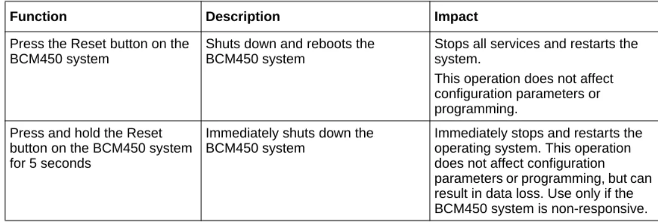
To restart the system from the BCM450 hardware, use the reset button as described in Hardware reset functions on page 27.
Note: When you restart the BCM450 system using the Reset button, the system will wait for 10 seconds for a user to log into the Maintenance CLI. If a user does not log in during that time period, the BCM450 will reboot to the Main OS.
Power on self test
The power on self test (POST) feature tests basic hardware functionality when the BCM450 system powers up, and stores the results in a log file. You can view the log file for hardware failures.
Viewing the POST log file
1 Use Element Manager to transfer the log files to your PC. Refer to the “BCM450 Log
management” chapter in the BCM450 Administration and Security Guide (NN40160-601) for information about how to transfer log files.
2 View the bootloader.log file.
3 Check the log file for errors. Figure 5 on page 28 shows a bootloader.log file with no errors;
Figure 6 on page 28 shows a file with errors.
Table 6 Hardware reset functions
Function Description Impact
Press the Reset button on the BCM450 system
Shuts down and reboots the BCM450 system
Stops all services and restarts the system.
This operation does not affect configuration parameters or programming.
Press and hold the Reset button on the BCM450 system for 5 seconds
Immediately shuts down the BCM450 system
Immediately stops and restarts the operating system. This operation does not affect configuration parameters or programming, but can result in data loss. Use only if the BCM450 system is non-responsive.
Figure 5 Example: Bootloader.log file with no errors
Figure 6 Example: Boot file with errors
Testing basic hardware functionality
This section describes how to test the components of the BCM450 system, and how to troubleshoot them if they fail the test.
Use the following procedures to help isolate and identify problems with your BCM450 hardware: • To test the main unit on page 29
• To troubleshoot the main unit on page 29 • To test the expansion unit on page 29
• To troubleshoot the expansion unit on page 30 • Testing an MBM on page 30
• Troubleshooting the FEM on page 31
• To determine why the ATA 2 does not function on page 31 • To determine why there is no dial tone at the ATA2 on page 32 • To check the ATA2 wiring on page 32
• Reset to factory settings on page 32
To test the main unit
If you have the digital station feature included in your installed keycode, use the following test to ensure the main unit is operating properly:
1 Go to an extension that is connected to the RJ-21 telephony connector on the main unit. 2 Check for a dial tone.
3 Use this extension to make a call to another extension on the system.
4 If this system has an expansion unit with a media bay module (MBM) that supports extensions, repeat steps 3 and 4 for an extension connected to the expansion unit. 5 Go to an extension that has access to one of the lines on the main unit.
6 Select the line or line pool to which the line belongs. 7 Check for a dial tone.
8 Make a call using the line or line pool.
9 If this system has an expansion unit with an MBM that supports lines, repeat steps 6 to 8 with an extension that can access one of the lines connected to the expansion unit.
To troubleshoot the main unit
If a test fails, use the following procedure:1 Verify that any nonfunctional feature is included in your installed keycode.
2 Check the wiring to the main unit and to the MBMs. Make sure that the cables are properly seated and are connected to the correct ports.
3 Reboot the BCM450 system. 4 Check LEDs.
5 Use Element Manager or the Telset Administration feature to check the programming for the lines or extensions that failed the call test.
6 If the programming is incorrect, use the Backup and Restore Utility to load a recent backup of system programming. If a recent backup is not available, correct the programming using Element Manager or the Telephone Administration feature.
To test the expansion unit
Use the following test to ensure the expansion unit is operating properly: 1 Make sure that the BCM450 system is fully booted.
2 Check the power and status LEDs on the MBM that is inserted in the expansion unit. Both LEDs must be solid green. If either LED is not solid green, a problem exists with the MBM or the expansion unit.
3 If the expansion unit has an MBM that supports extensions, go to an extension that is connected to the MBM.
4 Check for a dial tone.
5 Use this extension to make a call to another extension on the system.
6 If the expansion unit has an MBM that supports lines, go to an extension that has access to one of the lines on the MBM.
7 Select the line or line pool to which the line belongs. 8 Check for a dial tone.
9 Make a call using the line or line pool.
To troubleshoot the expansion unit
1 Check that the correct feature for the expansion unit is included in your installed keycode. 2 Check that the expansion port is connected to the proper connector.
3 Check the wiring to the MBM. Make sure that the cables are properly seated and are connected to the correct ports with proper LED indications.
4 Check that the switches on the MBM are all set to on.
If the MBM is a GASM or GATM, all the switches on the right are not on.
To check the MBM switches, you must remove the MBM from the expansion unit.
5 Perform a firmware download to ensure that the correct version is loaded on the ASM/GASM or GATM unit.
6 Use Element Manager or Telset Admin to check the programming for the lines or extensions connected to the MBM.
7 Reboot the system to ensure that the BCM450 main unit functions correctly.
8 If the programming is incorrect, use the Backup and Restore Utility to load a recent backup of system programming. If a recent backup is not available, correct the programming using Element Manager or the Telephone Administration feature.
Testing an MBM
Use the following procedure to test an MBM installed in the main unit or expansion cabinet.
If you are experiencing an issue with an FEM, ensure all DIP switches are set to the On position.
Procedure steps
Step Action
1 Check the Power and Status LEDs on the MBM. Both LEDs must be solid green. If either LED is not solid green, a problem exists with the MBM. 2 Go to an extension on the MBM if it is a station MBM.
Go to an extension that has access to one of the lines on the MBM if it is a trunk MBM. Select the line or line pool to which the line belongs.
3 Check for a dial tone.
4 Use this extension to make a call to another extension on the system if it is a station MBM.
OR
Make a call using the line or line pool if it is a trunk MBM.
5 Use this extension to make a call to an external telephone number if you are testing a station MBM.
--End--Determining why an MBM does not appear in Element Manager
Use the following procedure if an installed MBM does not appear in Element Manager.
Procedure steps
Step Action
1 Check that the correct feature is inclueded in your installed keycode. 2 Check that both the Power and Status LEDs on the MBM are solid green. 3 If the Power LED is off, and the MBM is installed in the expansion cabinet,
check that the power supply cable is properly seated in the expansion cabinet and the power supply is connected to a working power outlet.
4 Ensure that the MBM is properly seated in the MBM bay.
5 If the Status LED is not solid green, and the MBM is installed in the expansion cabinet, check that the Expansion cable is properly seated in the Expansion port on the expansion cabinet and on the main unit.
6 Ensure that the MBM is enabled using either Element Manager or Telset Administration. If the MBM is enabled, disable and re-enable it.
7 Ensure that all DIP switches are set correctly.
--End--Troubleshooting the FEM
Use the following procedure to troubleshoot an installed fibre expansion module (FEM). 1 Ensure that all six connector LEDs are lit.
2 If all six LEDs are not lit, ensure that all six DIP switches are set to the On (up) position.
--End--To determine why the ATA 2 does not function
1 Check for a dial tone using an analog device.3 Check that the correct feature for digital sets is included in your installed keycode. 4 Verify that the ATA2 is connected to a digital station port.
5 Allow sufficient startup time (30–60 sec).
6 Plug an analog device into the phone port of the ATA2 and check for a dial-tone. 7 In Element Manager, verify that the ATA 2 is correctly configured:
a Select Configuration > Telephony > Sets > All DNs.
b Select the appropriate DN from the list and click the ATA settings tab. The options for the Device Type are Modem or Telephone.
To determine why there is no dial tone at the ATA2
1 If you hear no dial tone, replace a single-line telephone for the data communication device. 2 If you hear no dial tone at the ATA2 unit:
a Disconnect the line side of the ATA2. Connect a digital telephone to the ATA2 port. b Check that the connection from the ATA2 to the BCM450 hardware works correctly.
To check the ATA2 wiring
1 Use an analog phone to test the ATA2. 2 Check the following connections:a ATA 2 to the terminal
The resistance must be 200 ohms or less for data applications and 1300 ohms or less for voice applications.
b BCM450 hardware to the ATA2
The wiring must be equivalent to 800 m of 0.5 mm wire (2600 ft. of 24-AWG) or less. Do not use bridge taps and loading coils between the BCM450 hardware and ATA2.
Reset to factory settings
This section describes how to reset the BCM450 system to the factory settings or a stable working condition using the reset switch (see the figure Reset switch location on page 33). When the BCM450 is in this condition, you can make further modifications.
Figure 7 Reset switch location
Some possible situations in which you use the reset feature are:
• If the BCM450 system is configured incorrectly to an extent that it is no longer functional. The customer must use a level 1 reset to return to the default system programming and restore a previous configuration or reconfigure the system.
• If distributors want to reuse BCM450 systems, they must first erase all customer-specific data using a level 1 or level 2 reset.
Reset levels
Reset to factory settings is a stand-alone feature that has the following levels of reset:
• Level 1 reset erases all customer-specific data and restores the default configuration for all
components. This reset leaves the software components untouched. That is, the system has the latest release and patch level of the software installed. Only the system and user configuration data is erased and replaced with default values.
• Level 2 reset erases all customer and system configuration data and all software releases and
patches. This reset re-installs the original factory configuration settings.
Warning: If you perform a Level 2 reset to solve an undetermined problem and still have access to Element Manager, you must retrieve all the log files for technical support before performing the Level 2 reset. A Level 2 reset erases all log files from the system.
Activate the reset feature
You activate the reset feature through the Maintenance CLI or the Configuration CLI. When you initiate a reset from the CLI menu, no further action is needed to complete the reset. You can monitor the progress of the reset by observing the LED states, or through the serial connection.It is important that you wait for the system to complete the reset before taking any further action; do not interrupt the reset process.
To perform a Level 1 reset (configuration reset)
1 Access the CLI. For information about how to access the CLI, refer to Command Line Interface on page 80.
2 From the Configuration CLI, select option 4—Configuration Reset. If you are using the Maintenance CLI ,select option 5—Configuration Reset.
3 The LEDs will progress through the start-up and shut down sequence. This process may take more than 2 minutes.
4 A Staus LED that is flashing yellow, and a Power LED that is solid red, indicates that a configuration reset is in progress. This process may take more than 2 minutes.
5 The system reboots to the Main OS. This process may take more than 2 minutes.
To perform a Level 2 reset (software reset)
1 Access the CLI. For information about how to access the CLI, refer to Command Line Interface on page 80.
2 From the Configuration CLI, select option 5—Software Reset. If you are using the Maintenance CLI ,select option 6—Software Reset.
3 The LEDs will progress through the start-up and shut down sequence. This process may take more than 2 minutes.
4 A Staus LED that is flashing yellow, and a Power LED that is solid red, indicates that a software reset is in progress. This process may take more than 5 minutes.
5 The system reboots to the Main OS. This process may take more than 2 minutes.
Monitoring the boot process
1 Connect a serial cable with a 9-pin female connector from the serial port on a PC to the serial port on the BCM450.
2 Ensure that you use the following settings: • bits per second: 115200
Warning: Before performing a Level 1 or Level 2 reset, review all the effects of the levels of reset. See Reset levels on page 33.
• data bits: 8 • parity: N • stop bits: 1 • no flow control
3 Use a terminal emulation program, such as Hyperterminal or Nortel CLI Manager, to establish a connection to the BCM450.
4 Reboot the system and observe the boot process. Figure 8 shows an example of a boot process when there is failed or missing memory; Figure 9 shows an example of a boot process when there is a failed or missing hard drive.
Figure 8 Boot process with failed or missing memory
Chapter 4
Software Troubleshooting
Use the information in this chapter to troubleshoot problems related to the BCM450 software components.
Navigation
Complete the following tasks, in the order shown below, to troubleshoot some of the common problems that you may encounter with the BCM450 software:
• Verify the software version on page 37 • Verify the keycodes on page 37
• Check the programming of lines and phones on page 37 • Restoring system data on page 46
• Verify the software inventory on page 48
Verify the software version
In the Element Manager, select Help > About. A panel displays and provides information about the Element Manager, such as the Release level.
Verify the keycodes
If a specific feature is not functioning, verify that the feature is included in your installed
keycodes. For information about how to verify the installed keycodes, see Verify the keycodes on page 24.
Check the programming of lines and phones
You can use the Element Manager to view the programming of lines and phones. When you view the lines, the information on the panels may vary, depending on the type of line.
The Element Manager displays line information in two sections:
• The main section, Trunk/Line data, is located at the top of the screen and provides a table of lines and the current or default settings.
• The bottom section contains three tabs. The contents of the tabs may vary, depending on the line selected in the top table.
— The Properties tabbed panel provides the settings for individual line characteristics. — The Preferences tab shows information that may vary from trunk to trunk
— The Restrictions tabbed panel allows you to define which restrictions will be active for individual lines. Note that lines that are assigned to the same line pool will automatically assign the same restrictions.
— The Assigned DNs tabbed panel provides a quick way to assign lines to telephones. You must use the DN records panels to assign line pools to telephones.
Check line programming
Use the following procedure to check line programming in your BCM450 system.
To check line programming
1 In the Task Navigation Panel, select the Configuration tab. 2 Select Telephony > Lines.
3 Verify that the programming for all lines is correct; see Trunk/Line data on page 38 for an explanation of the fields on the panel.
4 Select a line, and then select a tab:
a Select the Properties tab and verify that the settings are correct; see Properties on page 40 for an explanation of the fields on the tab.
b Select the Preferences tab and verify that the settings are correct; see Preferences on page 42 for an explanation of the fields on the tab.
c Select the Restrictions tab and verify that the settings are correct; see Restrictions on page 45 for an explanation of the fields on the tab.
d Select the Assigned DNs tab and verify that the settings are correct; see Assigned DNs on page 46 for an explanation of the fields on the tab.
5 Repeat step 4 for the remaining lines.
6 Correct any programming problems, or restore the system data; see “Restoring system data” on page 46 for more information.
Trunk/Line data
The top-level Table View panel shows line records for all lines active on the system, and the common assigned parameters.
Table 7 on page 38 describes the fields found on the Trunk/Line Data main panel.
Table 7 Trunk/Line Data main panel (Sheet 1 of 3)
Attribute Value Description
Line This list contains all the possible line numbers for the system, including target lines.
Configure only those lines that are active on the system. (Click the Active check box and ensure that the Inactive check box is empty).
Trunk Type PSTN-based lines, VoIP, Target
There are three main categories of lines: PSTN-based lines: (analog, T1, PRI, BRI)
Voice over IP (VoIP) trunks, which connect through the LAN or WAN.
Target lines, which are internal channels that provide direct dial capability.
Name <maximum of seven alphanumeric characters>
Identify the line in a way that is meaningful to your system, such as by the type of line and line pool or the DN it is attached to in the case of target lines.
Control Set DN <control telephone DN> Default: 221 (default Start DN)
Enter a telephone DN for a telephone that you want to use to turn service off or on for other telephones using this line. The control telephone must have the line assigned, or must be assigned to the line pool the line is in.
Tips: External lines and telephones must be programmed to use one of the Scheduled Services: Ringing, Restriction, and Routing Services.
For maximum flexibility, Nortel recommends that you create two different control telephones, one for the lines and one for the telephones.
You can turn on a service manually or automatically for all external lines from an assigned control telephone. However, you cannot combine schedules. A service can only be active as normal service or one of the six schedules at any one time. Several schedules can be active at one time, but they must use different services.
Line Type Public
Private to: <telephone DN> Pool A to O,
BlocA to BlocF
Define how the line is used in relation to other lines in the system.
• Public line: can be accessed by more than one telephone.
• Private line: can be assigned only to one telephone and the prime telephone for that line. Enter the internal number of the telephone.
• Pool A - O (analog and T1 lines) BlocA to BlocF (PRI and VoIP lines): assigns the line to one of the line pools. If a line is assigned to a line pool, but is not assigned to any telephone, that line is available only for outgoing calls.
Bloc line pools must be used in conjunction with routes and destination codes. Target lines cannot be put into line pools.
Prime set DN: <telephone DN> None
Assign a telephone to provide backup answering for calls on the line. For an Auto Answer line, calls are redirected if the received number is invalid or the target line is busy, and if the
If busy parameter is set To prime.
Each line can be assigned only one prime telephone. Table 7 Trunk/Line Data main panel (Sheet 2 of 3)
Properties
The Properties tab shows basic line properties. Not all fields apply to all types of lines. The Properties tab is shown in Figure 10 on page 41.
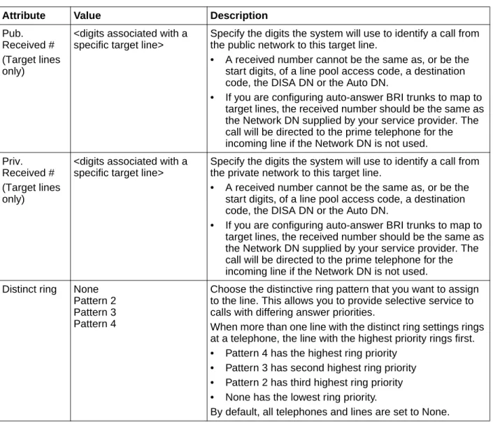
Pub. Received # (Target lines only)
<digits associated with a specific target line>
Specify the digits the system will use to identify a call from the public network to this target line.
• A received number cannot be the same as, or be the start digits, of a line pool access code, a destination code, the DISA DN or the Auto DN.
• If you are configuring auto-answer BRI trunks to map to target lines, the received number should be the same as the Network DN supplied by your service provider. The call will be directed to the prime telephone for the incoming line if the Network DN is not used. Priv.
Received # (Target lines only)
<digits associated with a specific target line>
Specify the digits the system will use to identify a call from the private network to this target line.
• A received number cannot be the same as, or be the start digits, of a line pool access code, a destination code, the DISA DN or the Auto DN.
• If you are configuring auto-answer BRI trunks to map to target lines, the received number should be the same as the Network DN supplied by your service provider. The call will be directed to the prime telephone for the incoming line if the Network DN is not used. Distinct ring None
Pattern 2 Pattern 3 Pattern 4
Choose the distinctive ring pattern that you want to assign to the line. This allows you to provide selective service to calls with differing answer priorities.
When more than one line with the distinct ring settings rings at a telephone, the line with the highest priority rings first. • Pattern 4 has the highest ring priority
• Pattern 3 has second highest ring priority • Pattern 2 has third highest ring priority • None has the lowest ring priority.
By default, all telephones and lines are set to None. Table 7 Trunk/Line Data main panel (Sheet 3 of 3)
Figure 10 Properties details panel
Table 8 on page 41 defines the fields on this panel and indicates the lines.
Table 8 Properties line settings (Sheet 1 of 2)
Attribute Value Description
Legend: Loop = analog/digital loop; GS = ground start; DID = DID; E&M = E&M; BRI = BRI; DPNSS = DPNSS; VoIP = VoIP; TL = Target. Note: PRI fields are all included under the main table.
Trunk mode Loop
Unspr Supervised *Earth calling *Loop guarded *Loop unguarded **ROE, ROI
Define whether disconnect supervision, also referred to as loop supervision, releases an external line when an open switch interval (OSI) is detected during a call on that line. You must set this to Supervised if a loop trunk has its Answer mode set to Auto or if you enable Answer with DISA. Disconnect
supervision is also required to conference two external callers. The line must be equipped with disconnect supervision from the central office for the Supervised option to work.
* These listing only appear for UK analog lines. ** These appear only for Australia.
Dial mode Loop GS DID E&M
Pulse Tone
Specify whether the system uses dual tone multifrequency (DTMF) or pulse signaling on the trunk.
Tone does not appear if Signaling is set to Immediate (T1 DID &T1 E&M trunk types only).
Loss package Loop (analog only) Short CO Medium CO Long CO Short PBX Long PBX
Select the appropriate loss/gain and impedance settings for each line.
Impedance (Ohms) Loop (analog only)
Preferences
The Preferences tab shows information that may vary from trunk to trunk. Most of this information needs to coordinate with the line service provider equipment.
The Preferences tab is shown in Figure 11.
Figure 11 Preferences details panel
Signaling DID E&M
WinkStart Immediate DelayDial
Select the signal type for the line. The immediate setting does not appear for T1 E&M or T1 DID trunks connected to a DTM if the Dial mode is set to tone.
Make sure that this matches the signal type programmed for the trunk at the other switch.
Link at CO Loop (analog only)
<check box> Some exchanges respond to a Link signal, also called hook flash (FEATURE 71), by providing an alternative line for making outgoing calls.
Enabling Link at CO causes the system to apply the restrictions on outgoing calls to the digits dialed after the Link signal. As well, the call on the alternative line is subject to all restrictions. Disabling Link at CO prevents a Link signal from resetting the BCM450 restrictions in cases where the host exchange does not provide an alternative line.
Line Tuning Digit drop-down menu Select the line tuning digit to use. When a trunk is connected, the BCM450 starts a call and sends this digit to the CO to turn off the dial tone signal, and then tests the line to optimize the trunk levels. The default digit is 1. You may need to change the default digit if your CO uses the digit 1 to route the call to a special service or to a second dial tone or busy/re-order tone. Select the digit that will result in silence on the trunk.
Table 8 Properties line settings (Sheet 2 of 2)
Attribute Value Description
Legend: Loop = analog/digital loop; GS = ground start; DID = DID; E&M = E&M; BRI = BRI; DPNSS = DPNSS; VoIP = VoIP; TL = Target. Note: PRI fields are all included under the main table.
Table 9 defines the fields on this panel and indicates the lines.
Table 9 Preferences details fields for lines (Sheet 1 of 3)
Attribute Value Description
Legend: Loop = analog/digital loop; GS = ground start; DID = DID; E&M = E&M; BRI = BRI; DPNSS = DPNSS; VoIP = VoIP; TL = Target and DASS2. Note: PRI fields are all included under the main panel.
Auto privacy Loop GS DID E&M BRI VoIP
<check box> Define whether one BCM450 user can select a line in use at another telephone to join an existing call.
Full autohold Loop BRI DPNSS VoIP
<check box> Enables or disables Full autohold.
When enabled, if a caller selects an idle line but does not dial any digits, that line is automatically placed on hold if you then select another line.
Full autohold is always in place for T1 E&M trunks because it has no meaning for incoming-only T1 DID trunks.
The default setting should be changed only if Full autohold is required for a specific application.
Aux. ringer Loop GS DID E&M BRI DPNSS VoIP TL
<check box> Turn the auxiliary ringer on or off for all telephones using this line.
When programmed on a line, the auxiliary ringer will ring every time a call is received.
Note: When programmed only on a telephone, no ring occurs for a transferred call. An auxiliary ringer can also be programmed in Services to ring for a line placed into a scheduled Ringing service.
ANI Number DID E&M
<check box> Define whether the telephone number of the caller will be shown for this line.
For T1 E&M and T1 DID trunks connected to a DTM, this setting only appears if Signaling is set to WinkStart.
The central office must deliver ANI/DNIS in DTMF mode. No additional equipment is required.
DNIS Number E&M
<check box> Defines whether the digits dialed by an external caller on this line will be shown.For T1 E&M trunks connected to a DTM, this setting only appears if Signaling is set to WinkStart and Answer mode is set to Manual.
Distinct Rings in use
<read-only> Indicates if a special ring has been assigned. See Distinct Ring on the main table.
Answer mode Loop GS E&M BRI DPNSS Manual
Auto
Define whether a trunk is manual or automatic answer.
Auto answer mode allows the trunk to be a shared resource by the system telephones. This shared resource is created through routing to target lines or using DISA.
For auto answer trunks being used to allow remote call-in from system users, the trunk can be configured to answer with a straight dial tone, if DISA has not been enabled. It can also be configured to answer with a stuttered dial tone if DISA is enabled and the caller is expected to enter a CoS password. The CoS password defines which system features the caller is permitted to access.
Manual answer trunks are assigned to one or more telephones. The assigned telephones exclusively own the line.
Note: You require Disconnect supervision on the line if loop start trunks are to operate in auto-answer mode.
Answer with DISA Loop GS E&M BRI
<check box> Define whether the system prompts a caller for a six-digit class of service (CoS) password. This setting appears for T1 loop start, T1 E&M lines that have auto-answer mode, and analog trunks. Set this option to No for T1 E&M lines on a private network that have auto-answer mode.
If busy TL
To Prime Busy Tone
Define whether a caller receives a busy tone or the call forwards to the prime telephone when the target line is busy. Busy tone only works for PRI trunks.
Tips: The duration of an open switch interval (OSI) before BCM450 disconnects a call is programmed by the Disconnect timer setting.
Voice Message Center
Loop GS DID E&M BRI DPNSS VoIP TL
Center 1 - Center 5
If this line connects t o a remote voice mail, either through the private network or at the Central Office, indicate which Center number has been configured with the contact number.The system calls that number to check voice mail messages when a message indicator is presented to a telephone.
Redirect to Loop GS DID E&M TL
<dial string> Enter a dial string (including destination code) to redirect the line to an external telephone, such as a call attendant on another system.
If you want to stop redirection, you need to delete the dial string and allow the record to update.
Warning: If the dialstring is set up, the line will immediately be redirected out of the system not ringing any telephone.
Table 9 Preferences details fields for lines (Sheet 2 of 3)
Attribute Value Description
Legend: Loop = analog/digital loop; GS = ground start; DID = DID; E&M = E&M; BRI = BRI; DPNSS = DPNSS; VoIP = VoIP; TL = Target and DASS2. Note: PRI fields are all included under the main panel.
Restrictions
Assigning Line restrictions and Remote Access Package restrictions are part of the configuration for controlling calls out of the system (line restrictions) and into the system from a private network node or from a remote user calling in over the PSTN lines (Remote Access Packages).
The Restrictions tab shows the restrictions for a line.
Table 10 describes the fields on this panel.
Warning: Enable modules
If you disabled any trunk media bay modules prior to performing programming, enable them now to ensure your system will function properly.
Table 10 Restrictions
Attribute Values Description
Use remote package <remote package #> If the line is being used to receive external calls or calls from other nodes on the private network, ensure that you indicate a remote package that provides only the availability that you want external callers to have. This attribute is typically used for tandeming calls.
Schedule Default: Normal, Night, Evening, Lunch, Sched 4, Sched 5, Sched 6 Line Restrictions -
Use Filter
<00-99> Enter the restriction filter number that applies to each schedule.
(controls outgoing calls) Remote Restrictions
- Use Filter
<00-99> Enter the restriction filter that applies to each schedule. This setting provides call controls for incoming calls over a private network or from remote user dialing in over PSTN)
Table 9 Preferences details fields for lines (Sheet 3 of 3)
Attribute Value Description
Legend: Loop = analog/digital loop; GS = ground start; DID = DID; E&M = E&M; BRI = BRI; DPNSS = DPNSS; VoIP = VoIP; TL = Target and DASS2. Note: PRI fields are all included under the main panel.
Assigned DNs
The Assigned DNs tabbed panel displays the DN properties for lines that are assigned to telephones.
This information can also be configured on the DN record. Any information added, deleted or modified in this table reflects in the DN record.
Restoring system data
If the programming of lines and extensions is incorrect, you can restore from an archive file, or you can restore the system to factory defaults. This section provides the procedures to follow to restore system data from an archive file, and to restore factory defaults. For information about the effects of performing a restore operation, or about optional components, see the BCM450
Administration and Security Guide (NN40160-601)
Restoring data from an archive
To restore data from an archive
1 In the task panel, click the Administration tab.2 Open the Backup and Restore folder, and then click Restore.
The Restore panel opens. The Restore From selection field has BCM as a default value. 3 In the Restore From selection field, select the location of the archive file to restore:
• BCM
• My Computer • Network folder • FTP server • SFTP server • USB storage device • Factory Default 4 Click the Restore button.
The Select Components to Restore window opens.
Note: Lines that do not allow single-line assignment, such as PRI lines and VoIP lines, will not display this tabbed panel.
Caution: A backup operation can interrupt services running on the BCM450. A warning displays whenever the backup will cause a service interruption. If you want to perform a backup that does not affect the system, you can exclude services that would be affected. Alternatively, you can include these services and perform a backup at a time when the system is typically not in use.
5 Select the optional components that you want to include from the backup file. 6 Click the OK button.
A warning window opens and displays information about components that will be affected by the restore operation. Read the warning carefully before proceeding.
7 Click the Yes button to proceed.
A progress window opens. When the operation is complete, the Restore Complete window opens.
8 Click the OK button.
Restoring the factory configuration
To restore the factory configuration
Your BCM450 is delivered with a backup file that was created at the factory. This file can be a helpful starting point if you decide to completely re-configure your BCM450 and would like to erase the settings programmed on your device. Although you can select individual components to restore, Nortel recommends that you restore all components when using this option.
1 In the task panel, click the Administration tab.
2 Open the Backup and Restore folder, and then click Restore. The Restore panel opens.
3 In the Restore From selection field, select Factory Default. A warning dialog box displays.
4 Click the Restore button.
The Select Components to Restore panel opens.
5 Select the optional components that you want to include from the backup archive. 6 Click the OK button.
A warning window opens and displays information about components that will be affected by the restore operation. Read the warning carefully before proceeding.
7 Click the Yes button to proceed.
A progress window opens. When the operation is complete, the Restore Complete window opens.
8 Click the OK button.
Caution: A restore operation is a service-affecting operation. A number of services running on the BCM450 system will be stopped and then restarted using the restored configuration or application data. A reboot is required if you choose Keycodes as a restore option. It will take several minutes before Voicemail is working again.
Verify the software inventory
This section provides information about how to verify the level of software components and obtain updates to your software inventory. For information about applying software updates, please refer to the BCM450 Administration and Security Guide (NN40160-601).
Viewing the inventory of BCM450 software
BCM450 software is organized into software components that you can individually update as required. The version of each software component is tracked so that you can determine the exact software release level of a BCM450 to the component level.
You can view the complete inventory of software installed on the BCM450. The Software Inventory table displays all the software components installed on the system, the functional group and the software version of each component.
Table 11 lists the information displayed in the Software Component Version Information table.
You can change the order of the information displayed in the table by clicking a column heading and dragging it to a new place in the table. You can also sort the information in a column by descending or ascending order, by clicking the column heading.
To view the BCM450 software inventory
1 In the task panel, click the Administration tab.2 Open the Software Management folder, and then click the Software Inventory task. The Software Inventory panel opens.
3 View the details in the Software Component Version Information table.
Obtaining software updates
Before you can apply a software update to your BCM450, you must obtain the software update and unzip the file. Authorized Nortel partners can download BCM450 software updates from the Nortel Technical Support web page.
Table 11 Information displayed in the Software Component Version Information table
Column Description
Component The name of the software component installed on the BCM450. For example, backup-recovery.
Group The functional group to which the software component belongs. For example, Operating System.
To obtain updates from the Nortel Technical Support Web page
1 In your web browser, enter www.nortel.com/cs and then click the Go button.The Nortel Technical Support Web page opens. 2 Download the required updates.