C H A P T E R
1
Overview
This chapter describes the PA-A6 port adapter and contains the following sections:
• Port Adapter Overview, page 1-1
• LEDs, page 1-4
• Cables and Connectors, page 1-5
• Additional Information, page 1-7
• Port Adapter Slot Locations on the Supported Platforms, page 1-12
• Identifying Interface Addresses, page 1-23
Port Adapter Overview
The PA-A6 is a series of single-width, single-port, ATM port adapters for the Cisco 7200 series router, Cisco 7200VXR series router, Cisco 7301 router, Cisco 7401ASR routers, Cisco 7500 series routers, and Cisco 7600 series routers with FlexWAN. With advanced ATM features, the PA-A6 supports broadband aggregation, WAN aggregation, and campus/MAN aggregation.
The PA-A6 port adapters include three hardware versions that support the OC-3/STM-1 standards-based physical interfaces as well as E3 and T3 interface modules:
• OC-3/STM-1:
– Multimode—PA-A6-OC3MM(=) (SeeFigure 1-1.)
– Single-mode intermediate reach—PA-A6-OC3SMI(=) (SeeFigure 1-2.)
– Single-mode long reach—PA-A6-OC3SML(=) (SeeFigure 1-3.)
• E3—PA-A6-E3 (SeeFigure 1-4.)
Chapter 1 Overview Port Adapter Overview
Figure 1-1 PA-A6-OC3MM—Faceplate View
Figure 1-2 PA-A6-OC3SMI—Faceplate View
Figure 1-3 PA-A6-OC3SML—Faceplate View
Figure 1-4 PA-A6-E3—Faceplate View
75784
ENABLED RX CELLSRX CARRIERRX ALARMTX CELLS
PA-A6-OC3MM 155-SMI RX TX CLASS 1 LED PR ODUCT PR ODUKT MIT KLASSE 1 LED PR ODUIT A VEC VOYANT DEL DE CLASSE 1 PR ODUCT O LED DE CLASE 1
CLASS 1 LASER PRODUCT
LASERPRODUKT DER KLASSE 1PROUIT LASER DE CLASSE 1PRODUCTO LASER CLASS 1 75783
ENABLED RX CELLSRX CARRIERRX ALARMTX CELLS
PA-A6-OC3SMI
155-SMI
RX TX
CLASS 1 LASER PRODUCT
LASERPRODUKT DER KLASSE 1PROUIT LASER DE CLASSE 1PRODUCTO LASER CLASS 1 75782
ENABLED RX CELLSRX CARRIERRX ALARMTX CELLS
PA-A6-OC3SML
155-SML
RX TX
84127
ENABLEDRX CELLSRX CARRIERRX ALARM
E3
TX RX
Chapter 1 Overview
Port Adapter Overview
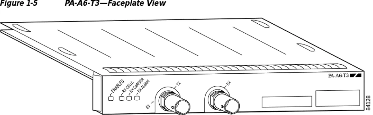
Figure 1-5 PA-A6-T3—Faceplate View
The PA-A6 can be installed on the Cisco 7200 series router, Cisco 7200VXR series router, Cisco 7301 router, Cisco 7401ASR routers, Cisco 7500 series routers using VIP4-50 and VIP4-80, and Cisco 7600 series routers using FlexWAN modules. There are no restrictions on slot locations or sequence; you can install a PA-A6 in any available port adapter slot.
Features
The PA-A6 supports the following features:
• Up to 8191 simultaneously available virtual circuits (VCs)
• Up to 2000 simultaneous segmentations and reassemblies (SARs)
• ATM adaptation layer 5 (AAL5) for data traffic
• Full available bit rate (ABR) support (Traffic Management 4.0), all modes
• Traffic shaping per VC rates from 2.3 kbps to 155 Mbps, in 2.3-kbps increments
• Line rate performance at 256-byte packets on Cisco 7200 series routers
• Line rate performance at 256-byte packets on the Cisco 7200VXR series routers
• Line rate performance at 256-byte packets on Cisco 7301 router
• Line rate performance at 128-byte packets on a Cisco 7401ASR router
• Line rate performance at 256-byte packets on a Cisco 7500 series routers
• Line rate performance at 256-byte packets on a Cisco 7600 series routers
• New ATMizer (ATMizerII+) running at 100 MHz
• Increased SDRAM (32 MB) compared to PA-A3 (4 MB)
• Increased SSRAM (1 MB per SAR) compared to PA-A3 (512 KB per SAR)
• Line rate performance at 64-byte packets on unidirectional traffic with traffic shaping
• IP-to-ATM class of service (CoS)
• Non-real-time variable bit rate (nrt-VBR), unspecified bit rate (UBR), constant bit rate (CBR), and available bit rate (ABR) quality of service (QoS)
• Operation, Administration, and Maintenance alarm indication signal (OAM AIS) cells
• Online insertion and removal (OIR) on Cisco 7200 series router, Cisco 7200VXR series router,
84128
ENABLEDRX CELLSRX CARRIERRX ALARM
E3
TX RX
Chapter 1 Overview LEDs
The PA-A6 supports the following protocols and services:
• User-Network Interface (UNI) signaling
• Integrated Local Management Interface (ILMI)
• RFC-1483
• RFC-1577
The PA-A6 complies with the environment specification listed inTable 1-1.
LEDs
The PA-A6-OC3SMI/SMM/SML port adapters have four status LEDs and one ENABLED LED. (See
Figure 1-6.)
Figure 1-6 LEDs on the PA-A6—Horizontal Orientation
Note PA-A6-E3 and PA-A6-T3 have three status LEDS (RF CELLS, RX CARRIER, RX ALARM). See
Figure 1-4 andFigure 1-5.
After system initialization, the ENABLED LED goes on, indicating that the port adapter has been enabled for operation.
The following conditions must be met before the PA-A6 is enabled:
• The port adapter is correctly connected and is receiving power.
• A valid system software image for the port adapter has been downloaded successfully.
• The system recognizes the port adapter.
If any of these conditions are not met, or if the initialization fails for other reasons, the ENABLED LED does not go on.
Table 1-2lists LED colors and function.
Table 1-1 PA-A6 Port Adapter Specifications
Environmental Specification Description
Operating temperature 50 to 104oF (10 to 40oC)
Humidity 0 to 90%, noncondensing
75785
CLASS 1 LASER PRODUCT LASERPRODUKT DER KLASSE 1PROUIT LASER DE CLASSE 1PRODUCTO LASER CLASS 1
ENABLED RX CELLSRX CARRIERRX ALARMTX CELLS
PA-A6-OC3SMI
155-SMI
RX TX
Chapter 1 Overview Port Adapter Slot Locations on the Supported Platforms
Figure 1-23 Cisco 7613 Router FlexWAN and Enhanced FlexWAN Slot Locations
Note Slot numbering for the Cisco 7613 router with FlexWAN and Enhanced FlexWAN start at the top of the chassis and begin with slot 1(supervisor engine) and go through slot 12, however, slot 3 through slot 7 and slot 9 through slot 12 are used for OSMs (optical service modules. Also, if slot 2 is not used for a redundant supervisor, slot 2 may also be used for OSMs. Slot 7 and slot 8 use Cisco WS-SUP720 modules.
1 Slot 1, reserved for NPE 8 Slot 8—Cisco WS-SUP720
2 Slot 2 reserved for redundant NPE 9 Slot 9—Cisco WS-SUP720
3 Slot 3—OSM 10 Slot 10—port adapter
4 Slot 4—port adapter 11 Slot 11—port adapter
5 Slot 5—port adapter 12 Slot 12—port adapter
6 Slot 6—port adapter 13 Slot 13—blank
7 Slot 7—port adapter
FAN STATUS SUPERVISOR2 WS-X6K-SUP2-2GE STATUS SYSTEMCONSOLEPWR MGMT RESET CONSOLE CONSOLEPORT MODE PCMCIA EJECT PORT 1 PORT 2 Switch Load 100% 1% LINK LINK SUPERVISOR2 WS-X6K-SUP2-2GE STATUS SYSTEMCONSO LE PWR MGMT RESET CONSOLE CONSOLE PORT MODE PCMCIA EJECT PORT 1 PORT 2 Switch Load 100% 1% LINK LINK 1 2 3 4 5 6 7 8 9 10 11 12 13 OC12 POS MM OSM-40C12-POS-MM STATUS 1 2 3 4 RESET
LINK 1 LINK 2 LINK 3 LINK 4 CARRIERALARM ACTIVE TX RXTX PORT 1 RX CARRIERALARM ACTIVETXRXTX PORT 2 RX CARRIERALARM ACTIVETXRXTX PORT 3 RX CARRIERALARM ACTIVE TX RXTX RX OC12 POS MM OSM-40C12-POS-MM STATUS 1 2 3 4 RESET
LINK 1 LINK 2 LINK 3 LINK 4 CARRIERALARM ACTIVETX RXTX PORT 1 RX CARRIERALARM ACTIVETXRXTX PORT 2 RX CARRIERALARM ACTIVETXRXTX PORT 3 RX CARRIERALARM ACTIVE TX RXTX RX OC12 POS MM OSM-40C12-POS-MM STATUS 1 2 3 4 RESET
LINK 1 LINK 2 LINK 3 LINK 4 CARRIER ALARM ACTIVETXRXTX PORT 1 RX CARRIERALARM ACTIVE TX RXTX PORT 2 RX CARRIERALARM ACTIVE TX RXTX PORT 3 RX CARRIERALARM ACTIVETX RXTX RX OC12 POS MM OSM-40C12-POS-MM STATUS 1 2 3 4 RESET
LINK 1 LINK 2 LINK 3 LINK 4 CARRIERALARM ACTIVE TX RXTX PORT 1 RX CARRIERALARM ACTIVE TX RXTX PORT 2 RX CARRIERALARM ACTIVE TX RXTX PORT 3 RX CARRIER ALARM ACTIVETXRXTX RX OC12 POS MM OSM-40C12-POS-MM STATUS 1 2 3 4 RESET
LINK 1 LINK 2 LINK 3 LINK 4 CARRIERALARM ACTIVETX RXTX PORT 1 RX CARRIERALARM ACTIVETXRXTX PORT 2 RX CARRIERALARM ACTIVETXRXTX PORT 3 RX CARRIERALARM ACTIVE TX RXTX RX OC12 POS MM OSM-40C12-POS-MM STATUS 1 2 3 4 RESET
LINK 1 LINK 2 LINK 3 LINK 4 CARRIERALARM ACTIVE TX RXTX PORT 1 RX CARRIERALARM ACTIVETXRXTX PORT 2 RX CARRIERALARM ACTIVETXRXTX PORT 3 RX CARRIERALARM ACTIVE TX RXTX RX OC12 POS MM OSM-40C12-POS-MM STATUS 1 2 3 4 RESET
LINK 1 LINK 2 LINK 3 LINK 4 CARRIERALARM ACTIVETX RXTX PORT 1 RX CARRIERALARM ACTIVETXRXTX PORT 2 RX CARRIERALARM ACTIVETXRXTX PORT 3 RX CARRIERALARM ACTIVE TX RXTX RX SWITCH FABRIC MDL STATUS SELECT NEXT WS-C6500-SFM ACTIVE SWITCH FABRIC MDL STATUS SELECT NEXT WS-C6500-SFM ACTIVE 1 2 3 4 5 6 7 8 9 10 11 12 13 122210