LBNL-50934
E
RNEST
O
RLANDO
L
AWRENCE
B
ERKELEY
N
ATIONAL
L
ABORATORY
Energy Efficiency Improvement
and Cost Saving Opportunities for
Breweries
An ENERGY STAR
®
Guide for Energy
and Plant Managers
Christina Galitsky, Nathan Martin, Ernst Worrell and
Bryan Lehman
Environmental Energy Technologies Division
Sponsored by the U.S. Environmental
Protection Agency
Disclaimer
This document was prepared as an account of work sponsored by the United States Government. While this document is believed to contain correct information, neither the United States Government nor any agency thereof, nor The Regents of the University of California, nor any of their employees, makes any warranty, express or implied, or assumes any legal responsibility for the accuracy, completeness, or usefulness of any information, apparatus, product, or process disclosed, or represents that its use would not infringe privately owned rights. Reference herein to any specific commercial product, process, or service by its trade name, trademark, manufacturer, or otherwise, does not necessarily constitute or imply its endorsement, recommendation, or favoring by the United States Government or any agency thereof, or The Regents of the University of California. The views and opinions of authors expressed herein do not necessarily state or reflect those of the United States Government or any agency thereof, or The Regents of the University of California.
Ernest Orlando Lawrence Berkeley National Laboratory is an equal opportunity employer.
LBNL-50934
Energy Efficiency Improvement and Cost Saving Opportunities
for Breweries
An ENERGY STAR
®Guide for Energy and Plant Managers
Christina Galitsky, Nathan Martin, Ernst Worrell and Bryan Lehman
Energy Analysis Department
Environmental Energy Technologies Division Ernest Orlando Lawrence Berkeley National Laboratory
University of California Berkeley, CA 94720
September 2003
This report was funded by the U.S. Environmental Protection Agency’s Climate Protection Partnerships Division as part of ENERGY STAR. ENERGY STAR is a government-backed program that helps businesses protect the environment through superior energy efficiency. The work was supported through the U.S. Department of Energy Contract No. DE-AC03-76SF00098.
Energy Efficiency Improvement and Cost Saving Opportunities for Breweries An ENERGY STAR® Guide for Energy and Plant Managers
Christina Galitsky, Nathan Martin, Ernst Worrell and Bryan Lehman Energy Analysis Department
Environmental Energy Technologies Division Ernest Orlando Lawrence Berkeley National Laboratory
September 2003
ABSTRACT
Annually, breweries in the United States spend over $200 million on energy. Energy consumption is equal to 3 – 8% of the production costs of beer, making energy efficiency improvement an important way to reduce costs, especially in times of high energy price volatility. After a summary of the beer making process and energy use, we examine energy efficiency opportunities available for breweries. We provide specific primary energy savings for each energy efficiency measure based on case studies that have implemented the measures, as well as references to technical literature. If available, we have also listed typical payback periods. Our findings suggest that given available technology, there are still opportunities to reduce energy consumption cost-effectively in the brewing industry. Brewers value highly the quality, taste and drinkability of their beer. Brewing companies have and are expected to continue to spend capital on cost-effective energy conservation measures that meet these quality, taste and drinkability requirements. For individual plants, further research on the economics of the measures, as well as their applicability to different brewing practices, is needed to assess implementation of selected technologies.
Energy Efficiency Improvement and Cost Saving Opportunities for Breweries
Table of Contents
1. Introduction ... 1
2. The Brewery Market ... 2
3. Process Description ... 5
4. Energy Use ... 9
4.1 Energy Consumption and Expenditures... 9
4.2 Energy Intensity ... 11
5. Options for Energy Efficiency ... 13
6. Process-Specific Measures ... 19
6.1 Mashing and Lauter Tun Processes ... 19
6.2 Wort Boiling and Cooling... 19
6.3 Fermentation ... 24
6.4 Technologies for Beer Processing ... 25
6.5 Technologies for Packaging... 27
7. Cross-cutting Measures ... 28
7.1 Boilers and Steam Distribution... 28
7.2 Motors and Systems that Use Motors ... 31
7.3 Refrigeration and Cooling... 33
7.4 Other Utilities... 35
8. Material Efficiency Opportunities... 39
9. Future Technologies ... 43
10. Summary & Conclusions ... 44
11. Acknowledgements... 47
12. References... 48
Tables Table 1. Major brewery products and shipments value, 1997 ... 3
Table 2. 1994 Primary energy consumption and expenditures in malt beverages... 9
Table 3. Uses and sources of electricity in the brewery sector, 1994... 10
Table 4. Estimated percentage energy use for various brewing processes ... 11
Table 5. Process-specific energy efficiency measures for the brewing industry ... 14
Table 6. Cross-cutting and utilities energy efficiency measures for the brewing industry15 Table 8. Specific primary energy savings and estimated paybacks for process specific efficiency measures ... 45
Table 9. Specific primary energy savings and estimated paybacks for efficiency measures for utilities ... 46
Appendix I. Locations and capacity of large breweries... 56
Appendix II. Employee tasks for energy efficiency ... 57
Appendix III: Energy management system assessment for best practices in energy efficiency... 58
Figures
Figure 1. U.S. Beer production 1980-1999... 2 Figure 2. U.S. brewers’ production 1987-1999 ... 4 Figure 3. Process stages in beer production... 7 Figure 4. Physical primary energy intensities for beer production for selected countries
and companies ... 12 Figure 5. 1998 Energy consumption for German breweries by size... 12 Figure 6. Main elements of a strategic energy management system ... 17
1. Introduction
As U.S. manufacturers face an increasingly competitive global business environment, they seek opportunities to reduce production costs without negatively affecting product yield or quality. Uncertain energy prices in today’s marketplace negatively affect predictable earnings, a concern for publicly-traded companies in the beer industry. For public and private companies alike, increasing energy prices are driving up costs and decreasing their value added. Successful, cost-effective investment into energy efficiency technologies and practices meet the challenge of maintaining the output of a high quality product despite reduced production costs. This is especially important, as energy-efficient technologies often include “additional” benefits, such as increasing the productivity of the company.
Energy efficiency is an important component of a company’s environmental strategy. End-of-pipe solutions can be expensive and inefficient while energy efficiency can often be an inexpensive opportunity to reduce criteria and other pollutant emissions. Energy efficiency can be an effective strategy to work towards the so-called “triple bottom line” that focuses on the social, economic, and environmental aspects of a business.1
Voluntary government programs aim to assist industry to improve competitiveness through increased energy efficiency and reduced environmental impact. ENERGY STAR®, a voluntary program managed by the U.S. Environmental Protection Agency (EPA), stresses the need for strong and strategic corporate energy management programs. ENERGY STAR provides energy management tools and strategies for successful corporate energy management programs. The current report describes research conducted to support ENERGY STAR and its work with the beer industry. This research provides information on potential energy efficiency opportunities for breweries. ENERGY STAR can be contacted through www.energystar.gov for additional energy management tools that facilitate stronger energy management practices in U.S. industry.
1
The concept of the “triple bottom line” was introduced by the World Business Council on Sustainable Development (WBCSD). The three aspects are interconnected as society depends on the economy and the economy depends on the global ecosystem, whose health represents the ultimate bottom line.
2.
The Brewery Market
The U.S. brewery sector (SIC code 2082 or NAICS 312120) is composed of about 500 companies and produces about $20 billion worth of shipments (DOC, 1999). The major product class is canned beer and ale case goods. Production facilities are distributed throughout the country. While production processes have mostly remained unchanged, the sector is increasingly moving to economies of scale. Large establishments with more than 250 employees account for roughly half of the value added in the sector (DOC, 1999). As of 1998, there were 43 large breweries that accounted for the majority of production among the country’s more than 2,000 brewing establishments (see Appendix I) (Real Beer, 2000). The number of breweries is now at the highest level since prohibition ended in 1933 (Hein, 1998), underlining the dynamic development in the malt beverages industry.
Brewery products primarily consist of beer (lager and ale). Figure 1 shows the historical production of beer in the U.S. Production peaked in 1990, in part due to changes in tax regulations that took effect in 1991, adding an excise tax on brewery products. Annual production has ranged around 200 million barrels2 for most of the 1990s.
Figure 1. U.S. Beer production 1980-1999 (million barrels)
205 200 195 190 185 180
Note: Data from 1990-1999 reflect calendar rather than fiscal year data. Source: Beer Institute, 2000. 1999 is an estimate from the Beer Institute.
While U.S. beer production peaked in 1990, the long-term (1980-1999) shows a slightly declining per capita trend. U.S. Beer consumption per capita in 1999 was 22 gallons, down from 23 in 1980. However, trends vary by state (Hein, 1998). Factors that affect
2 A barrel of beer is 31 gallons or 1.2 hectoliters.
M illion ba rr e ls 198 0 198 1 198 2 198 3 198 4 198 5 198 6 198 7 198 8 198 9 199 0 199 1 199 2 199 3 199 4 199 5 199 6 199 7 199 8 199 9
beer consumption are weather (precipitation, temperature), population growth and distribution, economic development and competition with other drinks. Future consumption trends will be affected by competition with other ethanol drinks (wine, spirits) and non-alcoholic drinks. Of these, wine and soft drinks show the highest growth in recent years (Hein, 1998).
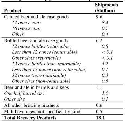
The production of beer in bottles and cans dominates the market. As Table 1 indicates, canned beer accounts for half the value of shipments for the industry, with bottled beer accounting for a third.
Table 1. Major brewery products and shipments value, 1997 Product
Shipments ($billion)
Canned beer and ale case goods 9.6
12 ounce cans 8.4 16 ounce cans 0.7
Other 0.4
Bottled beer and ale case goods 6.2
12 ounce bottles (returnable) 0.8 Less than 12 ounce (returnable) < 0.1 Other sizes (returnable) < 0.1 12 ounce bottles (non-returnable) 4.2 Less than 12 ounce (non-returnable) 0.1 32 ounce (non-returnable) 0.3 Other sizes (non-returnable) 0.6
Beer and ale in barrels and kegs 1.1
One half barrel size 1.0
Other size 0.1
All other brewing products 0.6
Malt beverages, not specified by kind 0.5
Total Brewery Products 18.1
Source: DOC, 1999
Figure 2 identifies production by selected companies between 1987 and 1999. Together, Anheuser-Busch, Miller and Coors companies account for 83% of total U.S. production. Within these companies, the largest selling brands are Budweiser (20% share), Bud Light (14%), Miller Franchise (8%), Coors Light (8%) and Busch (5%). The share of light beer continues to grow and currently has captured a third of the market. While growth in domestic beer production for the main brands has been relatively flat, the craft brewing3 segment of the industry has begun to show stronger growth that should continue, although the base of production is still relatively small (Edgell Communications, 2000). The top five craft brews accounted for less than 3 million barrels (2.6 million hl) in 1999. Imports account for about 7% of the current beer market in the U.S., and continue to grow (Hein, 1998). The main exporters to the U.S. are Mexico, Canada, the Netherlands, United Kingdom, Germany and Ireland. The U.S. beer industry exports beer mainly to
3
Craft brewing is defined here as not more than one-third owned by another large non-craft brewing company of greater than $50 million revenue.
the Asian market (Japan, Taiwan, Hong Kong), the Americas (Brazil, Canada, Mexico) and Russia. Exports were growing until 1995 when they began decreasing, due to the economic developments in Asia, Brazil and Russia.
Value-added reflects the value of shipments less the cost of inputs required for producing the products. Value added in the brewing industry increased at an average of 6.5% per year from $3.7 billion in 1980 to $11.2 billion in 1998 (DOC, 2000). During the same period, employment dropped by 1.6% per year from 43,000 to 32,000 employees. This puts the breweries sector among the top ten industrial sectors in terms of value-added per employee. The decreased employment in the U.S. brewery sector may suggest an increasing level of mechanization.
Figure 2. U.S. brewers’ production (million barrels) 1987-1999
120 100 80 60 Anheuser-Busch Miller Coors Stroh Heileman Pabst Others 40 20 0
Source: Edgell Communications, 2000; Hardwick, 1994
P ro d u c ti o n ( M illio n b a rr e ls ) 198 7 198 9 199 1 199 3 199 5 199 7 199 9
3. Process
Description
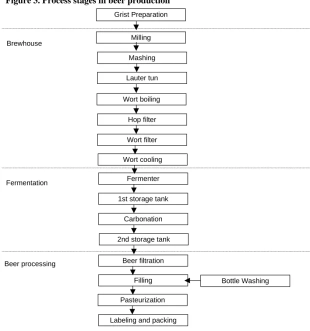
The brewing process uses malted barley and/or cereals, unmalted grains and/or sugar/corn syrups (adjuncts), hops, water, and yeast to produce beer. Most brewers in the U.S. use malted barley as their principal raw material. Depending on the location of the brewery and incoming water quality, water is usually pre-treated with a reverse osmosis carbon filtration or other type of filtering system. Figure 3 outlines the main stages of production for U.S. breweries.
The first step of brewing, milling and carbon filtration, takes place when malt grains are transported from storage facilities and milled in a wet or dry process to ensure that one can obtain a high yield of extracted substances (UNEP, 1996). Sometimes the milling is preceded by steam or water conditioning of the grain.
The mixture of milled malt, gelatinized adjunct and water is called mash. The purpose of mashing is to obtain a high yield of extract (sweet wort) from the malt grist and to ensure product uniformity. Mashing consists of mixing and heating the mash in the mash tun, and takes place through infusion, decoction or a combination of the two. During this process, the starchy content of the mash is hydrolyzed, producing a liquor called sweet wort. In the infusion mashing process, hot water between 160-180°F (71-82°C) is used to increase the efficiency of wort extraction in the insulated mashing tuns. The mashing temperature is dictated by wort heating using steam coils or jackets. In decoction mashing, a portion of the mashing mixture is separated from the mash, heated to boiling and re-entered into the mash tun. This process can be carried out several times, and the overall temperature of the wort increases with each steeping. Part of this mash is evaporated. This process requires an estimated 12-13 kBtu/barrel4 for medium-sized breweries (Hackensellner, 2000). The type of mashing system used depends on a number of factors such as grist composition, equipment and type of beer desired, although decoction mashing appears to be the preferred system in North America (Hardwick, 1994). Infusion mashing is less energy intensive than decoction mashing requiring roughly 8-10 kBtu/barrel of fuel (Hackensellner, 2000).
Following the completion of the mash conversion, the wort is separated from the mash. The most common system in large breweries is a lauter tun or a mash filter (O’Rourke, 1999b). A more traditional system is the use of a combined mash tun/lauter tun, usually termed a mashing kettle or vessel. In the combined mashing vessel, the wort run off is directed through a series of slotted plates at the bottom of the tun. The mash floats on top of the wort. This tends to be the slowest wort separation system although it is the lowest cost in terms of capital outlay (O’Rourke, 1999b). With the use of the lauter tun, the converted mash is transferred to a lautering vessel where the mash settles on a false bottom and the wort is extracted. Lautering is a complex screening procedure that retains the malt residue from mashing on slotted plates or perforated tubes so that it forms a
4
In the U.S., energy use in beer brewing is commonly expressed in kBtu/barrel. To convert from kBtu (higher heating value, HHV) to MJ multiply by 1.055 MJ/kBtu. To convert from barrels of beer to hectoliter (hl) divide by 0.85 barrel/hl.
filtering mass. The wort flows through the filter bed (Hardwick, 1994). In both the combined mashing vessel and the lauter tun, the grains are also sparged (i.e. sprayed and mixed) with water to recover any residual extract adhering to the grain bed. The extracted grain, termed “spent grain,” is most often used as animal feed. In a mash filter, the mash is charged from the mash mixer. The filter is fitted with fine pore polypropylene sheets that forms a tight filter bed and allows for very high extract efficiency (in excess of 100% laboratory extract) (O’Rourke, 1999b). However, the quality of the filtered wort may be affected through the use of a mash filter process and may not be applicable for all types of brewing.
The next step, wort boiling, involves the boiling and evaporation of the wort (about a 4-12% evaporation rate) over a 1 to 1.5 hour period. The boil is a strong rolling boil and is the most fuel-intensive step of the beer production process. Hackensellner (2000) estimates 44 to 46 kBtu/barrel is used for conventional wort boiling systems in Germany. The boiling sterilizes the wort, coagulates grain protein, stops enzyme activity, drives off volatile compounds, causes metal ions, tannin substances and lipids to form insoluble complexes, extracts soluble substances from hops and cultivates color and flavor. During this stage, hops, which extract bitter resins and essential oils, can be added. Hops can be fully or partially replaced by hop extracts, which reduce boiling time and remove the need to extract hops from the boiled wort. If hops are used, they can be removed after boiling with different filtering devices in a process called hop straining. As with the spent mashing grains, some breweries sparge the spent hops with water and press to recover wort. In order to remove the hot break, the boiled wort is clarified through sedimentation, filtration, centrifugation or whirlpool (being passed through a whirlpool tank). Whirlpool vessels are most common in the U.S.
After clarification, the cleared hopped wort is cooled. Cooling systems may use air or liquids as a cooling medium. Atmospheric cooling uses air stripping columns (used by Anheuser-Busch) while liquid cooling uses plate heat exchangers. Heat exchangers are of two types: single-stage (chilled water only) or multiple-stage (ambient water and glycol). Wort enters the heat exchanger at approximately 205 to 210ºF (96-99ºC) and exits cooled to pitching temperature. Pitching temperatures vary depending on the type of beer being produced. Pitching temperature for lagers run between 43-59ºF (6-15°C), while pitching temperatures for ales are higher at 54-77ºF (12-25°C) (Bamforth, 2001). The amount of heat potentially recovered from the wort during cooling by a multiple stage heat exchanger is 35-36 kBtu/barrel (Hackensellner, 2000). Certain brewers aerate the wort before cooling to drive off undesirable volatile organic compounds. A secondary cold clarification step is used in some breweries to settle out trub, an insoluble protein precipitate, present in the wort obtained during cooling.
Once the wort is cooled, it is oxygenated and blended with yeast on its way to the fermentor.5 The wort is then put in a fermentation vessel. For large breweries, the cylindrical fermentation vessels can be as large as 4,000-5,000 barrel tanks (Bamforth, 2001). During fermentation, the yeast metabolizes the fermentable sugars in the wort to produce alcohol and carbon dioxide (CO2). The process also generates significant heat
that must be dissipated in order to avoid damaging the yeast. Fermenters are cooled by coils or cooling jackets. In a closed fermenter, CO2 can be recovered and later reused.
Fermentation time will vary from a few days for ales to closer to 10 days for lagers (Bamforth, 2001). The rate is dependent on the yeast strain, fermentation parameters (like the reduction of unwanted diacetyl levels) and taste profile that the brewer is targeting (Bamforth, 2001; Anheuser Busch, 2001).
Figure 3. Process stages in beer production
Grist Preparation Milling Brewhouse Beer processing Mashing Lauter tun Wort boiling Hop filter Wort filter Wort cooling Fermenter 1st storage tank Carbonation 2nd storage tank Beer filtration Pasteurization Filling
Labeling and packing
Bottle Washing
Source: UNIDO, 2000
At the conclusion of the first fermentation process, yeast is removed by means of an oscillating sieve, suction, a conical collector, settling or centrifugation. Some of the yeast is reused while other yeast is discarded. Some brewers also wash their yeast. Some brewing methods require a second fermentation, sometimes in an aging tank, where sugar or fresh, yeasted wort is added to start the second fermentation. The carbon dioxide
produced in this stage dissolves in the beer, requiring less carbonation during the carbonation process. Carbonation takes place in the first fermentation also. Yeast is once again removed with either settling or centrifugation.
Beer aging or conditioning is the final step in producing beer. The beer is cooled and stored in order to settle yeast and other precipitates and to allow the beer to mature and stabilize. For beers with a high yeast cell count, a centrifuge may be necessary for pre-clarification and removal of protein and tannin material (UNEP, 1996). Different brewers age their beer at different temperatures, partially dependent on the desired taste profile. According to Bamforth (1996), ideally, the beer at this stage is cooled to approximately 30ºF (-1°C), although this varies in practice from 30°F to 50°F (-1°C to 10°C) (Anheuser Busch, 2001). Beer is held at conditioning temperature for several days to over a month and then chill proofed and filtered. A kieselguhr (diatomaceous earth) filter is typically used to remove any remaining yeast. Brewers use stabilizing agents for chill proofing. Coloring, hop extracts and flavor additives are dosed into the beer at some breweries. The beer’s CO2 content can also be trimmed with CO2 that was collected during fermentation.
The beer is then sent to a bright (i.e. filtered) beer tank before packaging. In high gravity brewing (see also discussion in efficiency measures section), specially treated water would be added during the conditioning stage. This can be a significant volume, as high as 50% (Anheuser Busch, 2001).
Finally, the beer must be cleaned of all remaining harmful bacteria before bottling. One method to achieve this, especially for beer that is expected to have a long shelf life, is pasteurization, where the beer is heated to 140°F (60°C) to destroy all biological contaminants. Different pasteurization techniques are tunnel or flash pasteurization. Energy requirements for pasteurization can vary from 19-23 kWh per 1000 bottles for tunnel pasteurization systems (Hackensellner, 2000). Other estimates are 14-20 kBtu/barrel (Anheuser Busch, 2001). An alternative approach is the use of sterile filtration (Bamforth, 2001). However, this technology is new, and some believe these systems may require as much extra energy as they save (Todd, 2001).
A large amount of water is used for cleaning operations. Incoming water to a brewery can range from 4 to 16 barrels of water per barrel of beer, while wastewater is usually 1.3 to 2 barrels less than water use per barrel of beer (UNEP, 1996). The wastewater contains biological contaminants (0.7-2.1 kg of BOD/barrel).6 The main solid wastes are spent grains, yeast, spent hops and diatomaceous earth. Spent grains are estimated to account for about 16 kg/barrel of wort (36 lbs/barrel), while spent yeast is an additional 2-5 kg/barrel of beer (5-10 lbs/barrel) (UNEP, 1996). These waste products primarily go to animal feed. Carbon dioxide and heat are also given off as waste products.
6
BOD or Biological Oxygen Demand reflects a measure of the concentration of organic material. BOD, unless otherwise indicated, is measured for a five day period (UNEP, 1996)
--
--4.
Energy Use
4.1 Energy Consumption and Expenditures
The Food and Kindred Products group (SIC 20) consumed roughly 1585 TBtu (1.7 MJ)7, equal to roughly 7% of total manufacturing primary energy in 1994 (EIA, 1997). Of the food processing energy use, breweries consumed about 4%, equal to 67 TBtu (0.7 million TJ) and 40% of the beverage manufacturing energy, which also includes sectors such as soft drinks, wineries and distilleries.
Natural gas and coal account for about 60% the total primary energy consumed by the malt beverages industry. These fuels are primarily used as inputs to boilers to produce steam for various processes and to generate onsite electricity (see Table 2). Other uses include direct process uses, such as process heating, cooling, refrigeration and machine drive, and direct non-process uses such as facility heating. Net electricity consumption, including generation losses, was 36% of primary energy requirements (see Table 2).
Total energy expenditures for malt beverages in 1994 were $221 million, with electricity accounting for 56% of expenditures, even though net electric energy consumption, including losses, is 36% (EIA, 1997). 1998 data from the Annual Survey of Manufactures shows that expenditures remained relatively constant at $210 million—even though output increased—with electricity’s share at 58% (DOC, 2000). Although overall energy expenditure data exist for more recent years, 1994 is the last year when detailed energy consumption and energy expenditure statistics were published for the breweries sector by the Energy Information Administration (EIA, 1997 and 2001). In the United Kingdom, energy expenditures account for roughly 3-8% of total production costs (Sorrell, 2000; McDonald, 1996). Anheuser-Busch suggests that energy expenditures account for about 8.5% (Anheuser-Busch, 2001). The largest production costs are packaging materials, raw production materials (grains) and malt (Sorrell, 2000).
Table 2. 1994 Primary energy consumption8 and expenditures in malt beverages Consumption Expenditures
TBtu (%) $Million (%)
Net electricity (purchased) 8 12% 123 56%
Electricity losses 16 24%
Distillate fuel oil 0 0% 0.5 0%
Natural gas 22 33% 59 27%
Coal 17 25% 28 13%
Other fuels 4 6% 11 5%
Total 67 100% 221 100%
Source: EIA, 1997
7 To convert from TBtu (higher heating value, HHV) to TJ multiply by 1.055*10-9 TJ/TBtu.
8 Final energy is the purchased energy by the final user (or plant). Primary energy is calculated using the average efficiency for public power generation to estimate the fuels used to generate the power consumed by the brewing industry. We use an average efficiency of 32% based on U.S. consumption of fuels at power plants. Hence, primary energy is roughly three times final energy.
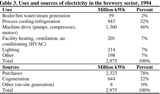
The relative importance of electricity costs, in addition to the high steam demand in the sector, prompted investment into the generation of onsite electricity at various manufacturing facilities. Cogenerated electricity (the production of both heat and power, also called combined heat and power or CHP) in 1994 was 644 million kWh (EIA, 1997). Accounting for all of the electricity uses (net demand), cogenerated electricity accounts for 22% of the total electricity used onsite9. This share of cogenerated electricity is relatively high compared to other industries in the U.S. The largest uses of electricity are in machine drives for the use of pumps, compressed air, brewery equipment, and process cooling (see Table 3).
Table 3. Uses and sources of electricity in the brewery sector, 1994
Uses Million kWh Percent
Boiler/hot water/steam generation
Process cooling/refrigeration
Machine drive (pumps, compressors,
motors)
Facility heating, ventilation, air
conditioning (HVAC) Lighting Other Total 59 2% 943 32% 1,360 46% 201 7% 214 7% 198 7% 2,975 100%
Sources Million kWh Percent
Purchases 2,323 78%
Cogeneration 644 22%
Other (on-site generation) 8 0%
Total 2,975 100%
Source: EIA, 1997
Table 4 identifies energy use for specific brewery processes based on surveys conducted by the Energy Technology Support Unit (ETSU) in the United Kingdom for a kegging brewery (Sorrell, 2000). As the table indicates, the vast majority of thermal energy is used in brewing operations and pasteurization, while electricity consumption is more evenly divided among fermentation, beer conditioning and space and utilities. Anheuser-Busch estimates that 64% of thermal energy is used in brewing (Meyer, 2001).
9
Net demand accounts for the total uses of electricity onsite and reflects the fact that some of the purchased fuels are used to produce electricity for internal consumption. In 1994, net electricity use (purchases) was 8 TBtu (2,311 Million kWh) while net demand was 10 TBtu (2,975 Million kWh).
Table 4. Estimated percentage energy use for various brewing processes
Thermal Energy Brewhouse 30-60%
Packaging 20-30%
Space heating <10%
Utilities 15-20%
Electrical Energy Refrigeration 30-40%
Packaging 15-35% Compressed air 10% Brewhouse 5-10% Boiler house 5% Lighting 6% Other 10-30% Source: Sorrell, 2000 4.2 Energy Intensity
Energy intensity, or specific energy consumption, reflects the amount of energy required per unit of output or activity. Barring changes in the composition of output, declining energy intensities can reflect technology improvements. In the breweries sector, energy intensity can be measured using both physical and economic indicators as the output denominator. Figure 4 depicts average physical primary energy intensities for beer production for the U.S. and other countries (The electricity consumption includes losses in transmission and distribution.).
As Figure 4 indicates, there is a wide range of unit energy consumption for the various countries. U.S. national data is based on 1991 and 1994 Energy Information Administration energy data and output data provided by the Beer Institute (EIA, 1994 and 1997; Beer Institute, 2000). (Brewery energy consumption was not reported in the most recent EIA energy survey for 1998.) In addition to U.S. national data, we included a time series for Anheuser-Busch data (Anheuser-Busch, 2001) and for Coors data (Coors, 2001), which combined produce over 60% of the beer in the U.S.
The variation in intensities is partly influenced by the type of product being produced. In the United Kingdom for example, almost 80% of beer produced is draught beer that has much lower energy requirements than other types of beer since it is not pasteurized (Lom and Associates, 1998). Intensities will also vary depending on the size of the brewery. Figure 5 depicts the range of specific energy consumption (in kBtu/barrel) for German breweries of various sizes. Class V contains the largest breweries (greater than 500,000 hectoliters (hl) annual production) and has the lowest specific energy consumption.
Figure 4. Physical primary energy intensities for beer production for selected countries and companies (kBtu/barrel)
500 Canada Speci fi c Energ y C o ns um pti o n (SEC [Kbtu/ ba rrel ] 450 Asahi (Japan) U.S. 400 Anheuser-Busch (US) 350 Coors (US) Germany 300 Austria 250 United Kingdom 0 99 1 2 199 4 1 199 6 99 1998 2000
Note: Primary intensity reflects the accounting of transmission and distribution losses in electricity use. We use a factor of 3.08 to convert final electricity consumption to primary electricity consumption.
Sources: U.S. (EIA, 1997; Beer Institute, 2000), 1998 brewery energy consumption was not reported for 1998 (EIA, 2001); Coors (U.S.) (Coors, 2001); Anheuser-Busch (Anheuser-Busch, 2001); Canada (Lom and Associates, 1998; Nyboer and Laurin, 2001); Austria (EC, 1998; Bkontakt, 2000); Asahi in Japan (Asahi Breweries, 2000); U.K. (Sorrell, 2000); Germany (Hackensellner, 2000)
Figure 5. 1998 Energy consumption for German breweries by size
700 600 500 400 Losses 300 Electricity Fuel 200 100 0
Class I Class II Class III Class IV Class V All (0-20k) (20-50k) (50-100k) (100-500k) (>500k)
Size (hL) Source: Schu et al., 2001
Energy I n tensit y K b tu /b a rre l
5.
Options for Energy Efficiency
A variety of opportunities exist within breweries to reduce energy consumption while maintaining or enhancing the product quality and productivity of the plant. Improving energy efficiency in a brewery should be approached in several ways. First, breweries use equipment such as motors, pumps and compressors. These require regular maintenance, proper operation and replacement with more efficient models, when necessary. Thus, a critical element of plant energy management involves the careful control of cross-cutting equipment that powers the production of a plant. A second and equally important area is the proper and efficient operation of the process. Process optimization and ensuring the most productive technology is in place are key to realizing energy savings in a plant’s operation.
If a company operates several breweries, energy management can be more complex than just considering the needs of a single plant. Whether for a single plant or an entire corporation, establishing a strong organizational energy management framework is important to ensure that energy efficiency measures are implemented effectively.
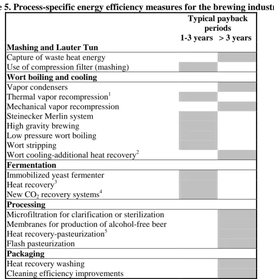
Table 5 lists energy efficiency measures that have been identified as process-specific to mashing, wort boiling and cooling, fermentation, processing and packaging. Table 6 lists measures that are cross-cutting, i.e. they affect many operations, or that concern utilities, such as the production of steam or electricity or cooling. The payback period estimates are based on the implementation of individual technologies. Combining several technologies in a single project or changing management practices may reduce the costs and hence improve the productivity of an investment.
Table 5. Process-specific energy efficiency measures for the brewing industry Typical payback
periods 1-3 years > 3 years Mashing and Lauter Tun
Capture of waste heat energy Use of compression filter (mashing)
Wort boiling and cooling
Vapor condensers
Thermal vapor recompression1
Mechanical vapor recompression Steinecker Merlin system High gravity brewing Low pressure wort boiling Wort stripping
Wort cooling-additional heat recovery2
Fermentation
Immobilized yeast fermenter
Heat recovery3
New CO2 recovery systems4
Processing
Microfiltration for clarification or sterilization Membranes for production of alcohol-free beer
Heat recovery-pasteurization5
Flash pasteurization
Packaging
Heat recovery washing
Cleaning efficiency improvements Notes:
1. Payback period may be longer; 2. Payback period depends on systems used currently and could be shorter; 3. Payback period depends on makeup/exhaust airflow, weather conditions and electricity rates; 4. Small water pump size and low cost of purchased CO2 would create a longer payback period; 5. Payback periods based on a retrofit (Anheuser-Busch, 2001).
Table 6. Cross-cutting and utilities energy efficiency measures for the brewing industry
Typical payback
periods
Measure <2 years >2 years
Boilers and Steam distribution
Maintenance
Improved process control1
Flue gas heat recovery Blowdown steam recovery Steam trap maintenance
Automatic steam trap monitoring Leak repair
Condensate return2
Improved insulation of steam pipes3
Process integration
Motors and Systems that Use Motors
Variable speed drives4
Downsizing of motors, pumps, compressors2
High efficiency motors, pumps, compressors2
Refrigeration and cooling
Better matching of cooling capacity and cooling loads Improved operation of ammonia cooling system Improve operations and maintenance
System modifications and improved design
Insulation of cooling lines5
Other utilities
Lighting
Reduce space heating demand
Anaerobic waste water treatment2
Membrane filtration wastewater
Control and monitoring systems2
Combined heat and power
CHP combined with absorption cooling Engine-driven chiller systems
Notes:
1. Payback period depends on tuning conditions of existing systems; 2. Payback periods may be longer; 3. Payback periods depend on existing conditions; 4. Savings depend on how often the motor is run at less than full speed; 5. Payback period varies depending on purging of the system before and how careful the operators performed pumpouts (Anheuser-Busch, 2001).
The values presented in the following review provide an average estimate or a set of specific data points; only a detailed study of a specific location can produce reliable estimates for that plant. Actual energy savings will likely vary by plant size and operation characteristics. Throughout our review, where possible, we provide an estimate of the range of savings found under varying conditions. We acknowledge that for some measures, particularly new technologies, there may not be sufficient information (e.g. a larger set of experiences) to estimate average industry savings and payback. For these, we have provided the information that was available. We also acknowledge that payback
periods vary from country to country and from brewery to brewery and that a measure may have been adopted by some individual breweries but not all of them. In addition, for those measures only reducing electricity or gas consumption, payback periods will vary with utility rates. To account for these differences in payback periods, we sought comments from U.S. brewers, adapted the data to U.S. conditions where feasible and adjusted our ranges to incorporate their experiences.
Although technological changes in equipment can help to reduce energy use, changes in staff behavior and attitude also can have a great impact. Staff should be trained in both skills and the company’s general approach to energy efficiency for use in their day-to-day practices. Personnel at all levels should be aware of energy use and objectives for energy efficiency improvement. Often this information is acquired by lower level managers but not passed to upper management or to other staff (Caffal, 1995). Programs with regular feedback on staff behavior, such as reward systems, have had good results. Though changes in staff behavior, such as switching off lights or closing windows and doors, save only small amounts of energy at a time, when taken continuously over longer periods, they may have a much greater effect than more costly technological improvements. Most importantly, companies need to institute strong energy management programs that oversee energy efficiency improvement across the corporation. An energy management program will ensure all employees actively contribute to energy efficiency improvements.
Participation in voluntary programs like the EPA ENERGY STAR program, or implementing an environmental management system such as ISO 14001 can help companies track energy and implement energy efficiency measures. One ENERGY STAR partner noted that combining the energy management program with the ISO 14001 program had a large effect on saving energy at their plants.
5.1. Energy Management Systems.
Energy management systems (EMS) and programs. Changing how energy is managed by implementing an organization-wide energy management program is one of the most successful and cost-effective ways to bring about energy efficiency improvements.
An energy management program creates a foundation for improvement and provides guidance for managing energy throughout an organization. In companies without a clear program in place, opportunities for improvement may be unknown or may not be promoted or implemented because of organizational barriers. These barriers may include a lack of communication among plants, a poor understanding of how to create support for an energy efficiency project, limited finances, poor accountability for measures or perceived change from the status quo. Even when energy is a significant cost for an industry, many companies still lack a strong commitment to improve energy management.
EPA, through ENERGY STAR, has worked with many of the leading industrial manufacturers to identify the basic aspects of an effective energy management program.10 The major elements are depicted in Figure 6.
Figure 6. Main elements of a strategic energy management system
A successful program in energy management begins with a strong commitment to continuous improvement of energy efficiency. This typically involves assigning oversight and management
duties to an energy director, establishing an energy policy, and creating a cross-functional energy team. Steps and procedures are then put in place to assess performance, through regular reviews of energy data, technical assessments and benchmarking. From this assessment, an organization is then able to develop a baseline of performance and set goals for improvement.
Performance goals help to shape the development and implementation of an action plan. An important aspect for ensuring the successes of the action plan is involving personnel throughout the organization. Personnel at all levels should be aware of energy use and goals for efficiency. Staff should be trained in both skills and general approaches to energy efficiency in day-to-day practices. In addition, performance results should be regularly evaluated and communicated to all personnel, recognizing high performers. Some examples of simple employee tasks are outlined in Appendix II.
Evaluating performance involves the regular review of both energy use data and the activities carried out as part of the action plan. Information gathered during the formal review process helps in setting new performance goals and action plans and in revealing best practices. Establishing a strong communications program and seeking recognition for accomplishments are also critical steps. Strong communication and recognition help to build support and momentum for future activities.
A quick assessment of an organization’s efforts to manage energy can be made by comparing the current program against the table contained in Appendix II.
Energy monitoring systems.
Energy monitoring and process control systems can play important roles in energy management and in reducing energy use. These may include sub-metering, monitoring and control systems. They can reduce the time required to perform complex tasks, often improve product and data quality and consistency and optimize process operations. Typically, energy and cost savings are around5% or more for many industrial applications of process control systems. These savings apply to plants without updated process control systems; many U.S. plants may already have modern process control systems in lace to improve energy efficiency.
Support for a business energy management program can come from outside sources as well. Some utility companies work with industrial clients to achieve energy savings. In these cases, utility personnel work directly with managers onsite to better identify and implement programs and measures that are more effective for the particular situation of the facility.
6.
Process-Specific Measures
Table 5 lists the process specific measures that we have identified for the beer brewing industry along with their typical payback periods. Below, we describe each of the measures in more detail.
6.1 Mashing and Lauter Tun Processes
Capture of waste heat energy
In the mashing process, waste heat can be captured from the mash or from the hot water tank. This heat can be used for either mashing or for other processes. Some breweries use a hot water tank of roughly 170ºF (75°C) to inject the water into mashing operations. This tank has an overflow stream that can be used during pasteurization to heat the water to 140ºF (60°C). If more heat is needed, steam or hot water can be blended to make water at the temperature needed (UNIDO, 2000). Hackensellner (2000) notes that steam at a temperature of 340ºF (170°C) is used to heat the mash vessel. However, hot water of 200-210ºF (95-98°C) generated from heat recovery can be used to partially heat the mash thereby reducing steam or hot water generation requirements at the facility. The mash tun needs to be refitted with a heat transfer area to recover this waste heat.
Use of compression filter in mashing process
The Brand brewery (the Netherlands), with annual production of about 1 million hl (0.9 million barrels) replaced a plate filter with a compression filter in its mashing process. The compression filter reduces cleaning costs by reducing the need to rinse the filter with water (since it is cleaned by air). The process also increased yield and reduced water use. Energy savings for this measure were 16 billion Btu (16.8 TJ) of gas (lower heating value), or 18.6 kBtu/barrel (16.8 MJ/hl) (NOVEM, 1999a). The cost of the installation of the filter was $620,000 (1.3 million DFl) and the payback period was about 2 years. Proponents of this measure claim that the use of mash filter technology can reduce cycle times, reduce spent grain moisture, increase wort concentration (particularly important for high gravity brewing), and increase the number of brews per day to up to 12 (Stewart, 1999). We acknowledge that while this technology is new and its adoption will take time, sufficient data are not yet available to support all claims and potential impact on taste must be further evaluated.
6.2 Wort Boiling and Cooling
Heat recovery using vapor condensers
Given the high fuel requirements for wort boiling in breweries, several opportunities exist to recover thermal energy and use it in various brewery operations. High-grade heat may be recovered from kettle vapors using either spray condensers or heat exchangers (Sorrell, 2000). The heat from the vapor can be used to pre-heat the incoming wort, while the heat from the vapor condensate can be used to produce hot water for cleaning, space heating, keg washing or other applications in the brewery. Such systems can recover up to 60% of the energy required for wort boiling (Sorrell, 2000).
In 1991, a Grolsch brewery (the Netherlands) installed a waste heat recovery system in its continuous wort boiling operations. Overall energy savings were 35 billion Btu. The
system also reduced water, maintenance and operation costs. The payback period for the energy savings alone was 3.5 years, however, if water and operation and maintenance costs are included, the payback period was 2 years (NOVEM, 1991a). In a related technology, the Bavaria brewery in Lieshout (the Netherlands) installed a system in which the wort vapor is mixed with the steam from the heating coils. The mixture is fed to a condenser and the condensation heat is used to heat a water circuit, which provides heat to the wort pre-heaters as well as to several other departments like filtering and bottling divisions. Net savings from the system are 1,144,000 m3/year natural gas equivalent (i.e. natural gas savings of 1,171,700 m3 but an increased electricity use of 72,000 kWh/year). This translates into a net savings 22 kBtu/barrel (0.02 GJ/hl). The project had a payback period of 5.5 years (CADDET, 1993a; NOVEM, 1993a). A Japanese brewery that installed wort pan condensers to recover condensate as hot water was able to reduce significantly annual steam use. Steam savings resulted from shortening the wort heating time by preheating the incoming wort (900 tons), reducing the steam input into the wort pan container hot water tank steam inline heater (670 tons), and by reducing mixing time. Savings were estimated to be 1.3% of steam consumption (UNIDO, 1995). Heat recovery from kettle and wort boiling and wort cooling in the New Belgium Brewing Company (Colorado) generates enough hot water for all brewing and some cleaning requirements (Farrell, 1998; Heyse et al, 1996; and UNIDO, 2000).
Wort boiling using thermal vapor recompression
Vapor recompression is an established technology for reducing energy costs in evaporation. In a vapor recompression system, the wort is boiled externally to 216ºF (102°C) using compressed vapors up to 1.25 bar. In thermal vapor recompression, a portion of the evaporated water vapor is compressed by high-pressure steam and reused. The wort expands in the kettle at 212ºF (100°C). Vapor-condensate is collected in the condensate tank and the heat (used to preheat water) is recovered through a plate heat exchanger (UNIDO, 2000). These systems work best when operating under constant running conditions for long periods (Sorrell, 2000). Thermal recompression plants have been operating in breweries since 1991. Thermal recompression provides for less costly machinery than straight steam heated designs but requires higher pressure steam (Dedert, 2001). In a thermal vapor recompression system by Huppmann, a portion of the vapors (20-40%) is condensed for hot water generation and a portion (60-80%) is sucked into the steam jet compressor being forced by steam of at least 6 bar pressure. The discharge steam at 1.3-1.4 bar is used to then heat the external boiler (Hackensellner, 2000). Energy requirements for operating the thermal vapor compressor are estimated at 120 kBtu per barrel of evaporated water (Hackensellner, 2000). A disadvantage of this system is that condensate cannot be sent back to the steam plant as it is contaminated by the vapors given off by the wort (Sorrell, 2000). There are however, vapor condensate purification systems that have been shown to have a payback period of two years (Hackensellner, 2000).
In a variation on this technology, the Löwenbrauerei in Schwaebish Hall (Germany) installed a low pressure (0.8 bar) steam vapor recompression 300 hl brew kettle with an interior cooker along with computer automation (Klein-Carl and Reichert, 1991). This study showed the system saved a significant amount of energy (40%) increasing the
efficiency of the heat transfer, reducing the need for a circulation pump and reducing boiling times (Klein-Carl and Reichert, 1991). Primary energy requirements for generating steam for the milling, mashing, and wort boiling are reduced to 27 kBtu/barrel (6.7 kWh/hl), a savings of 16-18 kBtu/barrel (4-4.5 kWh/hl) (Klein-Carl and Reichert, 1991; Heyse et al. 1996).
Wort boiling using mechanical vapor recompression
Vapor recompression is an established technology to reduce energy costs for evaporation. In a vapor recompression system, the wort is boiled to 216ºF (102°C) externally using compressed vapors up to 1.25 bar. The wort expands in the kettle at 212ºF (100°C). Vapor condensate is collected in the condensate tank and the heat (used to preheat water) is recovered through a plate heat exchanger (UNIDO, 2000). Mechanical vapor recompression (MVR) systems have been used in breweries since 1980 and can achieve energy savings because the generated useful heat contains more energy than the electricity required to compress the steam (Hackensellner, 2000; Kidger, 2001). MVR systems work best when operating constantly for long periods (Sorrell, 2000). Manufacturers claim MVR systems reduce the aroma emissions almost entirely, provide a gentle boiling process by lowering the pressure of the compressed vapor and in many cases, significantly reduce or eliminate other steam requirements (Steineker, 2001).
In MVR, the evaporator components are similar to steam-powered machinery with the addition of a mechanical compressor. Mechanical energy supplied via a compressor or fan compresses the vapor to a higher pressure where it may be reused. Vapor from the wort kettle is drawn in by a compressor and compressed by 0.25-0.4 bar above atmospheric pressure. The compressed vapor can be reused for heating an external or internal boiler (Hackensellner, 2000). Steineker notes a reduction in evaporation requirements from 9.9% for conventional boiling to 8.7% for MVR, and estimates fuel consumption as low as 14 kBtu/barrel (Steineker, 2001; Weinzierl et al., 2000). However, MVR systems will have increased electricity requirements to run the compressor and circulating wort pump. Electricity consumption is estimated to range from 0.3 to 2.8 kWh/barrel (0.1 to 0.7 kWh/hl) evaporate (Hackensellner, 2000; Weinzierl et al., 2000). One of the main operating challenges is to maintain an air-free system for wort boiling. This evaporator is generally more costly than thermal vapor recompression, but operating costs are significantly less. Estimates for operating costs are around 2-7% of the investment costs (Hackensellner, 2000).
Steineker Merlin wort boiling system
The Merlin wort boiling system is an external wort boiling system. It is designed such that the wort is contained in a whirlpool holding vessel and is continuously fed into a steam heated cone container. It consists of a whirlpool and an evaporation vessel with boiling equipment whereby the wort passes through both vessels in a circulatory loop (Steineker, 2001). The increased surface area and exposure of the wort to heat limits the required evaporation. Steineker claims that the system has a total evaporation requirement of 4% (compared to 8% in conventional systems), and reduces fuel requirements by up to 65-75%. In addition to energy savings, proponents claim the Merlin system improves product quality with reduced carmelization and reduced fobbing,
provides more brews between cleanings and realizes better vessel utilization (O’Rourke, 1999a; Weinzierl et al., 2000). Potential impacts on beer taste would reduce effectiveness of this measure. An operable system for a 370 hl (315 barrel) operation was installed in the Flensburg Brewery (Germany) in 2000, but no systems have yet been installed in the United States. An analysis of the Scherdel brewery in Hof (Germany) found a savings potential of 31 kBtu/barrel compared to a wort boiling system without heat recovery from the boiling vapors (Steineker, 2001). Another analysis of the Merlin system found fuel consumption of 22 kBtu/barrel, compared to 36 kBtu/barrel for conventional systems (Weinzierl et al., 2000). When an energy storage unit is added to the Merlin system, fuel use drops further to 12.3 kBtu/barrel, for a total savings of 23.7 kBtu/barrel. In all cases, electricity use increases to 0.02 kWh/barrel (Stippler and Felgentraeger, 1999; Weinzierl et al., 2000). As of last year, there were at least four operating Merlin plants worldwide and more expected to be built. Depending on energy prices, paybacks for the installation of a system can be as low as 2 years (Finkeldey, 2001).
Brewing at high specific gravity
Specific gravity is the “heaviness” of a substance compared to water. Beer may be brewed at a higher specific gravity and diluted with water after final filtration to bring it to the desired alcohol concentration (Hardwick, 1994; Sorrell, 2000). Claims of energy savings vary between 18% and 30% in the brewhouse (Sorrell, 2000; Muller, 1996). This technology was first applied in the U.S. right after the Second World War (Muller, 1996). Now it has become a standard technology in the large and some of the medium-sized breweries. In North America today, more beer is produced by high gravity brewing than through conventional means (Stewart, 1999). High gravity brewing can defer capital expenditures, may increase brewing capacity (with more efficient use of plant facilities) and may improve product quality (better consistency and character have been reported, although the impact on flavor is an obvious concern) (Muller, 1996; Stewart and Russell, 1998). Anheuser-Busch has implemented high gravity brewing to gain brewery capacity (Meyer, 2001). Other benefits include increased flexibility of beer type, reduced product losses, reduced water use and reduced labor and cleaning costs (Stewart, 1999; Muller, 1996). Some of the possible disadvantages, in addition to possible flavor changes, include decreased brewhouse material efficiency, reduced kettle hop utilization, decreased foam stability and adverse effects on yeast performance (Stewart, 1999). Because of the many additional benefits that accompany these systems, paybacks can be rapid (Muller, 1996).
Low pressure wort boiling
In low pressure wort boiling, the boiling vessel is designed for a maximum operation pressure of 0.6 bar, which corresponds to a temperature of 235ºF (113°C) (UNIDO, 2000). Lower temperatures and pressures are also used (Herrmann, 1998). Low pressure wort boiling has been employed by breweries since 1979, while a variant of this approach, dynamic low pressure wort boiling, has been commercially available since 1996 (Hackensellner, 2000). In dynamic low pressure wort boiling, an evaporation rate of 4.5% to 6% is sufficient to produce high quality beers. In some cases, energy can be recovered from a vapor condenser and be used to pre-heat the wort before entering the low pressure boiling system (Hermann, 1998). In brewhouses with large cast wort quantities (e.g. 8-12 brews/day), investment in these systems becomes more
cost-effective. Steam consumption is estimated to range from 26-28 kBtu/barrel cast wort for mashing and boiling (Hackensellner, 2000; Weinzierl et al., 2000). Compared to conventional systems, fuel savings range from 43 to 54%, depending on the amount of evaporation. Electricity use, however, doubles for these systems to 0.02 kWh/hl from 0.01 kWh/hl (Hackensellner, 2000; Vollhals, 1994; Hackensellner, 2001).
Wort stripping systems
Interbrew introduced a modification to its wort boiling system that they claim halves steam consumption. The system is a two-part system. In the first phase, wort is kept at wort boiling temperature in a conventional kettle without significant evaporation. In the second phase, after clarification and before wort cooling, the wort is sent to a wort stripping column. In counterflow with the falling wort, live steam is injected at a flow rate of 0.5-2.0% of the wort flow rate. The steam flows up the column, condenses and leaves after having collected the same level of wort volatiles that are evaporated with conventional boiling (Seldeslachts, 1999; Anonymous, 1998; Meura, 2000). Total evaporation of the wort is generally kept below 2% of the total wort volume (Seldeslachts, 1999). Cooking time of the wort is reduced from 65 to 40 minutes with no changes in color, foam stability or flavor (Jacob et al., 2001). Dimethyl sulfate (DMS) and other unwanted compounds are controlled and stripped in order to reduce them to desired levels (Seldeslachts, 1999). Energy savings come from significant reductions in evaporation requirements and not having to heat up the wort to as high a temperature (Seldeslachts, 1999). Data from trials at Interbrew showed a reduction in energy consumption of 42 kBtu/barrel (92 kBtu/barrel to 50 kBtu/barrel) for conventional mashing and wort boiling, equivalent to a reduction of 46% (Seldeslachts, 1999). Other studies have demonstrated fuel consumption of 31-42 kBtu/barrel for wort boiling, equivalent to fuel savings of 30-40% for wort boiling in the brewhouse compared to conventional technology (Jacob et al., 2001; Seldeslachts et al., 1997).
Additional heat recovery from wort cooling
Wort cooling can be one of the most significant energy savings measures in the brewery, as efforts are made to recover as much hot water as possible from the cooling system (Kidger, 2001). Wort is usually cooled through plate heat exchangers. Heat exchangers are of two types: single-stage (chilled water only) or multiple-stage (ambient water and glycol). Wort enters the heat exchanger at approximately 205-210ºF (96-99ºC) and exits cooled to pitching temperature, 41-48ºF (5-9ºC) for bottom fermented beers and 59-64ºF (15-18ºC) for top fermented beers. The spent cooling water at about 185ºF (85°C) can be reused as process water for the next mash (UNIDO, 2000). The input energy requirement is less with two-stage cooling than with one-stage cooling system (Goldammer, 2000). Cooling electricity consumption can range from 0.24 kWh/barrel for a single stage heat exchanger to 0.18 kWh/barrel for a two-stage ammonia based system (Hackensellner, 2000). A European brewery with a production of 1 million hl annually installed a new wort cooler. The new cooler reduced fuel oil consumption by 17 kBtu/barrel, water consumption by 40,000 m3, and had a simple payback of approximately 3 years (Lom and Associates, 1998).
6.3 Fermentation
Immobilized yeast fermenter for accelerating fermentation
Pilot plants for continuous fermentation were developed in the 1970s. However, this process was not widely adopted by brewers except for one brewery in New Zealand, as the systems did not perform up to flavor specifications (Stewart and Russell, 1998). Since that time, further developments in this technology have made it a more attractive option (Nedovic et al., 1999). Immobilized cell systems are those physically confined to a certain defined region of space with retention of their catalytic activity and viability. The most widespread technique is entrapment within a matrix (Stewart and Russell, 1998). Meura-Delta (Belgium) has recently developed a new bioreactor process that they claim has the capacity to accelerate the fermentation process from 5-7 days to one day. The reactor works by having the yeast immobilized on a ceramic carrier that increases the contact between the wort and the yeast, thereby increasing the fermentation reaction speed. The Finnish national research council developed a system where green beer is passed through an immobilized yeast reactor reducing maturation time from 10-14 days to two to three hours (Stewart, 2000). The technology has also been piloted in Japan, where they found a two to three day fermenting time (Stewart and Russell, 1998). These systems can have lower capital costs than existing fermenting systems (Stewart and Russell, 1998). The system can yield material savings through the reuse of yeast, and reductions of kieselguhr required for later filtration (Nedovic et al., 1999). Additionally, the process quality control is improved (Masschelein and Andries, 1996; Meura, 2000).
Heat recovery
In 1999, Moosehead breweries announced that they intended to install a heat recovery wheel in cellars to reduce refrigeration losses when CO2 exhaust fans are automatically
engaged at high CO2 levels (Moosehead, 1999). Based on the use of other applications of
heat wheel technology, we estimate a payback of roughly 2-3 years (CADDET, 1996a; CADDET, 1998).
New carbon dioxide recovery systems
In the fermentation process, the yeast feeds on the wort to produce carbon dioxide and alcohol. This carbon dioxide can be recovered with closed fermentation tanks and used later in the carbonation process. The fermentation process generates about 8-10 lbs/barrel wort (3-4 kg CO2/hl) (Lom and Associates, 1998). Typical CO2 scrubber operations
require 2 kg of water per kg of carbon dioxide (Dell, 2001). A large brewery can become self-sufficient for CO2 if a well-designed plant is installed to recover CO2 from
fermentation. The U.S. market is almost saturated with standard recovery systems at large brewers. However, the technology is now becoming increasingly attractive for micro-, small- and medium-sized breweries where 2-3 year paybacks are achievable. Witteman, one of the major companies developing CO2 recovery technology, has recently developed
a new recovery system design that combines the dryer and deodorizer tower, which could be applicable for medium and large breweries. The new systems operate on a single pass-through for the CO2 scrubber because the packing configuration was modified. This new
“structured packing” eliminates the need for a motor to operate a recirculating pump. A typical motor size runs in the 3-5 hp range. According to vendors, while paybacks based on energy savings are greater than three years compared to older technology, the new
systems require less capital, have much lower O&M costs, especially for cleaning the packing, and reduce water consumption by 50% for the scrubbing systems (Dell, 2000). Accounting for the additional benefits, vendors believe these systems have paybacks of closer to 2 years (Dell, 2001). Anheuser-Busch estimates payback to be higher than 3 years for CO2 recovery systems for U.S. breweries depending on the size of the system
and cost of CO2 (Meyer, 2001).
6.4 Technologies for Beer Processing
Microfiltration for sterilization and clarification
Various separation processes are required in beer processing. While pasteurization is the traditional approach to sterilize beer, an alternative approach is the use of filtration systems. Diatomaceous earth filters are the standard in the industry for final clarification before packaging. This material has been recently classified as hazardous waste and disposal costs can be high (Fillaudeau, 1999). Membrane filtration can significantly reduce the amount of waste material, thereby reducing disposal costs. Energy consumption for typical microfiltration applications is approximately 0.15-0.25 kWh/gallon (PG&E, 2000).
One system, crossflow microfiltration, uses a membrane in conjunction with a high velocity tangential process stream flow in a narrow channel above the membrane. Filtrate is driven by applied pressure through the membrane. This technology has not yet been widely accepted due to concerns about fouling, the quality of the product and filtrate flux (O’Shaugbnessy and McKechnie, 2000; Osmonics, 1992). It has potential applications in mash separation, beer clarification, tank bottoms recovery, and in flash pasteurization or membrane cartridge filtration (O’Shaugbnessy and McKechnie, 2000). The most promising applications are in the bottom filtration of tanks, rough beer clarification, and cold-sterilization of clarified beer, yet they are not yet economically viable (Fillaudeau, 1999). Investigations into the use of oscillatory flow in crossflow microfiltration for beer clarification found energy savings ranging from 15-40% as compared to standard microfiltration due to reduced pumping requirements (Blanpain-Avet et al, 1998). The installation of improved yeast collection systems such as microfiltration can ultimately reduce energy requirements for wastewater treatment later in the process. However, we have found that paybacks of 2-4 years are possible with the use of membrane technologies in other food processing applications, even though we do not have specific data on the cost-effectiveness in breweries (Martin et al., 2000a). Still, some manufacturers believe current cross flow membrane filtration systems may require as much extra energy as they save (Todd, 2001).
Production of alcohol-free beer using membranes
Non-alcoholic beer is becoming increasingly popular in the U.S. and abroad. The main dealcoholization processes are manipulated fermentation or alcohol separation after fermentation. Today the bulk of low-alcohol beer is produced using processes in which the wort content is reduced to start from a lower level of fermentable components or fermentation is interrupted when the desired level of alcohol is achieved (Stein, 1993). Other common approaches are falling film evaporation and the use of membranes. Membrane processes appear most promising in the long term (Stein, 1993).